EP0336491B1 - Method for detecting drilling events from measurement while drilling sensors - Google Patents
Method for detecting drilling events from measurement while drilling sensors Download PDFInfo
- Publication number
- EP0336491B1 EP0336491B1 EP89200797A EP89200797A EP0336491B1 EP 0336491 B1 EP0336491 B1 EP 0336491B1 EP 89200797 A EP89200797 A EP 89200797A EP 89200797 A EP89200797 A EP 89200797A EP 0336491 B1 EP0336491 B1 EP 0336491B1
- Authority
- EP
- European Patent Office
- Prior art keywords
- bit
- drilling
- values
- nrop
- signal indicative
- Prior art date
- Legal status (The legal status is an assumption and is not a legal conclusion. Google has not performed a legal analysis and makes no representation as to the accuracy of the status listed.)
- Expired
Links
Images

Classifications
-
- E—FIXED CONSTRUCTIONS
- E21—EARTH OR ROCK DRILLING; MINING
- E21B—EARTH OR ROCK DRILLING; OBTAINING OIL, GAS, WATER, SOLUBLE OR MELTABLE MATERIALS OR A SLURRY OF MINERALS FROM WELLS
- E21B49/00—Testing the nature of borehole walls; Formation testing; Methods or apparatus for obtaining samples of soil or well fluids, specially adapted to earth drilling or wells
- E21B49/003—Testing the nature of borehole walls; Formation testing; Methods or apparatus for obtaining samples of soil or well fluids, specially adapted to earth drilling or wells by analysing drilling variables or conditions
-
- E—FIXED CONSTRUCTIONS
- E21—EARTH OR ROCK DRILLING; MINING
- E21B—EARTH OR ROCK DRILLING; OBTAINING OIL, GAS, WATER, SOLUBLE OR MELTABLE MATERIALS OR A SLURRY OF MINERALS FROM WELLS
- E21B12/00—Accessories for drilling tools
- E21B12/02—Wear indicators
-
- E—FIXED CONSTRUCTIONS
- E21—EARTH OR ROCK DRILLING; MINING
- E21B—EARTH OR ROCK DRILLING; OBTAINING OIL, GAS, WATER, SOLUBLE OR MELTABLE MATERIALS OR A SLURRY OF MINERALS FROM WELLS
- E21B44/00—Automatic control systems specially adapted for drilling operations, i.e. self-operating systems which function to carry out or modify a drilling operation without intervention of a human operator, e.g. computer-controlled drilling systems; Systems specially adapted for monitoring a plurality of drilling variables or conditions
Definitions
- a history of points X and Y is built up and trends in the history monitored to determine drilling conditions. The trends can show rock type or bit wear depending on conditions.
- ROP Rate of Penetration
- DTOR Downhole Torque
- a parameter designated "dimensionless torque” is with a parameter designated "normalized rate of penetration” to yield the above described information.
- Dimensionless torque is determined by dividing a downhole measurement of torque by the product of downhole weight on bit and nominal bit size.
- Normalized Rate of Penetration is determined by dividing the surface acquired rate of penetration by the product of downhole weight on bit and surface acquired rotary speed. The concurrent values of dimensionless torque and normalized weight on bit are compared to normally expected values of those parameters. It has been discovered that if the values of both normalized Rate of Penetration and dimensionless torque are high compared to normally expected values, then a highly porous or fractured formation has been encountered by the drill bit.
- Figure 1 is an illustration of an MWD apparatus in a drill string having a drill bit while drilling a borehole.
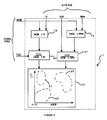
- Figure 2 is a block diagram of the interpretation functions performed on the drilling parameters generated from the apparatus of figure 1.
- FIG. 1 there is shown a drill string 10 suspended in a borehole 11 and having a typical drill bit 12 attached to its lower end.
- a sensor apparatus 13 for detection of downhole weight on bit (DWOB) and downhole torque (DT) constructed in accordance with the invention described in U.S. Patent 4,359,898 to Tanguy et al., which is incorporated herein by reference.
- the output of sensor 13 is fed to a transmitter assembly 15, for example, of the type shown and described in U.S. Patent 3,309,656, Godbey, which is also incorporated herein by reference.
- the transmitter 15 is located and attached within a special drill collar section 16 and functions to provide in the drilling fluid being circulated downwardly within the drill string 10, an acoustic signal that is modulated in accordance with the sensed data.
- the signal is detected at the surface by a receiving system 17 and processed by a processing means 14 to provide recordable data representative of the downhole measurements.
- a processing means 14 to provide recordable data representative of the downhole measurements.
- an acoustic data transmission system is mentioned herein, other types of telemetry systems, of course, may be employed, provided they are capable of transmitting an intelligible signal from downhole to the surface during the drilling operation.
- FIG. 2 illustrates the processing functions performed within the surface processing means 17.
- the downhole weight on bit (WOB) and downhole torque (TOR) signals derived from real time, in situ measurements made by MWD tool sensors 13 and delivered to the processor 17.
- processor 17 also provided to processor 17 are surface determined values of rotary speed (RPM), Bit Diameter (R), and Rate of Penetration (ROP).
- RPM rotary speed
- R Bit Diameter
- ROP Rate of Penetration
- processor 17 responds to the ROP and TOR inputs to detect the occurrence of one or two significant downhole events: the penetration of the drill bit into a highly porous formation such as would be present in a highly fractured bed, and the development of an undergauge bit
- processor 17 While it is possible for processor 17 to respond to ROP and TOR alone to produce desirable results, it has been found to be preferred to convert the ROP and TOR into the normalized quantities “Normalized ROP” (NROP) and “Dimensionless Torque” (T D ) respectively. This is done in processor 17 by forming the product of WOB and bit size (R) illustrated at block 18, forming the product of WOB and rotary speed (RPM) illustrated at block 19, and then dividing TOR (block 20) and ROP (block 21) respectively by these values to obtain T D and NROP.
- NROP Normalized ROP
- RPM rotary speed
- T D and NROP are combined in any suitable manner, such as by means of look up tables in processor 17, to generate an indication of high porosity or of an undergauge bit.
- This step is graphically illustrated in Figure 2 at block 22 which shows the NROP and T D data in the form of a crossplot.
- the crossplot of Figure 2 illustrates three regions of significance into which the NROP and T D data points might fall.
- Region 23 is that region determined by observation of the normal drilling process in which normal values of NROP and T D fall. Clearly the boundaries of region 23 may vary from well to well or from zone to zone in the same well where different lithologies are encountered.
- Data which falls outside of the "normal" region 23 indicate the occurrence of a possibly noteworthy drilling event.
- at least two such events include the occurrence of the penetration of the drill bit 12 into a highly porous zone such as a fractured zone and the development of an undergauge bit.
- zones of high porosity are characterized by both a relatively high value of NROP (relative to the normal values of region 23) and a relatively high value of T D .
- a second region 25 in the crossplot of figure 2 is illustrated as that region which is indicative of high porosity or of a fractured zone. Formation zones of high porosity are of great significance inasmuch as hydrocarbons are frequently found to be accumulated in such zones in certain geological regions such as the geologically complex region of offshore Southern California.
- Region 24 of the crossplot of figure 2 defines a third region of significant interest.
- relatively high values of T D accompanied by normal values of NROP correspond to the development of an undergauge or otherwise damaged bit. Timely detection of such an event enables the early removal of the bit from the hole for confirmation and replacement if the undergauge tendency or damage is verified.
Landscapes
- Engineering & Computer Science (AREA)
- Geology (AREA)
- Mining & Mineral Resources (AREA)
- Life Sciences & Earth Sciences (AREA)
- General Life Sciences & Earth Sciences (AREA)
- Fluid Mechanics (AREA)
- Environmental & Geological Engineering (AREA)
- Physics & Mathematics (AREA)
- Geochemistry & Mineralogy (AREA)
- Mechanical Engineering (AREA)
- Chemical & Material Sciences (AREA)
- Analytical Chemistry (AREA)
- Earth Drilling (AREA)
- Investigation Of Foundation Soil And Reinforcement Of Foundation Soil By Compacting Or Drainage (AREA)
- Geophysics And Detection Of Objects (AREA)
- Medicines That Contain Protein Lipid Enzymes And Other Medicines (AREA)
Description
- It is well known that oil field borehole evaluation may be performed by wireline conveyed instruments following the completion of the process of drilling a borehole. Such techniques have been available to the oil field industry for decades. Unfortunately, wireline investigation techniques are frequently disadvantageous due to their nature which requires that they be performed after drilling and after the pipe has been removed from the borehole. Due to their inability to make their investigations in real time, they are unable to assist in the selection of casing, coring and testing points without significant delay. Additionally, while the wireline techniques are effective in determining formation parameters, they are unable to provide insight into the borehole drilling process itself.
- In response to the shortcomings of wireline investigations, techniques which perform measurements while the borehole is being drilled are receiving greater acceptance by the oil field industry as standard, and indeed on occasion, indispensable services. Many such techniques differ from the traditional wireline techniques in that the MWD techniques are able to measure drilling parameters which not only provide information on the drilling process itself but also on the properties of the geological formations being drilled. Due to the relatively recent increased use of many MWD techniques, the oil field industry is still in the process of learning from experience how to most effectively utilize the new information that is becoming available from MWD. Perhaps not surprisingly, accumulating experience is revealing some rather unexpected results that may significantly improve the knowledge and efficiency of the process of forming boreholes in the earth.
- One recent example is described in U.S. patent 4,627,276 by Burgess and Lesso which is directed to a technique for remotely determining bit wear and for gaining insight into the efficiency of the drilling process from real time, in situ measurements of downhole weight on bit and downhole torque. Experience with this technique has shown that it is most effective the drilling of boreholes in deltaic sedimentary geologies having shale beds occasionally interrupted by sandstone formations with milled-tooth bits. Such a geology is found in the Gulf Coast region of the United States. Unfortunately, not all regions of the world have geologies as straight forward and as simple as the Gulf Coast. Take for example the highly complex geology of California in which the pacific plate is thrusting itself under the continental plate to produce complex, highly fractured formations. In these difficult geologies, it has been discovered that the techniques of the aforementioned patent are difficult if not impossible to apply. Another geological example in which one would not expect the techniques of U.S. Patent 4,627,276 to be effective is a volcanic geology. Thus, there is a need to discover and to develop methods of interpreting the measurements made while drilling complex geological formations that Will bring some insight into the nature of the formations being drilled and the drilling process itself.
- EP-A-0,163,426 discloses a method of assessing drilling conditions which includes determining torque (TOR), weight on bit (WOB), rate of penetration (ROP) and rotation speed (ROT) and computing values X = (TOR/WOB) and Y = (ROP/ROT) for simultaneous samples of TOR, WOB, ROP and ROT, X being a constant indicative of hole geometry. A history of points X and Y is built up and trends in the history monitored to determine drilling conditions. The trends can show rock type or bit wear depending on conditions.
- Such a clarifying technique has been discovered that reveals valuable and important information in the complex geologies of Califomia and, by extension, probably in the simpler sedimentary formations as well. Contrary to expectation, it has been discovered that the drilling parameters of Rate of Penetration (ROP) and Downhole Torque (DTOR) can be combined in a manner that not only may assist in identifying highly porous formations (highly fractured cherts in the California geology) but also may provide information on the undesirable drilling condition in which an undergauge or damaged bit is developed. The former is of major significance since in hard formations (such as chert) hydrocarbons tend to accumulate in fractures and the more highly fractured the formation, the greater the producibility of the stored hydrocarbons. The latter is also of major significance since the development of an undergauge bit means the diameter of the bit is slowly being reduced by abrasion of the formation on the bit to produce a slightly conical borehole which reduces in diameter with depth. As is wen known, a conical borehole is a situation to be avoided, if at all possible, since it seriously magnifies the difficulty of performing subsequent operations in that section of borehole, such as continuing the drilling process with a full gauge bit or setting casing. When a conical borehole has been developed, expensive remedial actions to remove the tapering tendency of the borehole must be undertaken, such as remaining the borehole, before further activities can be resumed.
- In the practice of the present invention, a parameter designated "dimensionless torque" is with a parameter designated "normalized rate of penetration" to yield the above described information. Dimensionless torque is determined by dividing a downhole measurement of torque by the product of downhole weight on bit and nominal bit size. Normalized Rate of Penetration is determined by dividing the surface acquired rate of penetration by the product of downhole weight on bit and surface acquired rotary speed. The concurrent values of dimensionless torque and normalized weight on bit are compared to normally expected values of those parameters. It has been discovered that if the values of both normalized Rate of Penetration and dimensionless torque are high compared to normally expected values, then a highly porous or fractured formation has been encountered by the drill bit. In this manner, the driller has an early indication of having encountered a possibly productive zone in the formation. It has also been discovered that if the value of Rate of Penetration is within the normal range while the value of dimensionless torque is abnormally high, then it is likely that the drill bit is being worn away to an undesirable undergauge condition and should be pulled and replaced with a full gauge bit. It is believed, in this situation, that the high torque is caused by the near-bit stabilizer abrading into the borehole walls.
- Figure 1 is an illustration of an MWD apparatus in a drill string having a drill bit while drilling a borehole.
- Figure 2 is a block diagram of the interpretation functions performed on the drilling parameters generated from the apparatus of figure 1.
- Referring initially to figure 1, there is shown a drill string 10 suspended in a
borehole 11 and having atypical drill bit 12 attached to its lower end. Immediately above thebit 12 is a sensor apparatus 13 for detection of downhole weight on bit (DWOB) and downhole torque (DT) constructed in accordance with the invention described in U.S. Patent 4,359,898 to Tanguy et al., which is incorporated herein by reference. The output of sensor 13 is fed to atransmitter assembly 15, for example, of the type shown and described in U.S. Patent 3,309,656, Godbey, which is also incorporated herein by reference. Thetransmitter 15 is located and attached within a specialdrill collar section 16 and functions to provide in the drilling fluid being circulated downwardly within the drill string 10, an acoustic signal that is modulated in accordance with the sensed data. The signal is detected at the surface by a receivingsystem 17 and processed by a processing means 14 to provide recordable data representative of the downhole measurements. Although an acoustic data transmission system is mentioned herein, other types of telemetry systems, of course, may be employed, provided they are capable of transmitting an intelligible signal from downhole to the surface during the drilling operation. - Reference is now made to Figure 2 for a detailed representation of a preferred embodiment of the present invention. Figure 2 illustrates the processing functions performed within the surface processing means 17. The downhole weight on bit (WOB) and downhole torque (TOR) signals derived from real time, in situ measurements made by MWD tool sensors 13 and delivered to the
processor 17. Also provided toprocessor 17 are surface determined values of rotary speed (RPM), Bit Diameter (R), and Rate of Penetration (ROP). In a broad sense,processor 17 responds to the ROP and TOR inputs to detect the occurrence of one or two significant downhole events: the penetration of the drill bit into a highly porous formation such as would be present in a highly fractured bed, and the development of an undergauge bit - While it is possible for
processor 17 to respond to ROP and TOR alone to produce desirable results, it has been found to be preferred to convert the ROP and TOR into the normalized quantities "Normalized ROP" (NROP) and "Dimensionless Torque" (TD) respectively. This is done inprocessor 17 by forming the product of WOB and bit size (R) illustrated at block 18, forming the product of WOB and rotary speed (RPM) illustrated at block 19, and then dividing TOR (block 20) and ROP (block 21) respectively by these values to obtain TD and NROP. - Once TD and NROP have been obtained, these values are combined in any suitable manner, such as by means of look up tables in
processor 17, to generate an indication of high porosity or of an undergauge bit. This step is graphically illustrated in Figure 2 atblock 22 which shows the NROP and TD data in the form of a crossplot. The crossplot of Figure 2 illustrates three regions of significance into which the NROP and TD data points might fall.Region 23 is that region determined by observation of the normal drilling process in which normal values of NROP and TD fall. Clearly the boundaries ofregion 23 may vary from well to well or from zone to zone in the same well where different lithologies are encountered. Thus, although not anticipated in a single bit run, it may be desirable to predetermine the boundaries of "normal"region 23 each time a new lithology is encountered. Indeed it may also be desirable to redetermine the boundaries ofregion 23 as changes occur in the drilling process such as the wear of thedrill bit 12 or the replacement of a worn bit with a new bit. - Data which falls outside of the "normal"
region 23 indicate the occurrence of a possibly noteworthy drilling event. As previously discussed, at least two such events include the occurrence of the penetration of thedrill bit 12 into a highly porous zone such as a fractured zone and the development of an undergauge bit. It has been discovered, much to the surprise of drilling experts, that zones of high porosity are characterized by both a relatively high value of NROP (relative to the normal values of region 23) and a relatively high value of TD. Thus, asecond region 25 in the crossplot of figure 2 is illustrated as that region which is indicative of high porosity or of a fractured zone. Formation zones of high porosity are of great significance inasmuch as hydrocarbons are frequently found to be accumulated in such zones in certain geological regions such as the geologically complex region of offshore Southern California. -
Region 24 of the crossplot of figure 2 defines a third region of significant interest. Here it has been discovered that relatively high values of TD accompanied by normal values of NROP correspond to the development of an undergauge or otherwise damaged bit. Timely detection of such an event enables the early removal of the bit from the hole for confirmation and replacement if the undergauge tendency or damage is verified.
Claims (5)
- A method of determining subsurface conditions encountered by a drill bit while drilling a borehole comprising measuring downhole torque TOR, downhole weight on bit WOB, rate of penetration ROP and rate of rotation RPM and combining the measurements to indicate said conditions, characterised in that die measurements are combined to determine dimensionless torque TD according to the relationship TD = TOR/(WOBxR) wherein R is the bit diameter, and normalised rate of penetration according to the relationship NROP = ROP/(WOBxRPM) and concurrent values of TD and NROP are compared with normally expected values of these parameters to generate an indication of high for-mation porosity or of a damaged or undergauge bit.
- A method as claimed in claim 1, wherein a signal indicative of WOB is generated and combined with a determination of R to generate a first product signal, the first product signal being combined with a signal indicative of TOR to generate a signal indicative of TD.
- A method as claimed in claim 1 or 2, wherein a signal indicative of WOB is generated and combined with a signal indicative of RPM to generate a second product signal, the second product signal being combined with a signal indicative of ROP to generate a signal indicative of NROP.
- A method as claimed in any preceding claim, wherein an indication of a high porosity formation is generated when the values of TD and NROP are higher than the normally expected values.
- A method as claimed in any of claims 1-3, wherein an indication of a damaged or undergauge bit is generated when the values of TD are higher than normally expected and the values of NROP are normal.
Applications Claiming Priority (2)
| Application Number | Priority Date | Filing Date | Title |
|---|---|---|---|
| US07/176,826 US4876886A (en) | 1988-04-04 | 1988-04-04 | Method for detecting drilling events from measurement while drilling sensors |
| US176826 | 1988-04-04 |
Publications (2)
| Publication Number | Publication Date |
|---|---|
| EP0336491A1 EP0336491A1 (en) | 1989-10-11 |
| EP0336491B1 true EP0336491B1 (en) | 1992-10-21 |
Family
ID=22646007
Family Applications (1)
| Application Number | Title | Priority Date | Filing Date |
|---|---|---|---|
| EP89200797A Expired EP0336491B1 (en) | 1988-04-04 | 1989-03-29 | Method for detecting drilling events from measurement while drilling sensors |
Country Status (5)
| Country | Link |
|---|---|
| US (1) | US4876886A (en) |
| EP (1) | EP0336491B1 (en) |
| CA (1) | CA1313862C (en) |
| DE (1) | DE68903242T2 (en) |
| NO (1) | NO891391L (en) |
Families Citing this family (49)
| Publication number | Priority date | Publication date | Assignee | Title |
|---|---|---|---|---|
| GB2221043B (en) * | 1988-07-20 | 1992-08-12 | Anadrill Int Sa | Method of determining the porosity of an underground formation being drilled |
| GB9015433D0 (en) * | 1990-07-13 | 1990-08-29 | Anadrill Int Sa | Method of determining the drilling conditions associated with the drilling of a formation with a drag bit |
| NO930044L (en) * | 1992-01-09 | 1993-07-12 | Baker Hughes Inc | PROCEDURE FOR EVALUATION OF FORMS AND DRILL CONDITIONS |
| GB9224003D0 (en) * | 1992-11-16 | 1993-01-06 | Minnesota Mining & Mfg | Magnetic recording materials |
| US6612382B2 (en) * | 1996-03-25 | 2003-09-02 | Halliburton Energy Services, Inc. | Iterative drilling simulation process for enhanced economic decision making |
| US7032689B2 (en) * | 1996-03-25 | 2006-04-25 | Halliburton Energy Services, Inc. | Method and system for predicting performance of a drilling system of a given formation |
| US5794720A (en) * | 1996-03-25 | 1998-08-18 | Dresser Industries, Inc. | Method of assaying downhole occurrences and conditions |
| GB9621871D0 (en) * | 1996-10-21 | 1996-12-11 | Anadrill Int Sa | Alarm system for wellbore site |
| US6155357A (en) * | 1997-09-23 | 2000-12-05 | Noble Drilling Services, Inc. | Method of and system for optimizing rate of penetration in drilling operations |
| US6026912A (en) | 1998-04-02 | 2000-02-22 | Noble Drilling Services, Inc. | Method of and system for optimizing rate of penetration in drilling operations |
| US6233498B1 (en) | 1998-03-05 | 2001-05-15 | Noble Drilling Services, Inc. | Method of and system for increasing drilling efficiency |
| US7029726B1 (en) | 1999-07-27 | 2006-04-18 | Quantum Corporation | Method for forming a servo pattern on a magnetic tape |
| GB2335785B (en) * | 1998-03-24 | 2002-09-18 | Quantum Corp | Multi-channel magnetic tape system having optical tracking servo |
| US7153366B1 (en) | 1998-03-24 | 2006-12-26 | Quantum Corporation | Systems and method for forming a servo pattern on a magnetic tape |
| WO2000009857A1 (en) * | 1998-08-17 | 2000-02-24 | Sasol Mining (Proprietary) Limited | Method and apparatus for exploration drilling |
| US6152246A (en) * | 1998-12-02 | 2000-11-28 | Noble Drilling Services, Inc. | Method of and system for monitoring drilling parameters |
| JP4293733B2 (en) | 1999-02-16 | 2009-07-08 | クウォンタム・コーポレイション | Servo signal writing method to magnetic tape |
| EP1205913A4 (en) | 1999-02-17 | 2002-08-14 | Quantum Corp | Method of writing servo signal on magnetic tape |
| FR2792363B1 (en) * | 1999-04-19 | 2001-06-01 | Inst Francais Du Petrole | METHOD AND SYSTEM FOR DETECTING THE LONGITUDINAL MOVEMENT OF A DRILLING TOOL |
| US6961200B2 (en) * | 1999-07-27 | 2005-11-01 | Quantum Corporation | Optical servo track identification on tape storage media |
| US6558774B1 (en) | 1999-08-17 | 2003-05-06 | Quantum Corporation | Multiple-layer backcoating for magnetic tape |
| US6382331B1 (en) | 2000-04-17 | 2002-05-07 | Noble Drilling Services, Inc. | Method of and system for optimizing rate of penetration based upon control variable correlation |
| US6940676B1 (en) | 2000-06-07 | 2005-09-06 | Quantum Corporation | Triple push-pull optical tracking system |
| RU2190095C2 (en) * | 2000-07-19 | 2002-09-27 | Дочернее общество с ограниченной ответственностью Буровая компания ОАО "Газпром" | Procedure determining wear-out degree of rock disintegration tool in process of drilling |
| US6634441B2 (en) | 2000-08-21 | 2003-10-21 | Halliburton Energy Services, Inc. | System and method for detecting roller bit bearing wear through cessation of roller element rotation |
| US6631772B2 (en) | 2000-08-21 | 2003-10-14 | Halliburton Energy Services, Inc. | Roller bit rearing wear detection system and method |
| US6722450B2 (en) | 2000-11-07 | 2004-04-20 | Halliburton Energy Svcs. Inc. | Adaptive filter prediction method and system for detecting drill bit failure and signaling surface operator |
| US6712160B1 (en) | 2000-11-07 | 2004-03-30 | Halliburton Energy Services Inc. | Leadless sub assembly for downhole detection system |
| US7357197B2 (en) | 2000-11-07 | 2008-04-15 | Halliburton Energy Services, Inc. | Method and apparatus for monitoring the condition of a downhole drill bit, and communicating the condition to the surface |
| US6648082B2 (en) | 2000-11-07 | 2003-11-18 | Halliburton Energy Services, Inc. | Differential sensor measurement method and apparatus to detect a drill bit failure and signal surface operator |
| US6817425B2 (en) | 2000-11-07 | 2004-11-16 | Halliburton Energy Serv Inc | Mean strain ratio analysis method and system for detecting drill bit failure and signaling surface operator |
| RU2182659C1 (en) * | 2001-03-19 | 2002-05-20 | Общество с ограниченной ответственностью "ЮганскНИПИнефть" | Method of determination of rock-cutting tool serviceability |
| RU2188939C1 (en) * | 2001-05-25 | 2002-09-10 | Общество с ограниченной ответственностью "ЮганскНИПИнефть" | Method of determining rock-cutting tool serviceability |
| US6940681B2 (en) | 2001-08-20 | 2005-09-06 | Quantum Corporation | Optical to magnetic alignment in magnetic tape system |
| US7023650B2 (en) | 2001-11-07 | 2006-04-04 | Quantum Corporation | Optical sensor to recording head alignment |
| EA009115B1 (en) * | 2002-04-19 | 2007-10-26 | Марк У. Хатчинсон | A method for determining a drilling malfunction |
| US6892812B2 (en) | 2002-05-21 | 2005-05-17 | Noble Drilling Services Inc. | Automated method and system for determining the state of well operations and performing process evaluation |
| US6820702B2 (en) | 2002-08-27 | 2004-11-23 | Noble Drilling Services Inc. | Automated method and system for recognizing well control events |
| US6802378B2 (en) | 2002-12-19 | 2004-10-12 | Noble Engineering And Development, Ltd. | Method of and apparatus for directional drilling |
| US6980390B2 (en) | 2003-02-05 | 2005-12-27 | Quantum Corporation | Magnetic media with embedded optical servo tracks |
| US7187515B2 (en) | 2003-02-05 | 2007-03-06 | Quantum Corporation | Method and system for tracking magnetic media with embedded optical servo tracks |
| GB2413403B (en) | 2004-04-19 | 2008-01-09 | Halliburton Energy Serv Inc | Field synthesis system and method for optimizing drilling operations |
| WO2009075667A2 (en) * | 2007-11-30 | 2009-06-18 | Halliburton Energy Services | Method and system for predicting performance of a drilling system having multiple cutting structures |
| US8042623B2 (en) | 2008-03-17 | 2011-10-25 | Baker Hughes Incorporated | Distributed sensors-controller for active vibration damping from surface |
| AU2009300240B2 (en) * | 2008-10-03 | 2013-02-21 | Halliburton Energy Services, Inc. | Method and system for predicting performance of a drilling system |
| DE102008052510B3 (en) * | 2008-10-21 | 2010-07-22 | Tracto-Technik Gmbh & Co. Kg | A method of determining the wear of a load-bearing linkage of an earthworking device |
| US8881414B2 (en) | 2009-08-17 | 2014-11-11 | Magnum Drilling Services, Inc. | Inclination measurement devices and methods of use |
| US8528219B2 (en) | 2009-08-17 | 2013-09-10 | Magnum Drilling Services, Inc. | Inclination measurement devices and methods of use |
| US10689910B2 (en) * | 2016-06-30 | 2020-06-23 | Schlumberger Technology Corporation | Bi-directional drilling systems and methods |
Family Cites Families (18)
| Publication number | Priority date | Publication date | Assignee | Title |
|---|---|---|---|---|
| USRE21297E (en) | 1939-12-12 | Depth recorder for a well dkul | ||
| US21297A (en) * | 1858-08-24 | Selves and jos | ||
| US2372576A (en) * | 1942-04-20 | 1945-03-27 | John T Hayward | Method of determining formation porosity during drilling |
| US2669871A (en) * | 1949-03-29 | 1954-02-23 | Lubinski Arthur | Wear of bit indicator |
| US3368400A (en) * | 1964-07-14 | 1968-02-13 | Shell Oil Co | Method for determining the top of abnormal formation pressures |
| US3541852A (en) * | 1968-11-29 | 1970-11-24 | Dresser Ind | Electronic system for monitoring drilling conditions relating to oil and gas wells |
| US3581564A (en) * | 1969-05-14 | 1971-06-01 | Exxon Production Research Co | Method for detecting roller bit bearing failure |
| US3898880A (en) * | 1971-06-25 | 1975-08-12 | Cities Service Oil Co | Electronic supervisory monitoring method for drilling wells |
| US3774445A (en) * | 1971-11-24 | 1973-11-27 | Texaco Inc | Method and apparatus for monitoring the wear on a rotary drill bit |
| US3782190A (en) * | 1972-08-03 | 1974-01-01 | Texaco Inc | Method and apparatus for rotary drill testing |
| US3916684A (en) * | 1972-10-10 | 1975-11-04 | Texaco Inc | Method and apparatus for developing a surface well-drilling log |
| GB1439519A (en) * | 1973-11-02 | 1976-06-16 | Texaco Development Corp | Method and apapratus for rotary drilling |
| US4064749A (en) * | 1976-11-11 | 1977-12-27 | Texaco Inc. | Method and system for determining formation porosity |
| FR2485616B1 (en) * | 1980-06-27 | 1986-02-28 | Pk I | SYSTEM FOR AUTOMATICALLY CONTROLLING A ROTATION SOIL DRILLING APPARATUS |
| US4359898A (en) * | 1980-12-09 | 1982-11-23 | Schlumberger Technology Corporation | Weight-on-bit and torque measuring apparatus |
| US4655300A (en) * | 1984-02-21 | 1987-04-07 | Exxon Production Research Co. | Method and apparatus for detecting wear of a rotatable bit |
| GB8411361D0 (en) * | 1984-05-03 | 1984-06-06 | Schlumberger Cambridge Researc | Assessment of drilling conditions |
| US4627276A (en) * | 1984-12-27 | 1986-12-09 | Schlumberger Technology Corporation | Method for measuring bit wear during drilling |
-
1988
- 1988-04-04 US US07/176,826 patent/US4876886A/en not_active Expired - Fee Related
-
1989
- 1989-03-29 DE DE8989200797T patent/DE68903242T2/en not_active Expired - Fee Related
- 1989-03-29 EP EP89200797A patent/EP0336491B1/en not_active Expired
- 1989-04-03 NO NO89891391A patent/NO891391L/en unknown
- 1989-04-03 CA CA000595540A patent/CA1313862C/en not_active Expired - Fee Related
Also Published As
| Publication number | Publication date |
|---|---|
| DE68903242T2 (en) | 1993-03-25 |
| CA1313862C (en) | 1993-02-23 |
| NO891391L (en) | 1989-10-05 |
| EP0336491A1 (en) | 1989-10-11 |
| US4876886A (en) | 1989-10-31 |
| NO891391D0 (en) | 1989-04-03 |
| DE68903242D1 (en) | 1992-11-26 |
Similar Documents
| Publication | Publication Date | Title |
|---|---|---|
| US4876886A (en) | Method for detecting drilling events from measurement while drilling sensors | |
| EP0350978B1 (en) | Method for determining drilling conditions while drilling | |
| EP0339752B1 (en) | Pore pressure formation evaluation while drilling | |
| US4949575A (en) | Formation volumetric evaluation while drilling | |
| US6386297B1 (en) | Method and apparatus for determining potential abrasivity in a wellbore | |
| CA2519822C (en) | Apparatus and method of identifying rock properties while drilling | |
| US10697294B2 (en) | Vibration while drilling data processing methods | |
| US6480118B1 (en) | Method of drilling in response to looking ahead of drill bit | |
| US4914591A (en) | Method of determining rock compressive strength | |
| US7650241B2 (en) | Use of the dynamic downhole measurements as lithology indicators | |
| US5415030A (en) | Method for evaluating formations and bit conditions | |
| CN115943302B (en) | Surface logging using rock cuttings-based rock physics analysis | |
| AU2002301925B2 (en) | Method for Determining Wellbore Diameter by Processing Multiple Sensor Measurements | |
| US6227044B1 (en) | Methods and apparatus for detecting torsional vibration in a bottomhole assembly | |
| AU2023214234A1 (en) | Vibration while drilling data processing methods | |
| WO2014014727A2 (en) | Determination of subsurface properties of a well | |
| US4981036A (en) | Method of determining the porosity of an underground formation being drilled | |
| US5010765A (en) | Method of monitoring core sampling during borehole drilling | |
| US5758539A (en) | Logging method and system for measuring mechanical parameters of the formations crossed through by a borehole | |
| Reckmann et al. | Using dynamics measurements while drilling to detect lithology changes and to model drilling dynamics | |
| US4924950A (en) | Method of drilling a well by utilizing AE/MA measurement | |
| WO2025188818A1 (en) | At-bit mechanical formation property measurements |
Legal Events
| Date | Code | Title | Description |
|---|---|---|---|
| PUAI | Public reference made under article 153(3) epc to a published international application that has entered the european phase |
Free format text: ORIGINAL CODE: 0009012 |
|
| AK | Designated contracting states |
Kind code of ref document: A1 Designated state(s): DE FR GB IT NL |
|
| 17P | Request for examination filed |
Effective date: 19900320 |
|
| 17Q | First examination report despatched |
Effective date: 19910416 |
|
| GRAA | (expected) grant |
Free format text: ORIGINAL CODE: 0009210 |
|
| ITF | It: translation for a ep patent filed | ||
| AK | Designated contracting states |
Kind code of ref document: B1 Designated state(s): DE FR GB IT NL |
|
| ET | Fr: translation filed | ||
| REF | Corresponds to: |
Ref document number: 68903242 Country of ref document: DE Date of ref document: 19921126 |
|
| PG25 | Lapsed in a contracting state [announced via postgrant information from national office to epo] |
Ref country code: GB Effective date: 19930329 |
|
| PGFP | Annual fee paid to national office [announced via postgrant information from national office to epo] |
Ref country code: DE Payment date: 19930518 Year of fee payment: 5 |
|
| PLBE | No opposition filed within time limit |
Free format text: ORIGINAL CODE: 0009261 |
|
| STAA | Information on the status of an ep patent application or granted ep patent |
Free format text: STATUS: NO OPPOSITION FILED WITHIN TIME LIMIT |
|
| PG25 | Lapsed in a contracting state [announced via postgrant information from national office to epo] |
Ref country code: NL Effective date: 19931001 |
|
| 26N | No opposition filed | ||
| NLV4 | Nl: lapsed or anulled due to non-payment of the annual fee | ||
| GBPC | Gb: european patent ceased through non-payment of renewal fee |
Effective date: 19930329 |
|
| PG25 | Lapsed in a contracting state [announced via postgrant information from national office to epo] |
Ref country code: FR Effective date: 19931130 |
|
| REG | Reference to a national code |
Ref country code: FR Ref legal event code: ST |
|
| PG25 | Lapsed in a contracting state [announced via postgrant information from national office to epo] |
Ref country code: DE Effective date: 19941201 |
|
| PG25 | Lapsed in a contracting state [announced via postgrant information from national office to epo] |
Ref country code: IT Free format text: LAPSE BECAUSE OF NON-PAYMENT OF DUE FEES;WARNING: LAPSES OF ITALIAN PATENTS WITH EFFECTIVE DATE BEFORE 2007 MAY HAVE OCCURRED AT ANY TIME BEFORE 2007. THE CORRECT EFFECTIVE DATE MAY BE DIFFERENT FROM THE ONE RECORDED. Effective date: 20050329 |