EP0336220A1 - Water circulation for a lithotripter - Google Patents
Water circulation for a lithotripter Download PDFInfo
- Publication number
- EP0336220A1 EP0336220A1 EP89105144A EP89105144A EP0336220A1 EP 0336220 A1 EP0336220 A1 EP 0336220A1 EP 89105144 A EP89105144 A EP 89105144A EP 89105144 A EP89105144 A EP 89105144A EP 0336220 A1 EP0336220 A1 EP 0336220A1
- Authority
- EP
- European Patent Office
- Prior art keywords
- water
- pressure
- valve
- cushion
- water cushion
- Prior art date
- Legal status (The legal status is an assumption and is not a legal conclusion. Google has not performed a legal analysis and makes no representation as to the accuracy of the status listed.)
- Granted
Links
Images
Classifications
-
- A—HUMAN NECESSITIES
- A61—MEDICAL OR VETERINARY SCIENCE; HYGIENE
- A61B—DIAGNOSIS; SURGERY; IDENTIFICATION
- A61B17/00—Surgical instruments, devices or methods, e.g. tourniquets
- A61B17/22—Implements for squeezing-off ulcers or the like on the inside of inner organs of the body; Implements for scraping-out cavities of body organs, e.g. bones; Calculus removers; Calculus smashing apparatus; Apparatus for removing obstructions in blood vessels, not otherwise provided for
- A61B17/225—Implements for squeezing-off ulcers or the like on the inside of inner organs of the body; Implements for scraping-out cavities of body organs, e.g. bones; Calculus removers; Calculus smashing apparatus; Apparatus for removing obstructions in blood vessels, not otherwise provided for for extracorporeal shock wave lithotripsy [ESWL], e.g. by using ultrasonic waves
- A61B17/2251—Implements for squeezing-off ulcers or the like on the inside of inner organs of the body; Implements for scraping-out cavities of body organs, e.g. bones; Calculus removers; Calculus smashing apparatus; Apparatus for removing obstructions in blood vessels, not otherwise provided for for extracorporeal shock wave lithotripsy [ESWL], e.g. by using ultrasonic waves characterised by coupling elements between the apparatus, e.g. shock wave apparatus or locating means, and the patient, e.g. details of bags, pressure control of bag on patient
-
- A—HUMAN NECESSITIES
- A61—MEDICAL OR VETERINARY SCIENCE; HYGIENE
- A61B—DIAGNOSIS; SURGERY; IDENTIFICATION
- A61B90/00—Instruments, implements or accessories specially adapted for surgery or diagnosis and not covered by any of the groups A61B1/00 - A61B50/00, e.g. for luxation treatment or for protecting wound edges
- A61B90/06—Measuring instruments not otherwise provided for
- A61B2090/064—Measuring instruments not otherwise provided for for measuring force, pressure or mechanical tension
Definitions
- the invention relates to the water cycle of a device for shock wave treatment, in particular a lithotripter.
- a lithotripter is known in which the shock wave application is carried out with a water cushion, via which the shock wave is coupled into the patient's body.
- degassed and softened water is used as a coupling medium in the water cushion, which is tempered to 37 ° C.
- a coupling gel is applied between the water cushion and the patient's body, as is done in a known manner in ultrasound diagnostics. A certain coupling pressure of the water cushion is required for the bubble-free coupling of the two interfaces water / patient body and to compensate for unevenness of the patient body.
- the object of the invention is therefore to propose a water cycle that meets the following requirements: - Coupling the water cushion to the patient's body in any position between the shock wave source and the second focus - Adaptation to the various diverent patients - Bubble-free coupling of the water cushion to the patient's body in the area affected by the shock wave - Setting a preselected coupling pressure of the water cushion to the patient's body - Keeping the coupling pressure constant in the working area of the therapy unit (different working levels and coupling directions: from above, from below and from the side) - Fast pressure equalization with simultaneous high filling and emptying speed of the water cushion with minimal overshoot of the level within certain limits.
- the function of the water circuit according to the invention is based on the interaction of a rinsing and a main circuit. Both circuits are advantageous with one pump operated together. In the event of fluctuations in the liquid flows, the pressure potentials are kept constant with pressure control valves. All functions of the water cycle can be checked by suitable monitoring devices.
- the invention can be applied to different types of water cushions: both different sizes or types can be operated with the water cycle according to the invention.
- water cushions with flexible bellows and foil ends or water cushions made of stretched foils can be operated, such as silicone foils that have a balloon-shaped expansion in the coupling area.
- the parallel main and rinsing circuits specified in subclaims 2 and 3 allow the water cushion to be quickly started up and down on the patient's body for the coupling and uncoupling process, since a high filling and emptying speed is possible.
- the invention enables rapid pressure equalization and small overshoot ranges of the level in the water cushion. Since only limited overpressures can arise in the water cushion due to the parallel system structure in the event of malfunctions, a high level of patient safety is guaranteed against overpressures in the event of malfunctions.
- the correct coupling pressure is automatically set at every level and in every position of the water cushion (coupling of the water cushion to the patient's body from above, from below and from the side possible).
- the pressure sensor is designed as a differential pressure sensor and allows the compensation of atmospheric air pressure fluctuations and a very precise adjustment of the coupling pressure in the water cushion to the patient's body (the pressure of the coupling medium in the water cushion can be precisely regulated in the millibar range).
- the version with an open expansion tank allows easy filling of the system and easy ventilation of the water cushion.
- the water circuit according to the invention can be expanded by a degassing system which can then be connected in parallel to the water circuit described.
- the gases and gases dissolved in the coupling medium, which are generated by cavitation on the spark gap, for example, can be easily removed from the overall system.
- flow monitors can be used as simple but safe monitoring devices for the functioning of the circuit.
- the invention is illustrated by a figure.
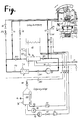
- the figure shows at the top right a lithotripter with the bed L, the patient's body PK and the therapy head TK guided on a rail, which has a shock wave source and - arranged here below - a water cushion WK for coupling the shock waves into the patient's body PK.
- the water cycle according to the invention essentially consists of the four components: - main circuit - rinsing cycle - pressure control and - degassing plant, which are described in more detail below.
- the flushing and pressure control system is operated with the circulation pump P1. With this pump, the water is continuously circulated in the main circuit and heated to 37 ° C with the H heater.
- the main circuit flow path is as follows: - pump P1 - Flow switch SW1 - H heating, with temperature sensors T1 for overtemperature and T2 for temperature control - DR2 pressure control valve - Expansion tank AB - Pressure maintenance valve DR1 - pump P1.
- the pressure holding valves DR1 and DR2 generate defined pressure potentials for the pressure control on the suction and pressure side of the circulation pump P1, which are almost independent of flow fluctuations.
- the characteristic curves of these pressure-maintaining valves run in such a way that flow fluctuations in the medium flowing through result in only a slight pressure fluctuation. These flow fluctuations occur when the filling or emptying of the water cushion WK (see pressure control below) is triggered in the main circuit by switching the valves V3 or V4, which are available for pressure control.
- the expansion tank AB In the expansion tank AB, the liquid volume fluctuations in the overall circuit are compensated for, which result from the pressure control of the water cushion WK and from the coupling and uncoupling of the water cushion WK to the patient's body.
- the expansion tank AB also serves to automatically vent the system.
- the pressure in the water cushion WK is detected by an electronic pressure sensor PR and its output signal is sent to the pressure regulator, for example a three-point step regulator, via evaluation electronics.
- the pressure sensor PR is preferably installed at the level of the coupling surface of the water cushion WK and is connected to the inner part of the water cushion WK with a short connecting line.
- the position of the pressure sensor PR with respect to the axes of rotation of the therapy head TK is selected such that an average water pressure in the immediate vicinity of almost the entire working area of the therapy head TK the coupling surface of the water cushion WK is measured. With this procedure, the coupling pressure of the water cushion WK to the patient's body PK can be precisely measured and thus also precisely controlled.
- the pressure measuring cell of the pressure sensor PR is preferably designed as a differential pressure sensor, that is to say the pressure difference between the pressure in the water cushion WK and the ambient pressure (atmospheric air pressure) is measured. This compensates for atmospheric fluctuations in air pressure.
- the pressure regulator controls valve V3 or V4 with a frequency that depends on the control deviation.
- the water cushion WK is filled with the valve V4 and emptied with the valve V3, the pressure in the water cushion WK increasing or decreasing analogously to this. If there is no control deviation, both valves V3 and V4 are closed.
- the water cushion is vented with the flushing circuit, dirt particles are filtered out by the shock wave source and heated and degassed water is led to the water cushion WK.
- the rinsing circuit is connected in parallel to the main circuit.
- the flow path leads from the main circuit via the pressure holding valve DR3 and the shutoff valve flushing V6 to the water cushion WK and the filter F1 and the drain Blocking valve rinsing circuit V2 back to the main circuit.
- the pressure maintenance valve DR3 in connection with the pressure maintenance valves DR1 and DR2 of the main circuit generates almost constant pressure ratios for the rinsing circuit, so that the flow in the rinsing circuit or in the main circuit cannot stop when the pressure control is operated.
- the inflow and outflow of the flushing circuit with respect to the water cushion WK is also adjusted so that the flushing circuit is in balance and there is no constant filling or emptying of the water cushion WK.
- the flow balance in the rinsing circuit is adjusted using a flow control system for control reasons.
- the valve V6 is then replaced by a proportional valve.
- the degassing system essentially consists of the degassing tank EB and the lines provided with pumps P2, P3, valves V5, RV and filters F2, F3, which can be connected to the rest of the system via coupling connections K1, K2, K3, K4.
- the degassing plant essentially has two operating phases: 1st filling phase 2nd degassing phase.
- the water is drawn off the rinsing circuit via filter F1.
- Air present in filter F1 which accumulates in it after the system has been refilled or after changing electrodes, is removed from the degassing system during the filling phase.
- the degassing pump P2 is switched off, the filling pump P3 is switched on and valve V5 opened.
- the degassing tank EB is filled with the filling pump P3 via the sieve filter F3 and the valve V5.
- the check valve RV opens and the degassing tank EB is vented via the expansion tank AB. With the flow monitor SW2, the complete filling of the degassing container EB is detected and switched to the degassing mode with an adjustable time delay.
- Valve V5 and check valve RV are closed during the degassing phase.
- the flow path leads from the expansion tank AB via the screen filter F2 and the fixed throttle FD to the degassing tank EB.
- the degassing pump P2 With the degassing pump P2, the water is pumped out and the throttling action from the fixed throttle FD (Venturi tube) generates a further pressure reduction, which causes the degassing of the water by shifting the solution equilibrium.
- the degassing pump P2 is flanged directly to the housing of the degassing tank EB.
- the flow path leads from pump P2 back to expansion tank AB.
- the negative pressure in the degassing tank EB is, for example, approximately -0.85 bar compared to the atmospheric air pressure.
- the water / air mixture present here separates due to the rising air bubbles.
- the rising air bubbles in turn act as degassing nuclei, which intensify the degassing process.
- a rough surface of the degassing container EB additionally reinforces the process according to the same principle.
Abstract
Description
Die Erfindung betrifft den Wasserkreislauf eines Geräts zur Stosswellenbehandlung, insbesondere eines Lithotripters.The invention relates to the water cycle of a device for shock wave treatment, in particular a lithotripter.
Aus dem Prospekt: Vom Ende der Steinzeit, HV 5000 08/87 der DORNIER MEDIZINTECHNIK GMBH, 8034 Germering, ist ein Lithotripter bekannt, bei dem die Stosswellenapplikation mit einem Wasserkissen erfolgt, über das die Stosswelle in den Patientenkörper eingekoppelt wird. Für die verlustlose Erzeugung und Einkoppelung der Stosswelle wird im Wasserkissen als Koppelmedium entgastes und enthärtetes Wasser benutzt, das auf 37°C temperiert wird. Zwischen das Wasserkissen und den Patientenkörper wird ein Koppelgel appliziert, wie dies in bekannter Weise in der Ultraschall-Diagnostik durchgeführt wird. Zur blasenfreien Ankoppelung der beiden Grenzflächen Wasser/Patientenkörper und zum Ausgleich von Unebenheiten des Patientenkörpers, ist ein bestimmter Ankoppelungsdruck des Wasserkissens erforderlich. Für diese Niveau-Einstellung des Wasserkissens (Anpassung an verschieden korpulente Patienten) und die Konstanthaltung des Ankoppelungsdrucks wird eine Druckregelung für den Druck des Koppelmediums innerhalb des Wasserkissens benötigt. Durch den hohen Freiheitsgrad der Therapieeinheit - so ist ein Verschwenken über, seitlich und unter den Patienten körper möglich - werden aufgrund der durch die vertikalen Lageänderungen bedingten Druckschwankungen (hydrostatische Druckänderungen) im Wasserkissen besondere Anforderungen an die Druckregelung gestellt.From the brochure: From the end of the Stone Age, HV 5000 08/87 from DORNIER MEDIZINTECHNIK GMBH, 8034 Germering, a lithotripter is known in which the shock wave application is carried out with a water cushion, via which the shock wave is coupled into the patient's body. For the lossless generation and coupling of the shock wave, degassed and softened water is used as a coupling medium in the water cushion, which is tempered to 37 ° C. A coupling gel is applied between the water cushion and the patient's body, as is done in a known manner in ultrasound diagnostics. A certain coupling pressure of the water cushion is required for the bubble-free coupling of the two interfaces water / patient body and to compensate for unevenness of the patient body. For this level adjustment of the water cushion (adaptation to differently corpulent patients) and keeping the coupling pressure constant, a pressure control for the pressure of the coupling medium within the water cushion is required. Due to the high degree of freedom of the therapy unit - this is pivoting above, to the side and below the patient body possible - due to the pressure fluctuations caused by the vertical changes in position (hydrostatic pressure changes) in the water cushion, special demands are placed on the pressure control.
Aufgabe der Erfindung ist es daher einen Wasserkreislauf vorzuschlagen, der folgende Anforderungen erfüllt:
- Ankoppelung des Wasserkissens an den Patientenkörper in jeder beliebigen Lage zwischen der Stosswellenquelle und dem zweiten Fokus
- Anpassung an die verschieden korpulenten Patienten
- Blasenfreie Ankoppelung des Wasserkissens an den Patientenkörper im Einwirkungsbereich der Stosswelle
- Einstellung eines vorgewählten Ankoppelungsdrucks des Wasserkissens an den Patientenkörper
- Konstanthaltung des Ankoppelungsdrucks im Arbeitsbereich der Therapieeinheit (verschiedene Arbeitsniveaus und Ankoppelrichtungen: von oben, von unten und von der Seite)
- Schneller Druckausgleich bei gleichzeitig grosser Befüll- und Entleerungsgeschwindigkeit des Wasserkissens bei möglichst geringem Überschwingen des Niveaus in bestimmten Grenzen.The object of the invention is therefore to propose a water cycle that meets the following requirements:
- Coupling the water cushion to the patient's body in any position between the shock wave source and the second focus
- Adaptation to the various corpulent patients
- Bubble-free coupling of the water cushion to the patient's body in the area affected by the shock wave
- Setting a preselected coupling pressure of the water cushion to the patient's body
- Keeping the coupling pressure constant in the working area of the therapy unit (different working levels and coupling directions: from above, from below and from the side)
- Fast pressure equalization with simultaneous high filling and emptying speed of the water cushion with minimal overshoot of the level within certain limits.
Diese Aufgabe wird erfindungsgemäss gelöst von einem Wasserkreislauf mit den Merkmalen des Hauptanspruchs. Ausführungen der Erfindung sind Gegenstände von Unteransprüchen.This object is achieved according to the invention by a water cycle with the features of the main claim. Embodiments of the invention are the subject of subclaims.
Die Funktion des erfindungsgemässen Wasserkreislaufs beruht auf dem Zusammenwirken eines Spül- und eines Hauptkreislaufs. Beide Kreisläufe werden vorteilhaft mit einer Pumpe gemeinsam betrieben. Bei Schwankungen der der Flüssigkeitsströme werden die Druckpotentiale mit Druckhalteventilen konstant gehalten. Sämtliche Funktionen des Wasserkreislaufs können durch geeignete Überwachungseinrichtungen kontrolliert werden.The function of the water circuit according to the invention is based on the interaction of a rinsing and a main circuit. Both circuits are advantageous with one pump operated together. In the event of fluctuations in the liquid flows, the pressure potentials are kept constant with pressure control valves. All functions of the water cycle can be checked by suitable monitoring devices.
Die Erfindung lässt sich bei verschiedenen Wasserkissen-Typen anwenden: sowohl verschiedene Grössen oder Bauarten können mit dem erfindungsgemässen Wasserkreislauf bedient wird. So können Wasserkissen mit flexiblem Faltenbalg und Folienabschluss oder Wasserkissen aus gespannten Folien bedient werden, wie zum Beispiel Silikonfolien, die im Ankoppelbereich eine ballonförmige Ausweitung haben. Die in den Unteransprüchen 2 und 3 angegebenen, parallelen Haupt- und Spülkreisläufe erlauben ein schnelles Anfahren und Abfahren des Wasserkissens an den Patientenkörper für den Ankoppelungs- und Abkoppelungsvorgang, da eine hohe Befüll- und Entleerungsgeschwindigkeit möglich ist. Die Erfindung ermöglicht einen schnellen Druckausgleich und geringe Überschwingweiten des Niveaus im Wasserkissen. Da aufgrund des parallelen Systemaufbaus bei Störungen nur begrenzte Überdrücke im Wasserkissen entstehen können, ist eine hohe Patientensicherheit gegenüber Überdrücken bei Störungen gewährleistet.The invention can be applied to different types of water cushions: both different sizes or types can be operated with the water cycle according to the invention. For example, water cushions with flexible bellows and foil ends or water cushions made of stretched foils can be operated, such as silicone foils that have a balloon-shaped expansion in the coupling area. The parallel main and rinsing circuits specified in
In der Ausführung, bei der ein Drucksensor in unmittelbarer Nähe der Ankoppelfläche des Wasserkissens angeordnet ist, stellt sich automatisch der richtige Ankoppeldruck auf jedem Niveau und in jeder Lage des Wasserksisens ein (Ankoppelung des Wasserkissens an den Patientenkörper von oben, von unten und von der Seite möglich). Diese Ausführung erlaubt eine individuelle, sensible Einstellbarkeit des Ankoppelungsdruckes.In the version in which a pressure sensor is arranged in the immediate vicinity of the coupling surface of the water cushion, the correct coupling pressure is automatically set at every level and in every position of the water cushion (coupling of the water cushion to the patient's body from above, from below and from the side possible). This version allows an individual, sensitive adjustability of the coupling pressure.
In einer bevorzugten Ausführung wird der Drucksensor als Differenzdruckaufnehmer ausgebildet und erlaubt die Kompensation von atmosphärischen Luftdruckschwankungen und eine sehr genaue Einstellung des Ankoppelungsdrucks im Wasserkissen an dem Patientenkörper (der Druck des Koppelmediums im Wasserkissen ist im Millibarbereich genau regelbar).In a preferred embodiment, the pressure sensor is designed as a differential pressure sensor and allows the compensation of atmospheric air pressure fluctuations and a very precise adjustment of the coupling pressure in the water cushion to the patient's body (the pressure of the coupling medium in the water cushion can be precisely regulated in the millibar range).
Die Ausführung mit offenem Ausgleichsbehälter erlaubt eine einfache Befüllung der Anlage und eine problemlose Entlüftung des Wasserkissens.The version with an open expansion tank allows easy filling of the system and easy ventilation of the water cushion.
Der erfindungsgemässe Wasserkreislauf kann um eine Entgasungsanlage erweitert werden, die dann dem beschriebenen Wasserkreislauf parallel geschaltet werden kann. Damit können die im Koppelmedium gelösten Gase und Gase, die zum Beispiel an der Funkenstrecke durch Kavitation entstehen, leicht aus dem Gesamtsystem entfernt werden.The water circuit according to the invention can be expanded by a degassing system which can then be connected in parallel to the water circuit described. The gases and gases dissolved in the coupling medium, which are generated by cavitation on the spark gap, for example, can be easily removed from the overall system.
In einer weiteren Ausführung können Strömungswächter als einfache, aber sichere Überwachungsgeräte für die Funktion des Kreislaufes eingesetzt werden.In a further embodiment, flow monitors can be used as simple but safe monitoring devices for the functioning of the circuit.
Die Erfindung wird anhand einer Figur näher erläutert.The invention is illustrated by a figure.
Die Figur zeigt rechts oben eine Lithotripter mit der Liege L, dem Patientenkörper PK und dem an einer Schiene geführten Therapiekopf TK, der eine Stosswellenquelle und - hier darunter angeordnet - ein Wasserkissen WK zum Einkoppeln der Stosswellen in den Patientenkörper PK besitzt.
Der erfindungsgemässe Wasserkreislauf besteht im wesentlichen aus den vier Komponenten:
- Hauptkreislauf
- Spülkreislauf
- Druckregelung und
- Entgasungsanlage,
die nachfolgend näher beschrieben sind.The figure shows at the top right a lithotripter with the bed L, the patient's body PK and the therapy head TK guided on a rail, which has a shock wave source and - arranged here below - a water cushion WK for coupling the shock waves into the patient's body PK.
The water cycle according to the invention essentially consists of the four components:
- main circuit
- rinsing cycle
- pressure control and
- degassing plant,
which are described in more detail below.
Das Spül- und Druckregelungssystem wird mit der Umwälzpumpe P1 betrieben. Mit dieser Pumpe wird im Hauptkreislauf das Wasser kontinuierlich umgewälzt und mit der Heizung H auf 37°C temperiert. Der Strömungsweg des Hauptkreislaufes ist wie folgt:
- Pumpe P1
- Strömungswächter SW1
- Heizung H, mit den Temperatursensoren T1 für Übertemperatur und T2 für die Temperaturregelung
- Druckhalteventil DR2
- Ausgleichsbehälter AB
- Druckhalteventil DR1
- Pumpe P1.The flushing and pressure control system is operated with the circulation pump P1. With this pump, the water is continuously circulated in the main circuit and heated to 37 ° C with the H heater. The main circuit flow path is as follows:
- pump P1
- Flow switch SW1
- H heating, with temperature sensors T1 for overtemperature and T2 for temperature control
- DR2 pressure control valve
- Expansion tank AB
- Pressure maintenance valve DR1
- pump P1.
Die Druckhalteventile DR1 und DR2 erzeugen für die Druckregelung auf der Saug- und Druckseite der Umwälzpumpe P1 definierte Druckpotentiale, die nahezu unabhängig von Durchflußschwankungen sind. Die Kennlinien dieser Druckhalteventile verlaufen derart, dass Durchflußschwankungen des durchfliessenden Mediums nur eine geringe Druckschwankung zur Folge haben.
Diese Durchflußschwankungen entstehen, wenn im Hauptkreislauf durch das Umschalten der Ventile V3 oder V4, die für die Druckregelung zur Verfügung stehen, das Befüllen oder Entleeren des Wasserkissens WK (siehe Druckregelung weiter unten) ausgelöst wird.The pressure holding valves DR1 and DR2 generate defined pressure potentials for the pressure control on the suction and pressure side of the circulation pump P1, which are almost independent of flow fluctuations. The characteristic curves of these pressure-maintaining valves run in such a way that flow fluctuations in the medium flowing through result in only a slight pressure fluctuation.
These flow fluctuations occur when the filling or emptying of the water cushion WK (see pressure control below) is triggered in the main circuit by switching the valves V3 or V4, which are available for pressure control.
Durch das Umschalten der Ventile durch die Druckregelung wird jeweils ein Teilstrom des Koppelmediums in den Parallelkreislauf hinein- oder herausgeführt, wodurch die Strömungsverhältnisse im Hauptkreislauf verändert werden. Zum Befüllen des Wasserkissens WK wird ein bestimmter Überdruck, zum Entleeren ein bestimmter Unterdruck, benötigt. Die Druckhalteventile erzeugen nun für den Zulauf zum Wasserkissen WK (Ventil V4) einen nahezu konstanten Überdruck und am Ablauf vom Wasserkissen (Ventil V3) auf der Saugseite der Umwälzpumpe P1 einen nahezu konstanten Unterdruck Dieser Über- und Unterdruck ist zusätzlich für den Betrieb des Spülkreislaufs (weiter unten erläutert) erforderlich. Die erfindungsgemäss beschriebene Druckkonstanthaltung auf der Druck- und Saugseite der Umwälzpumpe P1 ist für ein rasches Befüllen und Entleeren des Wasserkreislaufes mit der Druckregelung notwendig.
Im Ausgleichsbehälter AB werden die Flüssigkeitsvolumenschwankungen im Gesamtkreislauf kompensiert, die durch die Druckregelung des Wasserkissens WK und durch das Ankoppeln und Abkoppeln des Wasserkissens WK an den Patientenkörper entstehen. Der Ausgleichsbehälter AB dient zusätzlich der selbsttätigen Entlüftung des Systems.By switching the valves through the pressure control, a partial flow of the coupling medium is in each case Parallel circuit led in or out, whereby the flow conditions in the main circuit are changed. A certain overpressure is required to fill the WK water cushion and a certain underpressure to empty it. The pressure control valves now generate an almost constant overpressure for the inlet to the water cushion WK (valve V4) and an almost constant underpressure at the outlet of the water cushion (valve V3) on the suction side of the circulation pump P1. explained below) required. The constant pressure maintenance according to the invention on the pressure and suction side of the circulation pump P1 is necessary for rapid filling and emptying of the water circuit with the pressure control.
In the expansion tank AB, the liquid volume fluctuations in the overall circuit are compensated for, which result from the pressure control of the water cushion WK and from the coupling and uncoupling of the water cushion WK to the patient's body. The expansion tank AB also serves to automatically vent the system.
Der Druck im Wasserkissen WK wird mit einem elektronischen Drucksensor PR detektiert und dessen Ausgangssignal über eine Auswerteelektronik an den Druckregler, zum Beispiel einen Dreipunkt-Schrittregler, geführt.
Der Drucksensor PR ist bevorzugt auf dem Niveau der Ankoppelfläche des Wasserkissens WK installiert und mit einer kurzen Verbindungsleitung mit dem Innenteil des Wasserkissens WK verbunden. Die Position des Drucksensors PR gegenüber den Drehachsen des Therapiekopfes TK ist so gewählt, dass nahezu im gesamten Arbeitsbereich des Therapiekopfes TK ein mittlerer Wasserdruck in unmittelbarer Nähe der Ankoppelfläche des Wasserkissens WK gemessen wird. Mit dieser Verfahrensweise lässt sich der Ankoppelungsdruck des Wasserkissens WK an den Patientenkörper PK genau messen und somit auch genau regeln.
Die Druckmeßzelle des Druckaufnehmers PR ist bevorzugt als Differenzdruckaufnehmer ausgeführt, das heisst es wird der Druckunterschied zwischen dem Druck im Wasserkissen WK und dem Umgebungsdruck (atmosphärischer Luftdruck) gemessen. Atmosphärische Luftdruckschwankungen werden hierdurch kompensiert.
Mit dem Druckregler werden in Abhängigkeit von der Grösse und dem Vorzeichen der Regelabweichung (Differenz zwischen Ist- und Sollwert) das Ventil V3 oder V4 mit einer von der Regelabweichung abhängigen Frequenz angesteuert. Mit dem Ventil V4 wird das Wasserkissen WK gefüllt und mit dem Ventil V3 entleert, wobei sich analog hierzu der Druck im Wasserkissen WK erhöht oder erniedrigt. Wenn keine Regelabweichung vorhanden ist, sind beide Ventile V3 und V4 geschlossen.
Mit diesem Druckregelungssystem wird eine gute Anpassung an das Zeitverhalten der Regelstrecke (Wasserkissen WK) bei optimaler Störgrössenausregelung (Druckschwankungen) erreicht.The pressure in the water cushion WK is detected by an electronic pressure sensor PR and its output signal is sent to the pressure regulator, for example a three-point step regulator, via evaluation electronics.
The pressure sensor PR is preferably installed at the level of the coupling surface of the water cushion WK and is connected to the inner part of the water cushion WK with a short connecting line. The position of the pressure sensor PR with respect to the axes of rotation of the therapy head TK is selected such that an average water pressure in the immediate vicinity of almost the entire working area of the therapy head TK the coupling surface of the water cushion WK is measured. With this procedure, the coupling pressure of the water cushion WK to the patient's body PK can be precisely measured and thus also precisely controlled.
The pressure measuring cell of the pressure sensor PR is preferably designed as a differential pressure sensor, that is to say the pressure difference between the pressure in the water cushion WK and the ambient pressure (atmospheric air pressure) is measured. This compensates for atmospheric fluctuations in air pressure.
Depending on the size and the sign of the control deviation (difference between actual and setpoint), the pressure regulator controls valve V3 or V4 with a frequency that depends on the control deviation. The water cushion WK is filled with the valve V4 and emptied with the valve V3, the pressure in the water cushion WK increasing or decreasing analogously to this. If there is no control deviation, both valves V3 and V4 are closed.
With this pressure control system, a good adaptation to the time behavior of the controlled system (water cushion WK) with optimal disturbance variable control (pressure fluctuations) is achieved.
Mit dem Spülkreislauf wird das Wasserkissen entlüftet, Schmutzpartikel werden von der Stosswellenquelle ausgefiltert und erwärmtes und entgastes Wasser zum Wasserkissen WK geführt.
Der Spülkreislauf ist dem Hauptkreislauf parallel geschaltet. Der Strömungsweg führt vom Hauptkreislauf ausgehend über das Druckhalteventil DR3 und das Absperrventil Spülung V6 zum Wasserkissen WK und über den Filter F1 und das Ab sperrventil Spülkreislauf V2 zum Hauptkreislauf zurück. Das Druckhalteventil DR3 erzeugt im Zusammenhang mit den Druckhalteventilen DR1 und DR2 des Hauptkreislaufes nahezu konstante Druckverhältnissefür den Spülkreislauf, so dass beim Betrieb der Druckregelung die Strömung im Spülkreislauf oder im Hauptkreislauf nicht abreissen kann. Mit DR3 wird zusätzlich der Zu- und Ablauf des Spülkreislaufs bezüglich des Wasserkissens WK abgeglichen, damit sich der Spülkreislauf im Gleichgewicht befindet und keine ständige Befüllung oder Entleerung des Wasserkissens WK erfolgt. Bei bestimmten Wasserkissentypen (eingespannte Folien) wird auf regelungstechnischen Gründen das Strömungsgleichgewicht im Spülkreislauf mit Hilfe eines Strömungsregelungssystems abgeglichen. Das Ventil V6 ist dann durch ein Proportionalventil ersetzt.The water cushion is vented with the flushing circuit, dirt particles are filtered out by the shock wave source and heated and degassed water is led to the water cushion WK.
The rinsing circuit is connected in parallel to the main circuit. The flow path leads from the main circuit via the pressure holding valve DR3 and the shutoff valve flushing V6 to the water cushion WK and the filter F1 and the drain Blocking valve rinsing circuit V2 back to the main circuit. The pressure maintenance valve DR3 in connection with the pressure maintenance valves DR1 and DR2 of the main circuit generates almost constant pressure ratios for the rinsing circuit, so that the flow in the rinsing circuit or in the main circuit cannot stop when the pressure control is operated. With DR3, the inflow and outflow of the flushing circuit with respect to the water cushion WK is also adjusted so that the flushing circuit is in balance and there is no constant filling or emptying of the water cushion WK. For certain types of water cushions (clamped foils), the flow balance in the rinsing circuit is adjusted using a flow control system for control reasons. The valve V6 is then replaced by a proportional valve.
Die Entgasungsanlage besteht im wesentlichen aus dem Entgasungsbehälter EB und den mit Pumpen P2, P3, Ventilen V5, RV und Filtern F2, F3 versehenen Leitungen, die über Kupplungsverbindungen K1, K2, K3, K4 mit dem Rest der Anlage verbindbar sind. Die Entgasungsanlage hat im wesentlichen zwei Betriebsphasen:
1. Befüllphase
2. Entgasungsphase.The degassing system essentially consists of the degassing tank EB and the lines provided with pumps P2, P3, valves V5, RV and filters F2, F3, which can be connected to the rest of the system via coupling connections K1, K2, K3, K4. The degassing plant essentially has two operating phases:
1st filling phase
2nd degassing phase.
Während der Befüllphase wird das Wasser über den Filter F1 vom Spülkreislauf abgesaugt. Im Filter F1 vorhandene Luft, die sich in diesem nach der Neubefüllung des Systems oder nach dem Elektrodenwechsel ansammelt, wird in der Befüllphase der Entgasungsanlage abgeführt. Die Entgasungspumpe P2 ist ausgeschaltet, die Befüllpumpe P3 eingeschaltet und das Ventil V5 geöffnet. Der Entgasungsbehälter EB wird über den Siebfilter F3 und das Ventil V5 mit der Befüllpumpe P3 gefüllt. Das Rückschlagventil RV öffnet und der Entgasungsbehälter EB wird über den Ausgleichsbehälter AB entlüftet. Mit dem Strömungswächter SW2 wird die vollständige Befüllung des Entgasungsbehälters EB erfasst und mit einer einstellbaren Zeitverzögerung in den Entgasungsmodus umgeschaltet.During the filling phase, the water is drawn off the rinsing circuit via filter F1. Air present in filter F1, which accumulates in it after the system has been refilled or after changing electrodes, is removed from the degassing system during the filling phase. The degassing pump P2 is switched off, the filling pump P3 is switched on and valve V5 opened. The degassing tank EB is filled with the filling pump P3 via the sieve filter F3 and the valve V5. The check valve RV opens and the degassing tank EB is vented via the expansion tank AB. With the flow monitor SW2, the complete filling of the degassing container EB is detected and switched to the degassing mode with an adjustable time delay.
Während der Entgasungsphase sind Ventil V5 und das Rückschlagventil RV geschlossen. Der Strömungsweg führt vom Ausgleichsbehälter AB über den Siebfilter F2 und die Festdrossel FD zum Entgasungsbehälter EB. Mit der Entgasungspumpe P2 wird das Wasser abgepumpt und durch die Drosselwirkung von der Festdrossel FD (Venturirohr) eine weitere Druckabsenkung erzeugt, die durch die Verschiebung des Lösungsgleichgewichtes die Entgasung des Wasser bewirkt. Um Druckverluste zwischen der Entgasungspumpe P2 und dem Entgasungsbehälter EB möglichst gering zu halten, ist die Entgasungspumpe P2 direkt am Gehäuse des Entgasungsbehälters EB angeflanscht. Von der Pumpe P2 führt der Strömungsweg zurück zum Ausgleichsbehälter AB.
Der Unterdruck im Entgasungsbehälter EB liegt beispielsweise bei ca. -0.85 bar gegenüber dem atmosphärischen Luftdruck. Durch den Entgasungsbehälter EB wird die Verweilzeit des Wassers im Vakuum wesentlich erhöht. Das hier vorliegende Wasser/Luftblasengemisch trennt sich durch das Aufsteigen der Luftblasen. Die aufsteigenden Luftblasen wirken wiederum als Entgasungskeime, die den Entgasungsprozess verstärken. Durch eine rauhe Oberfläche des Entgasungsbehälters EB wird der Prozess nach dem gleichen Prinzip zusätzlich verstärkt. Nach der Trennung des Wasser/Luftblasengemisches sammelt sich die vom Wasser abgeschiedene Luft oberhalb des Wasserspiegels im Entgasungsbehälters EB. Der Wasserspiegel senkt sich hierdurch kontinuierlich ab. Nach einem festgelegten Zeitraum, zum Beispiel fünf Minuten, bei dem sich das Niveau im Entgasungsbehälter EB um einen bestimmten Betrag absenkt, wird das System mit einem Zeitrelais wieder in die Befüllphase geschaltet. Die Befüll- und Entgasungsphase wechseln sich fortwährend ab.Valve V5 and check valve RV are closed during the degassing phase. The flow path leads from the expansion tank AB via the screen filter F2 and the fixed throttle FD to the degassing tank EB. With the degassing pump P2, the water is pumped out and the throttling action from the fixed throttle FD (Venturi tube) generates a further pressure reduction, which causes the degassing of the water by shifting the solution equilibrium. In order to keep pressure losses between the degassing pump P2 and the degassing tank EB as low as possible, the degassing pump P2 is flanged directly to the housing of the degassing tank EB. The flow path leads from pump P2 back to expansion tank AB.
The negative pressure in the degassing tank EB is, for example, approximately -0.85 bar compared to the atmospheric air pressure. Through the degassing tank EB, the dwell time of the water in the vacuum is significantly increased. The water / air mixture present here separates due to the rising air bubbles. The rising air bubbles in turn act as degassing nuclei, which intensify the degassing process. A rough surface of the degassing container EB additionally reinforces the process according to the same principle. After the separation of the water / air mixture collects the air separated from the water above the water level in the degassing tank EB. This continuously lowers the water level. After a specified period of time, for example five minutes, during which the level in the degassing tank EB drops by a certain amount, the system is switched back to the filling phase with a time relay. The filling and degassing phases alternate continuously.
Die in der Figur verwendeten Abkürzungen werden nachstehend nochmals im Überblick angegeben:
AB = Ausgleichsbehälter: Spülung/Druckregelung
EB = Entgasungsbehälter
ÜL = Überlauf
H = Heizung
T1 = Temperatur-Sensor: Übertemperatur
T2 = Temperatur-Sensor: Temperatur-Regelung
SW1 = Strömungswächter: Hauptkreislauf
SW2 = Strömungswächter: Entgasungsanlage
NS1 = Niveau-Sensor: automatische Nachbefüllung
NS2 = Niveau-Sensor: Störmeldung Füllstand Ausgleichsbehälter
PR = Drucksensor Druckregelung Wasserkissen
PK = Druckschalter Kollisionsschutz Ellipsoid
PV = Vakuumschalter Entgasungsanlage
PN = Unterdruckanzeige
F1 = Filter Hauptkreislauf
F2 = Siebfilter Entgasung
F3 = Siebfilter Entgasung
F4 = Filtermatte Ausgleichsbehälter
P1 = Umwälzpumpe Hauptkreislauf
P2 = Entgasungspumpe
P3 = Befüllpumpe Entgasungsbehälter
VA = Absperrventil Ablauf
V1 = Ventil Zulauf
V2 = Absperrventil Spülkreislauf
V3 = Ventil Druckregelung
V4 = Ventil Druckregelung
V5 = Steuerventil Entgasung
V6 = Absperrventil Spülung
RV = Rückschlagventil Entgasung
DR1 = Druckhalteventil
DR2 = Druckhalteventil
DR3 = Druckhalteventil
ÜD = Überdruckventil
ÜL = Überlauf
FA = Füllstandsanzeige Entgasungsbehälter
FD = Festdrossel Entgasung
K1 = Kupplungsverbindung
K2 = Kupplungsverbindung
K3 = Kupplungsverbindung
K4 = Kupplungsverbindung
The abbreviations used in the figure are given below in an overview:
AB = expansion tank: flushing / pressure control
EB = degassing tank
ÜL = overflow
H = heating
T1 = temperature sensor: overtemperature
T2 = temperature sensor: temperature control
SW1 = flow switch: main circuit
SW2 = flow switch: degassing system
NS1 = level sensor: automatic refill
NS2 = level sensor: fault level in the expansion tank
PR = pressure sensor pressure control water cushion
PK = pressure switch collision protection ellipsoid
PV = vacuum switch degassing system
PN = vacuum indicator
F1 = main circuit filter
F2 = sieve filter degassing
F3 = sieve filter degassing
F4 = filter mat expansion tank
P1 = main circuit circulation pump
P2 = degassing pump
P3 = filling pump degassing tank
VA = shut-off valve drain
V1 = valve inlet
V2 = shut-off valve rinsing circuit
V3 = valve pressure control
V4 = valve pressure control
V5 = control valve for degassing
V6 = shut-off valve rinsing
RV = non-return valve for degassing
DR1 = pressure control valve
DR2 = pressure control valve
DR3 = pressure control valve
ÜD = pressure relief valve
ÜL = overflow
FA = level indicator for degassing tank
FD = fixed throttle degassing
K1 = coupling connection
K2 = coupling connection
K3 = coupling connection
K4 = coupling connection
Claims (8)
- Pumpe (P1)
- Heizung (H)
- mit Ventil (V4) geregelter Zulauf zum Wasserkissen (WK)
- Druckhalteventil (DR2)
- Ausgleichsbehälter (AB)
- Druckhalteventil (DR1)
- mit Ventil (V3) geregelter Ablauf vom Wasserkissen (WK)
- Pumpe (P1).2. Water cycle according to claim 1, characterized by the following main cycle:
- pump (P1)
- heating (H)
- Inlet to water cushion (WK) regulated with valve (V4)
- pressure control valve (DR2)
- expansion tank (AB)
- pressure control valve (DR1)
- Drainage from the water cushion (WK) controlled with valve (V3)
- Pump (P1).
- Pumpe (P1)
- Heizung (H)
- Druckhalteventil (DR3)
- Absperrventil Spülung (V6)
- Wasserkissen (WK)
- Filter (F1)
- Absperrventil Spülkreislauf (V2)
- Pumpe (P1).3. Water cycle according to claim 1 or claim 1, characterized by the following rinsing cycle:
- pump (P1)
- heating (H)
- pressure control valve (DR3)
- Purge shut-off valve (V6)
- water cushion (WK)
- filter (F1)
- Shut-off valve shut-off valve (V2)
- Pump (P1).
Applications Claiming Priority (2)
| Application Number | Priority Date | Filing Date | Title |
|---|---|---|---|
| DE3811316A DE3811316C2 (en) | 1988-04-02 | 1988-04-02 | Water cycle of a device for shock wave treatment, in particular a lithotripter |
| DE3811316 | 1988-04-02 |
Publications (2)
| Publication Number | Publication Date |
|---|---|
| EP0336220A1 true EP0336220A1 (en) | 1989-10-11 |
| EP0336220B1 EP0336220B1 (en) | 1994-01-26 |
Family
ID=6351358
Family Applications (1)
| Application Number | Title | Priority Date | Filing Date |
|---|---|---|---|
| EP89105144A Expired - Lifetime EP0336220B1 (en) | 1988-04-02 | 1989-03-22 | Water circulation for a lithotripter |
Country Status (4)
| Country | Link |
|---|---|
| EP (1) | EP0336220B1 (en) |
| JP (1) | JPH07108297B2 (en) |
| DE (1) | DE3811316C2 (en) |
| ES (1) | ES2050728T3 (en) |
Cited By (1)
| Publication number | Priority date | Publication date | Assignee | Title |
|---|---|---|---|---|
| EP0443379A1 (en) * | 1990-02-20 | 1991-08-28 | Richard Wolf GmbH | Lithotripsy installation |
Families Citing this family (3)
| Publication number | Priority date | Publication date | Assignee | Title |
|---|---|---|---|---|
| DE3926380A1 (en) * | 1989-08-10 | 1991-02-14 | Dornier Medizintechnik | Liq. circulation system for lithotriptor - has mechanism for automatically filling system and keeping it topped up |
| JP2006042612A (en) | 2004-07-30 | 2006-02-16 | Fuji Photo Film Co Ltd | Pva-degrading bacterium and method for degrading pva |
| DE102005035151B3 (en) * | 2005-07-27 | 2007-02-01 | Dornier Medtech Systems Gmbh | Lithotripter system pressure controlling method, for patient, involves adjusting pressure-actual value to desired target value in one position of cushion pad and taking target-actual value as new target-actual value on reaching new position |
Citations (3)
| Publication number | Priority date | Publication date | Assignee | Title |
|---|---|---|---|---|
| DE2745347A1 (en) * | 1976-10-14 | 1978-04-20 | Gambro Ab | HOSE SET |
| DE3503477A1 (en) * | 1984-02-03 | 1985-08-08 | Kabushiki Kaisha Toshiba, Kawasaki, Kanagawa | ULTRASONIC DIAGNOSTIC DEVICE |
| DE3536073A1 (en) * | 1985-10-09 | 1987-04-09 | Siemens Ag | Device for crushing calculi |
Family Cites Families (7)
| Publication number | Priority date | Publication date | Assignee | Title |
|---|---|---|---|---|
| US2559227A (en) * | 1947-05-24 | 1951-07-03 | Interval Instr Inc | Shock wave generator |
| DE3210919C2 (en) * | 1982-03-25 | 1986-07-10 | Dornier System Gmbh, 7990 Friedrichshafen | Device for crushing concretions in the bodies of living beings |
| DE3503688A1 (en) * | 1985-02-04 | 1986-08-07 | Siemens AG, 1000 Berlin und 8000 München | SAFETY DEVICE FOR A SHOCK SHAFT GENERATOR |
| DE3544628A1 (en) * | 1985-12-17 | 1987-06-19 | Eisenmenger Wolfgang | DEVICE FOR MECHANICALLY ACOUSTIC CONNECTION OF PRESSURE SHAFTS, ESPECIALLY OF FOCUSED SHOCK WAVES TO THE BODY OF LIVING BEINGS |
| DE3544707A1 (en) * | 1985-12-18 | 1987-06-19 | Dornier Medizintechnik | WATER PILLOWS FOR USE IN CONTACT-FREE LITHOTRIPSY |
| EP0265741B1 (en) * | 1986-10-24 | 1992-03-11 | Siemens Aktiengesellschaft | Fluid circuit for an apparatus for the disintegration of calculi in a living being |
| DE8716493U1 (en) * | 1987-12-14 | 1989-04-13 | Siemens Ag, 1000 Berlin Und 8000 Muenchen, De |
-
1988
- 1988-04-02 DE DE3811316A patent/DE3811316C2/en not_active Expired - Fee Related
-
1989
- 1989-03-22 EP EP89105144A patent/EP0336220B1/en not_active Expired - Lifetime
- 1989-03-22 ES ES89105144T patent/ES2050728T3/en not_active Expired - Lifetime
- 1989-04-03 JP JP1084633A patent/JPH07108297B2/en not_active Expired - Lifetime
Patent Citations (3)
| Publication number | Priority date | Publication date | Assignee | Title |
|---|---|---|---|---|
| DE2745347A1 (en) * | 1976-10-14 | 1978-04-20 | Gambro Ab | HOSE SET |
| DE3503477A1 (en) * | 1984-02-03 | 1985-08-08 | Kabushiki Kaisha Toshiba, Kawasaki, Kanagawa | ULTRASONIC DIAGNOSTIC DEVICE |
| DE3536073A1 (en) * | 1985-10-09 | 1987-04-09 | Siemens Ag | Device for crushing calculi |
Cited By (1)
| Publication number | Priority date | Publication date | Assignee | Title |
|---|---|---|---|---|
| EP0443379A1 (en) * | 1990-02-20 | 1991-08-28 | Richard Wolf GmbH | Lithotripsy installation |
Also Published As
| Publication number | Publication date |
|---|---|
| JPH0217052A (en) | 1990-01-22 |
| DE3811316A1 (en) | 1989-10-12 |
| DE3811316C2 (en) | 1993-10-28 |
| EP0336220B1 (en) | 1994-01-26 |
| ES2050728T3 (en) | 1994-06-01 |
| JPH07108297B2 (en) | 1995-11-22 |
Similar Documents
| Publication | Publication Date | Title |
|---|---|---|
| DE2434571C2 (en) | Gas embolism safety device for an oxygenator | |
| DE3122509C2 (en) | ||
| EP0064159B1 (en) | Testing device for filters, especially for sterilized filters | |
| EP0010584A1 (en) | Pressure controlling device | |
| EP0443379B1 (en) | Lithotripsy installation | |
| EP2403577B1 (en) | Evaporation chamber with intermediate chamber, and method | |
| DE102005058012B4 (en) | A method for blowing out a wetted hydrophobic filter and apparatus for carrying out the method | |
| EP0265741A1 (en) | Fluid circuit for an apparatus for the disintegration of calculi in a living being | |
| DE112005001691B4 (en) | Arrangement and method for controlling the discharge of carbon dioxide for air conditioning systems | |
| DE2745572A1 (en) | DIALYSIS SYSTEM | |
| DE102017127017A1 (en) | A disposable automated filtration apparatus and method for controlling an automated disposable filtration apparatus | |
| DE60027811T2 (en) | Hydrophobic vent built into a drainage chamber for cerebrospinal fluid | |
| EP0336220B1 (en) | Water circulation for a lithotripter | |
| CH650599A5 (en) | DEVICE AND METHOD FOR CONTROLLING THE FLUID LEVEL IN A CONTAINER. | |
| DE19520914C1 (en) | Method and device for regulating a reverse osmosis system for water treatment | |
| DE3926380C2 (en) | ||
| DE19929327B4 (en) | Device for supplying a medical device with a liquid | |
| DE102013200610A1 (en) | Method and device for thermal treatment of a product | |
| DE102017117704A1 (en) | Apparatus and method for pressure equalization of heating systems | |
| DE102019100209A1 (en) | Device and method for compensating for short-term pressure or volume fluctuations of a medium in a continuously conducted biopharmaceutical process | |
| DE202021100938U1 (en) | Safety device to protect drinking water against contamination by backflow | |
| DE4110554A1 (en) | ELECTRONIC MONITORING SYSTEM FOR A DRAINAGE DEVICE | |
| CH580018A5 (en) | Vessel adjustment and monitoring equipment - has diaphragms in common housing forming pressure relief and vacuum valves | |
| WO2023144367A1 (en) | Blood treatment device with integrity test for a dialysis fluid system | |
| EP3311848A1 (en) | Method for disinfecting a hydraulic system of a device for extracorporeal blood treatment using hot disinfection and such a device |
Legal Events
| Date | Code | Title | Description |
|---|---|---|---|
| PUAI | Public reference made under article 153(3) epc to a published international application that has entered the european phase |
Free format text: ORIGINAL CODE: 0009012 |
|
| AK | Designated contracting states |
Kind code of ref document: A1 Designated state(s): CH ES FR IT LI NL |
|
| 17P | Request for examination filed |
Effective date: 19891111 |
|
| 17Q | First examination report despatched |
Effective date: 19920527 |
|
| GRAA | (expected) grant |
Free format text: ORIGINAL CODE: 0009210 |
|
| AK | Designated contracting states |
Kind code of ref document: B1 Designated state(s): CH ES FR IT LI NL |
|
| ET | Fr: translation filed | ||
| PGFP | Annual fee paid to national office [announced via postgrant information from national office to epo] |
Ref country code: ES Payment date: 19940318 Year of fee payment: 6 |
|
| PGFP | Annual fee paid to national office [announced via postgrant information from national office to epo] |
Ref country code: NL Payment date: 19940331 Year of fee payment: 6 |
|
| ITF | It: translation for a ep patent filed |
Owner name: STUDIO JAUMANN |
|
| REG | Reference to a national code |
Ref country code: ES Ref legal event code: FG2A Ref document number: 2050728 Country of ref document: ES Kind code of ref document: T3 |
|
| PLBE | No opposition filed within time limit |
Free format text: ORIGINAL CODE: 0009261 |
|
| STAA | Information on the status of an ep patent application or granted ep patent |
Free format text: STATUS: NO OPPOSITION FILED WITHIN TIME LIMIT |
|
| 26N | No opposition filed | ||
| PG25 | Lapsed in a contracting state [announced via postgrant information from national office to epo] |
Ref country code: ES Free format text: LAPSE BECAUSE OF NON-PAYMENT OF DUE FEES Effective date: 19950323 |
|
| PG25 | Lapsed in a contracting state [announced via postgrant information from national office to epo] |
Ref country code: NL Effective date: 19951001 |
|
| NLV4 | Nl: lapsed or anulled due to non-payment of the annual fee |
Effective date: 19951001 |
|
| PGFP | Annual fee paid to national office [announced via postgrant information from national office to epo] |
Ref country code: FR Payment date: 19960226 Year of fee payment: 8 |
|
| PG25 | Lapsed in a contracting state [announced via postgrant information from national office to epo] |
Ref country code: FR Free format text: LAPSE BECAUSE OF NON-PAYMENT OF DUE FEES Effective date: 19971128 |
|
| REG | Reference to a national code |
Ref country code: FR Ref legal event code: ST |
|
| REG | Reference to a national code |
Ref country code: ES Ref legal event code: FD2A Effective date: 19990201 |
|
| REG | Reference to a national code |
Ref country code: CH Ref legal event code: PL |
|
| REG | Reference to a national code |
Ref country code: CH Ref legal event code: AEN Free format text: DAS PATENT IST AUFGRUND DES WEITERBEHANDLUNGSANTRAGS VOM 31.10.2001 REAKTIVIERT WORDEN. |
|
| PGFP | Annual fee paid to national office [announced via postgrant information from national office to epo] |
Ref country code: CH Payment date: 20040326 Year of fee payment: 16 |
|
| PG25 | Lapsed in a contracting state [announced via postgrant information from national office to epo] |
Ref country code: IT Free format text: LAPSE BECAUSE OF NON-PAYMENT OF DUE FEES Effective date: 20050322 |
|
| PG25 | Lapsed in a contracting state [announced via postgrant information from national office to epo] |
Ref country code: LI Free format text: LAPSE BECAUSE OF NON-PAYMENT OF DUE FEES Effective date: 20050331 Ref country code: CH Free format text: LAPSE BECAUSE OF NON-PAYMENT OF DUE FEES Effective date: 20050331 |
|
| REG | Reference to a national code |
Ref country code: CH Ref legal event code: PL |