EP0336076A2 - Adjusting method for the temperature difference between switch-on and switch-off temperatures of a cooling device - Google Patents
Adjusting method for the temperature difference between switch-on and switch-off temperatures of a cooling device Download PDFInfo
- Publication number
- EP0336076A2 EP0336076A2 EP89102436A EP89102436A EP0336076A2 EP 0336076 A2 EP0336076 A2 EP 0336076A2 EP 89102436 A EP89102436 A EP 89102436A EP 89102436 A EP89102436 A EP 89102436A EP 0336076 A2 EP0336076 A2 EP 0336076A2
- Authority
- EP
- European Patent Office
- Prior art keywords
- temperature
- switch
- unit
- setpoint
- temperatures
- Prior art date
- Legal status (The legal status is an assumption and is not a legal conclusion. Google has not performed a legal analysis and makes no representation as to the accuracy of the status listed.)
- Granted
Links
Images
Classifications
-
- F—MECHANICAL ENGINEERING; LIGHTING; HEATING; WEAPONS; BLASTING
- F25—REFRIGERATION OR COOLING; COMBINED HEATING AND REFRIGERATION SYSTEMS; HEAT PUMP SYSTEMS; MANUFACTURE OR STORAGE OF ICE; LIQUEFACTION SOLIDIFICATION OF GASES
- F25D—REFRIGERATORS; COLD ROOMS; ICE-BOXES; COOLING OR FREEZING APPARATUS NOT OTHERWISE PROVIDED FOR
- F25D29/00—Arrangement or mounting of control or safety devices
-
- G—PHYSICS
- G05—CONTROLLING; REGULATING
- G05D—SYSTEMS FOR CONTROLLING OR REGULATING NON-ELECTRIC VARIABLES
- G05D23/00—Control of temperature
- G05D23/19—Control of temperature characterised by the use of electric means
- G05D23/1906—Control of temperature characterised by the use of electric means using an analogue comparing device
- G05D23/1909—Control of temperature characterised by the use of electric means using an analogue comparing device whose output amplitude can only take two discrete values
-
- G—PHYSICS
- G05—CONTROLLING; REGULATING
- G05D—SYSTEMS FOR CONTROLLING OR REGULATING NON-ELECTRIC VARIABLES
- G05D23/00—Control of temperature
- G05D23/19—Control of temperature characterised by the use of electric means
- G05D23/20—Control of temperature characterised by the use of electric means with sensing elements having variation of electric or magnetic properties with change of temperature
-
- F—MECHANICAL ENGINEERING; LIGHTING; HEATING; WEAPONS; BLASTING
- F25—REFRIGERATION OR COOLING; COMBINED HEATING AND REFRIGERATION SYSTEMS; HEAT PUMP SYSTEMS; MANUFACTURE OR STORAGE OF ICE; LIQUEFACTION SOLIDIFICATION OF GASES
- F25B—REFRIGERATION MACHINES, PLANTS OR SYSTEMS; COMBINED HEATING AND REFRIGERATION SYSTEMS; HEAT PUMP SYSTEMS
- F25B2600/00—Control issues
- F25B2600/02—Compressor control
- F25B2600/025—Compressor control by controlling speed
- F25B2600/0251—Compressor control by controlling speed with on-off operation
-
- F—MECHANICAL ENGINEERING; LIGHTING; HEATING; WEAPONS; BLASTING
- F25—REFRIGERATION OR COOLING; COMBINED HEATING AND REFRIGERATION SYSTEMS; HEAT PUMP SYSTEMS; MANUFACTURE OR STORAGE OF ICE; LIQUEFACTION SOLIDIFICATION OF GASES
- F25D—REFRIGERATORS; COLD ROOMS; ICE-BOXES; COOLING OR FREEZING APPARATUS NOT OTHERWISE PROVIDED FOR
- F25D2700/00—Means for sensing or measuring; Sensors therefor
- F25D2700/12—Sensors measuring the inside temperature
Abstract
Description
Die Erfindung betrifft ein Verfahren zum Einstellen der Temperaturdifferenz zwischen Ein- und Ausschalttemperatur eines Kühlaggregats oder dgl. im Bereich eines aufrechtzuerhaltenden Sollwerts der Temperatur in einem Kühlraum oder dergleichen.The invention relates to a method for setting the temperature difference between the switch-on and switch-off temperatures of a cooling unit or the like.
Für den Betrieb einer Kühlanlage wird ein Sollwert einer z.B. im Kühlraum aufrechtzuerhaltenden Temperatur vorgegeben, wobei das Kühlaggregat jeweils eingeschaltet wird, sobald die Temperatur im Kühlraum um einen bestimmten Betrag über den Sollwert ansteigt, um die Raumtemperatur wieder auf den Sollwert zu bringen, während das Kühlaggregat abgeschaltet wird, wenn die Raumtemperatur um einen bestimmten Betrag unter den Sollwert absinkt. Diese Temperaturdifferenz zwischen Ein- und Ausschalttemperatur wird von einem Monteur eingestellt, wobei für die Auslegung dieser Temperaturdifferenz von einer üblichen, zu erwartenden Kühlbelastung des Kühlraumes ausgegangen wird. Ändert sich aber die Kühlbelastung beispielsweise durch Einbringen von mehr Kühlgut in den Kühlraum als üblich oder durch sehr wenig Kühlgut im Kühlraum, so entspricht die einmal eingestellte Temperaturdifferenz zwischen Ein- und Ausschalttemperatur nicht mehr den tatsächlichen Erfordernissen.For the operation of a cooling system, a setpoint of e.g. Preset temperature to be maintained in the cold room, the cooling unit being switched on as soon as the temperature in the cooling room rises by a certain amount above the setpoint in order to bring the room temperature back to the setpoint, while the cooling unit is switched off when the room temperature by a certain amount drops below the setpoint. This temperature difference between the switch-on and switch-off temperature is set by a technician, with a customary, expected cooling load of the cooling space being assumed for the design of this temperature difference. However, if the cooling load changes, for example due to the introduction of more refrigerated goods into the cold room than usual or due to very little refrigerated goods in the cold room, the temperature difference once set between the switch-on and switch-off temperatures no longer corresponds to the actual requirements.
Der Erfindung liegt die Aufgabe zugrunde, ein Verfahren der eingangs angegebenen Art vorzuschlagen, mittels dem die Temperaturdifferenz zwischen Ein- und Ausschalttemperatur und damit die Schalthäufigkeit des Aggregats an wechselnde Belastungen selbsttätig angepaßt wird.The invention has for its object to propose a method of the type specified by means of which the temperature difference between the on and off temperature and so that the switching frequency of the unit is automatically adjusted to changing loads.
Diese Aufgabe wird durch die Merkmale im Kennzeichen des Anspruchs 1 gelöst. Durch den Vergleich der Temperaturwerte im Kühlraum, die jeweils in einer vorgegebenen Zeiteinheit von dem Kühlaggregat unter dem vorgegebenen Sollwert erreicht werden, kann ein sich stabil einstellender Zustand ermittelt werden, der von der jeweiligen Belastung des Kühlraumes abhängig ist, worauf dieser Temperaturwert als obere und untere Grenze über und unter dem Sollwert zum Ein- und Ausschalten des Kühlaggregats beibehalten wird. Auf diese Weise wird die Schalthäufigkeit des Aggregats der vorhandenen Belastung selbsttätig angepaßt.This object is achieved by the features in the characterizing part of claim 1. By comparing the temperature values in the cold room, which are each achieved by the cooling unit below the predetermined target value in a given unit of time, a stable state can be determined that depends on the load on the cold room, whereupon this temperature value as the upper and lower Limit above and below the setpoint for switching the cooling unit on and off is maintained. In this way, the switching frequency of the unit is automatically adjusted to the existing load.
Vorteilhafte Ausgestalltungen der Erfindung sind in den weiteren Ansprüchen und in der nachfolgenden Beschreibung angegeben.Advantageous configurations of the invention are specified in the further claims and in the description below.
Eine beispielsweise Ausführungsform der Erfindung wird nachfolgend anhand der Zeichnung näher erläutert. Es zeigen
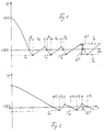
- Fig. 1 den Temperaturverlauf in einem Kühlraum über der Zeit bei geringer Last und
- Fig. 2 in entsprechender Darstellung den Temperaturverlauf bei hoher Last.
- Fig. 1 shows the temperature curve in a refrigerator over time at low load and
- Fig. 2 in a corresponding representation of the temperature profile at high load.
Im folgenden wird beispielsweise von einem Kühlaggregat ausgegangen, das zum Abtauen von Eis, das sich am Verdampfer gebildet hat, zunächst abgeschaltet ist und nach Erreichen der Abtauendtemperatur von beispielsweise 10°C wieder eingeschaltet wird, um den vorgegebenen Sollwert von beispielsweise -18°C in dem Kühlraum wiederherzustellen und beizubehalten, in dem das Kühlaggregat angeordnet ist.In the following, a cooling unit is assumed, for example, which is initially switched off for defrosting ice that has formed on the evaporator and is switched on again after the end of the defrosting temperature of, for example, 10 ° C., by the predetermined setpoint of, for example, -18 ° C. to restore and maintain the cold room in which the cooling unit is located.
Üblicherweise ist in dem zu kühlenden Raum ein Temperaturfühler angeordnet, der den in den Fig. 1 und 2 widergegebenen Temperaturverlauf im Kühlraum liefert.Usually, a temperature sensor is arranged in the room to be cooled, which provides the temperature profile in the cooling room shown in FIGS. 1 and 2.
Nach Beendigung der Abtauphase wird zum Zeitpunkt 0 in Fig. 1 das Kühlaggregat eingeschaltet, worauf nach einer bestimmten Zeit vorgegebene Sollwert von -18°C erreicht wird. Sobald die Temperatur im Kühlraum den Sollwert von -18°C erreicht, wird durch einen Zeitgeber eine Zeit t₁ in Lauf gesetzt, nach deren Ablauf die von Temperaturfühler festgestellte Temperatur abgefragt wird. Diese am Ende von t₁ abgefragte Temperatur Tx liegt um einen bestimmten Betrag unter dem Sollwert von -18°C. Die gemessene Temperatur Tx wird in einer elektronischen Einrichtung gespeichert. Zugleich wird das Kühlaggregat von der elektronischen Steuereinrichtung abgeschaltet, so daß die Temperatur am Temperaturfühler wieder ansteigt.After the defrost phase has ended, the cooling unit is switched on at time 0 in FIG. 1, after which a predetermined setpoint of -18 ° C. is reached after a certain time. As soon as the temperature in the refrigerator reaches the setpoint of -18 ° C, a timer t₁ is set in run by a timer, after which the temperature determined by the temperature sensor is queried. This at the end of t₁ queried temperature T x is a certain amount below the setpoint of -18 ° C. The measured temperature T x is stored in an electronic device. At the same time, the cooling unit is switched off by the electronic control device, so that the temperature at the temperature sensor rises again.
Mit dem Abschalten des Kühlaggregats wird eine Zeit t₂ in Lauf gesetzt, bei deren Ablauf am Temperaturfühler abgefragt wird, ob die Temperatur den Sollwert erreicht oder überschritten hat. Liegt die bei Ablauf von t₂ festgestellte Temperatur über dem Sollwert, so wird das Kühlaggregat wieder eingeschaltet, so daß die Temperatur am Temperaturfühler wieder absinkt. Sobald der Sollwert am Temperaturfühler festgestellt wird, wird erneut die Zeit t₁ in Lauf gesetzt und bei deren Ablauf die Temperatur am Temperaturfühler abgefragt. Wird beispielsweise eine Temperatur T′x unter dem Sollwert gemessen, so wird diese Temperatur T′x gespeichert und mit der zuvor gemessenen Temperatur Tx verglichen. Gleichzeitig wird das Kühlaggregat wider abgeschaltet und die Zeit t₂ in Lauf gesetzt.When the cooling unit is switched off, a time t 2 is started, when the temperature sensor expires, a query is made as to whether the temperature has reached or exceeded the setpoint. If the temperature determined when t₂ has expired is above the setpoint, the cooling unit is switched on again, so that the temperature at the temperature sensor drops again. As soon as the setpoint is determined on the temperature sensor, the time t 1 is started again and when it expires the temperature is queried on the temperature sensor. If, for example, a temperature T ' x is measured below the target value, this temperature T' x is stored and compared with the previously measured temperature T x . At the same time, the cooling unit is switched off again and the time t₂ started.
Ergibt der Vergleich daß Tx gleich T′x ist, so bleiben beide Temperaturen Tx und T′x gespeichert, worauf nach Ablauf von t₂ erneut abgefragt wird, ob die Temperatur den Sollwert erreicht oder überschritten hat. Ist dies der Fall, so wird das Kühlaggregat wieder eingeschaltet, worauf bei Erreichen des Sollwerts erneut die Zeit t₁ in Lauf gesetzt und bei deren Ablauf die Temperatur am Temperaturfühler abgefragt wird. Die Temperatur T˝x unter dem Sollwert wird wiederum gespeichert und mit beiden vorhergehenden Temperaturen Tx und T′x verglichen. Ergibt der Vergleich, daß alle drei Temperaturen gleich sind, so wird daraus abgeleitet, daß sich ein stabiler Zustand im Kühlraum eingestellt hat. Der Abfragezyklus wird abgebrochen und die Temperaturdifferenz ΔT zwischen Sollwert und Tx festgestellt, worauf die Temperaturdifferenz über und unter dem Sollwert als Grenzwert zum Ein- und Abschalten des Kühlaggregats festgelegt wird, wie dies in Fig. 1 durch gestrichelte Linien über und unter dem Sollwert bei Te und Ta angedeutet ist. Nachdem das Kühlaggregat beim Abfragen von T˝x abgeschaltet wurde, steigt die Temperatur am Temperaturfühler nach einer gewissen Zeit wieder über den Sollwert, worauf aber erst bei Erreichen des oberen Grenzwertes Te das Kühlaggregat wieder eingeschaltet wird, der um den Betrag ΔT über dem Sollwert liegt. Im weiteren Verlauf des Kühlbetriebs wird das Kühlaggregat erst dann wieder abgeschaltet, wenn am Temperaturfühler der untere Grenzwert Ta festgestellt wird, der um den Betrag ΔT unter dem Sollwert liegt. Die Temperaturdifferenz von 2ΔT zwischen Ein- und Ausschalttemperatur Te und Ta beiderseits des Sollwertes wird bis zum nächsten Abtauvorgang des Kühlaggregats oder bis zur nächsten Betriebsänderung beibehalten, worauf bei Neubeginn einer weiteren Betriebsphase des Kühlaggregats der beschriebene Vorgang wiederholt wird, um erneut die Temperaturdifferenz 2ΔT zu bestimmen und für den weiteren Betrieb festzulegen.If the comparison shows that T x is equal to T ' x , then both temperatures T x and T' x remain stored, whereupon a query is made again after the end of t₂ whether the temperature has reached or exceeded the setpoint. If this is the case, the cooling unit is switched on again, whereupon the time t 1 is started again when the setpoint is reached and when the temperature expires the temperature sensor is queried. The temperature T˝ x below the setpoint is again stored and compared with the two previous temperatures T x and T ' x . If the comparison shows that all three temperatures are the same, it is deduced from this that a stable state has occurred in the refrigerator compartment. The interrogation cycle is terminated and the temperature difference ΔT between the setpoint and T x is determined, whereupon the temperature difference above and below the setpoint is set as the limit for switching the cooling unit on and off, as shown in FIG. 1 by dashed lines above and below the setpoint T e and T a is indicated. After the cooling unit has been switched off when querying T˝ x , the temperature at the temperature sensor rises above the setpoint again after a certain time, but then the cooling unit is only switched on again when the upper limit value T e is reached, which is ΔT above the setpoint lies. In the further course of the cooling operation, the cooling unit is only switched off again when the lower limit value T a is determined on the temperature sensor, which is below the target value by the amount ΔT. The temperature difference of 2ΔT between the switch-on and switch-off temperatures T e and T a on both sides of the setpoint is maintained until the next defrosting process of the cooling unit or until the next change in operation, whereupon the described process is repeated when a new operating phase of the cooling unit starts again, again by the temperature difference 2ΔT to be determined and determined for further operation.
Wird bei dem Vergleich der Temperatur T˝x mit den beiden vorhergehenden Temperaturen Tx und T′x beispielsweise festgestellt, daß T˝x kleiner oder größer ist als die vorhergehenden Werte, so werden die vorhergehenden Temperaturen Tx und T′x im Speicher der elektronischen Steuereinrichtung gelöscht, wobei lediglich der Wert T˝x im Speicher beibehalten wird. Hierauf wird ausgehend von der Temperatur T˝x der Abfragevorgang so lange wiederholt, bis eine Sequenz von drei gleichen Temperatren Tx festgestellt wird. Solange drei aufeinanderfolgende Werte Tx nicht gleich sind, wird davon ausgegangen, daß sich noch kein stabiler Zustand im Kühlraum eingestellt hat. Anstelle von drei aufeinanderfolgenden Werten Tx können auch zwei oder vier oder mehrere vorgegeben werden, die zum Erkennen eines stabilen Zustandes und zum Festlegen der Temperaturdifferenz 2ΔT gleich sein müssen.If, when comparing the temperature T˝ x with the two previous temperatures T x and T ' x, for example, it is found that T˝ x is smaller or larger than the previous values, the previous temperatures T x and T' x are stored in the memory electronic control device deleted, only the value T˝ x is retained in the memory. Based on the temperature T˝ x, the query process is repeated until a sequence of three identical temperatures T x is determined. As long as three successive values T x are not the same, it is assumed that a stable state has not yet occurred in the cold room. Instead of three successive values T x , two or four or more can also be specified, which must be the same in order to recognize a stable state and to determine the temperature difference 2ΔT.
Bei einem Kühlaggregat ist üblicherweise eine Wiederanlaufsperre in Form eines Zeitrelais vorgesehen, das nach dem Abschalten des Aggregats ein Wiedereinschalten erst dan zuläßt. wenn eine vorbestimmte Zeit von besipielsweise 180 s verstrichen ist. Durch eine derartige Wiederanlaufsperre wird der Motor des Kühlaggregats vor einer Beschädigung durch zu hohe Schalthäufigkeit geschützt. Die bei dem vorausgehenden Beispiel angegebene Zeit t₂ muß deshalb größer oder gleich der Zeit von beispielsweise 180 s der Wiederanlaufsperre sein.In the case of a cooling unit, a restart interlock in the form of a time relay is usually provided, which only then permits restarting after the unit has been switched off. when a predetermined time of 180 s has elapsed, for example. Such a restart interlock protects the motor of the cooling unit from damage caused by an excessive number of starts. The time t₂ given in the preceding example must therefore be greater than or equal to the time of, for example, 180 s of the restart interlock.
Anstelle einer vorgegebenen Zeit t₂ ist es auch möglich, nach Ablauf der Wiederanlaufsperre von beispielsweise 180 s nach Ablauf von t₁ in kurzen Zeitabständen die Temperatur am Temperaturfühler abzufragen, worauf das Kühlaggregat wieder eingeschaltet wird, sobald eine Temperatur am oder über dem Sollwert festgestellt wird.Instead of a predetermined time t₂, it is also possible to query the temperature at the temperature sensor at short intervals after the restart interlock of, for example, 180 s after the end of t₁, whereupon the cooling unit is switched on again as soon as a temperature at or above the setpoint is determined.
Die Zeit t₁ kann beispielsweise auf 300 s eingestellt werden. Es ist aber auch möglich, t₁ auf beispielsweise 180 s festzulegen, wobei die von Aggregathersteller vorgegebene Mindestlaufzeit zu berücksichtigen ist.The time t 1 can for example be set to 300 s. But it is also possible to set t₁ to, for example, 180 s, taking into account the minimum runtime specified by the unit manufacturer.
Zweckmäßigerweise wird bei einem festgestellten Temperaturwert Tx eine Toleranzgrenze von beispielsweise +/- 0,5°C vorgegeben, innerhalb der ein folgender Meßwert T′x oder T˝x als gleich zu Tx angesehen wird. Wenn bei der zweiten oder dritten Messung der Vergleichswert außerhalb der Toleranz von +/- 0,5°C liegt, beispielsweise verursacht durch Belastungsschwankungen des Kühlraumes, so wird mit dem letzten Vergleichswert die zuvor beschriebene Folge von drei Messungen neu begonnen.For a determined temperature value T x, a tolerance limit of, for example, +/- 0.5 ° C. is expediently set, within which a following measured value T ′ x or T˝ x is regarded as being equal to T x . If, in the second or third measurement, the comparison value is outside the tolerance of +/- 0.5 ° C, for example caused by load fluctuations in the refrigerator, the sequence of three measurements described above is started again with the last comparison value.
Während sich bei einer geringen Kühllast ein relativ großes ΔT nach Ablauf von t₁ ergibt, erhält man bei großer Kühllast nach Ablauf von t₁ ein kleines ΔT, wie dies aus einem Vergleich der Fig. 1 und 2 ersichtlich ist, wobei Fig. 1 in etwa den Temperaturverlauf bei geringer Kühllast und Fig. 2 den Temperaturverlauf bei hoher Kühllast wiedergibt. Entsprechend wird durch das beschriebene Verfahren die Temperaturdifferenz zwischen Einschalttemperatur Te und Ausschalttemperatur Ta in Abhängigkeit vom Belastungszustand des Kühlaggregats eingestellt und damit auch die Schalthäufigkeit des Kühlaggregats dem Belastungszustand angepaßt. Im Gegensatz dazu wird im Stand der Technik die Temperaturdifferenze zwischen Einschalttemperatur Te und Ausschalttemperatur Ta vom Anlagenbauer nach Gefühl eingestellt, wobei diese fest eingestellte Temperaturdifferenz allenfalls einem Betriebszustand in etwa entspricht, nicht aber den während des Betriebs einer Kühlanlage auftretenden, variierenden Betriebszuständen.While there is a relatively large ΔT after a t₁ at a low cooling load, a small ΔT is obtained after a t₁ at a large cooling load, as can be seen from a comparison of FIGS. 1 and 2, with FIG. 1 approximately Temperature curve at low cooling load and Fig. 2 shows the temperature curve at high cooling load. Correspondingly, the temperature difference between the switch-on temperature T e and the switch-off temperature T a is set as a function of the load condition of the cooling unit and the switching frequency of the cooling unit is thus adapted to the load state by the described method. In contrast to this, in the prior art the temperature difference between the switch-on temperature T e and the switch-off temperature T a is set by the system builder by feel, whereby this permanently set temperature difference corresponds at most to an operating state, but not to the varying operating states that occur during the operation of a cooling system.
Die automatische Anpassung der Temperaturdifferenz zwischen Ein- und Ausschalttemperatur bzw. der Schalthäufigkeit an den Belastungszustand wird bei einer Kühlanlage zweckmäßigerweise nach jedem Abtauvorgang vorgenommen, der erfahrungsgemäß alle 8 bis 24 Stunden abläuft.The automatic adjustment of the temperature difference between the switch-on and switch-off temperature or the switching frequency to the load condition is expediently carried out in a cooling system after each defrosting process, which experience has shown to occur every 8 to 24 hours.
Bei häufig wechselnder Kühllast kommt das beschriebene Steuerverfahren nicht zum Einsatz, vielmehr nur dann, wenn über längere Zeiträume etwa gleichbleibende Temperaturzustände vorhanden sind. Dies ist üblicherweise nach dem Abtauen bei Kühlanlagen der Fall.If the cooling load changes frequently, the control method described is not used, but rather only if the temperature conditions remain constant over longer periods of time. This is usually the case after defrosting in cooling systems.
Da bei einem Kühlaggregat der Druck auf der Saugseite des Kompressors abhängig ist von der Temperatur im Verdampfer, ist es auch möglich, anstelle einer Temperaturmessung im Verdampfer eine Druckmessung vorzunehmen und anhand des vom Druckfühler gelieferten elektrischen Signals das zuvor beschriebene Steuerverfahren durchzuführen, wobei das vom Druckfühler gelieferte elektrische Signal im wesentlichen dem Verlauf des Temperatursignals in den Fig. 1 und 2 entspricht.Since the pressure on the suction side of the compressor in a cooling unit depends on the temperature in the evaporator, it is also possible to carry out a pressure measurement instead of a temperature measurement in the evaporator and to carry out the control method described above on the basis of the electrical signal supplied by the pressure sensor, this being done by the pressure sensor delivered electrical signal essentially corresponds to the course of the temperature signal in FIGS. 1 and 2.
Das Steuerverfahren wurde anhand eines Kühlaggregats beschrieben, es ist aber auch möglich, in gleicher Weise ein Heizaggregat zu steuern, insbesondere im Zusammenhang mit einer Wärmepumpe, wobei in Abhängigkeit von der vorhandenen Heizlast die Temperaturdifferenz zwischen Ein- und Ausschalttemperatur des Heizaggregats eingestellt wird. Hierbei liegen die gemessenen Temperaturwerte Tx über einem vorgegebenen Sollwert, wie auch die Ausschalttemperatur Ta über dem Sollwert und die Einschalttemperatur Te unter dem Sollwert liegt. Auch hierbei kann eine Raumtemperatur oder eine Medientemperatur abgefragt, gespeichert und verglichen werden, wie dies auch bei einem Kühlaggregat der Fall ist.The control process was described using a cooling unit, but it is also possible to control a heating unit in the same way, especially in connection with a heat pump, whereby the temperature difference between the heating unit's on and off temperature is set depending on the heating load. Here, the measured temperature values T x are above a predetermined target value, as are the switch-off temperature T a above the target value and the switch-on temperature T e below the target value. Here too, a room temperature or a media temperature can be queried, stored and compared, as is also the case with a cooling unit.
Im Falle der Überwachung einer Medientemperatur kann beispielsweise die Wassertemperatur in einem Boiler oder die Öltemperatur in einem Ölkühler im Zusammenhang mit einer Wärmepumpe gemessen werden.When monitoring a media temperature, for example, the water temperature in a boiler or the oil temperature in an oil cooler can be measured in connection with a heat pump.
Wenn beispielsweise im Falle eines Kühlaggregats von Anlagenbauer nach dem Stand der Technik eine unveränderliche Temperaturdifferenz zwischen Ein- und Ausschalttemperatur eingestellt wird und die Kühllast in dem auf eine bestimmte Kapazität ausgelegten Kühlraum erheblich unter der üblichen liegt, auf die die Temperaturdifferenz zwischen Ein- und Ausschalttemperatur ursprünglich abgestimmt wurde, so wird das Kühlaggregat in kurzen Zeitabständen ein- und ausgeschaltet, weil wegen der zu geringen Kühllast nach Erreichen von Te der Grenzwert Ta schneller erreicht wird. In einem solchen Falle kann das Kühlaggregat bis an die Schalthäufigkeitsgrenze und darüber ein- und ausgeschaltet werden. Dagegen wird durch das beschriebene Steuerverfahren spätestens nach einem Abtauvorgang eine neue, größere Temperaturdifferenz zwischen Ein- und Ausschalttemperatur bestimmt, so daß die Schalthäufigkeit selbsttätig verringert wird.If, for example, in the case of a cooling unit from plant builders according to the prior art, an invariable temperature difference between the switch-on and switch-off temperature is set and the cooling load in the cooling space designed for a specific capacity is considerably below the usual to which the temperature difference between switch-on and switch-off temperature originally was was tuned, the cooling unit is switched on and off at short intervals, because the limit value T a is reached more quickly after reaching T e due to the insufficient cooling load. In such a case, the cooling unit can be switched on and off up to the switching frequency limit and above. In contrast, the control method described determines a new, larger temperature difference between the switch-on and switch-off temperatures at the latest after a defrosting process, so that the switching frequency is automatically reduced.
Es is auch möglich, beispielsweise die Schalthäufigkeit des Kühlaggregats in deren Grenzbereich zu überwachen und den beschriebenen Abfragezyklus dann einzuleiten, wenn eine hohe Schalthäufigkeit festgestellt wird, so daß ein Abtauvorgang nicht abgewartet werden muß. In gleicher Weise ist es möglich, bei einer anderen Änderung des Belastungszustandes des Aggregats den Abfragezyklus einzuleiten, oder in bestimmten Zeitabständen den Zustand abzufragen und bei einer Änderung des Betriebszustandes den Abfragezyklus wieder zu beginnen.It is also possible, for example, to monitor the switching frequency of the cooling unit in its limit range and to initiate the described polling cycle when a high switching frequency is determined, so that a defrosting process does not have to be waited for. In the same way, it is possible to initiate the polling cycle when there is another change in the load condition of the unit, or to poll the status at certain time intervals and to start the polling cycle again when the operating condition changes.
Claims (6)
dadurch gekennzeichnet,
daß man wiederholt die Temperatur ermittelt, die ausgehend von dem Sollwert jeweils nach Ablauf einer vorgegebenen Zeiteinheit von dem Aggregat unter bzw. über dem Sollwert erreicht wird, diese ermittelten Temperaturen vergleicht und jene Temperatur zur Einstellung der Temperaturdifferenz zwischen Ein- und Ausschalttemperatur verwendet, die mit mehreren vorhergehend gemessenen Temperaturen übereinstimmt.1. Method for setting the temperature difference between the switch-on and switch-off temperature of a heating unit or in particular a cooling unit in the range of a setpoint temperature of a medium or a room to be maintained,
characterized by
that one repeatedly determines the temperature, based on the setpoint each time a predetermined unit of time is reached by the unit below or above the setpoint, compares these determined temperatures and uses that temperature for setting the temperature difference between the switch-on and switch-off temperatures that corresponds to several previously measured temperatures.
dadurch gekennzeichnet,
daß wenigstens bei jedem Neubeginn einer Betriebsperiode des Aggregats bei Erreichen des Sollwertes eine Zeit (t₁) in Lauf gesetzt wird, nach deren Ablauf die erreichte Temperatur abgefragt, gespeichert und das Aggregat abgeschaltet wird, worauf das Aggregat wieder eingeschaltet wird, nachdem die zu überwachende Temperatur bei abgeschaltetem Gerät den Sollwert erreicht oder überschritten hat, daß bei Erreichen des Sollwertes bei eingeschaltetem Aggregat die vorgegebene Zeit (t) wieder in Lauf gesetzt und nach deren Ablauf die erreichte Temperatur abgefragt, gespeichert und das Aggregat abgeschaltet wird, wobei die gemessene Temperatur (T′x) mit der vorher gemessenen Temperatur (Tx) verglichen wird, und daß diese Schritte so lange wiederholt werden, bis eine vorbestimmte Anzahl von aufeinanderfolgenden Temperaturwerten (Tx) gleich ist, worauf die Differenz zwischen dieser Temperatur (Tx) und dem sollwert festgestellt und diese Temperaturdifferenz über und unter dem Sollwert als Ein- und Ausschalttemperatur für den weiteren Betrieb des Aggregats beibehalten wird.2. The method according to claim 1,
characterized,
that at least each time a new operating period of the unit is reached when the setpoint is reached, a time (t 1) is set to run, after which the temperature reached is queried, stored and the unit is switched off, whereupon the unit is switched on again after the temperature to be monitored has reached or exceeded the setpoint when the device is switched off, that when the setpoint is reached with the aggregate switched on, the specified time (t) is started again and after the expiry of the temperature reached, saved and the aggregate is switched off, the measured temperature (T ' X ) is compared with the previously measured temperature (T x ), and that these steps are repeated until a predetermined number of successive temperature values (T x ) is equal, whereupon the difference between this temperature (T x ) and the setpoint and this temperature difference above and below the setpoint as Switch-on and switch-off temperature is maintained for the further operation of the unit.
dadurch gekennzeichnet,
daß für den Vergleich der gemessenen Temperaturen (Tx) ein Toleranzbereich um den gemessenen Temperaturwert vorgegeben wird, innerhalb dem ein erneut gemessener Temperaturwert (T′x) als gleich bewertet wird.3. The method according to claims 1 and 2,
characterized,
that for the comparison of the measured temperatures (T x ) a tolerance range around the measured temperature value is specified, within which a measured again Temperature value (T ′ x ) is rated as the same.
dadurch gekennzeichnet,
daß jeweils drei aufeinanderfolgend gleiche Temperaturwerte (Tx) für die Einstellung der Temperaturdifferenz zwischen Ein- und Ausschalttemperatur verwendet werden.4. The method according to claims 1 to 3,
characterized,
that three successively identical temperature values (T x ) are used to set the temperature difference between the switch-on and switch-off temperatures.
dadurch gekennzeichnet,
daß bei aufeinanderfolgend ungleichen Temperaturen (Tx) der zuletzt gemessene Temperaturwert gespeichert und der oder die vorher gemessenen Temperaturwerte gelöscht werden, worauf mit dem zuletzt gemessenen Temperaturwert der Zyklus erneut beginnt.5. The method according to claims 1 to 4,
characterized,
that in the case of successively unequal temperatures (T x ) the last measured temperature value is saved and the previously measured temperature value (s) are deleted, whereupon the cycle begins again with the last measured temperature value.
dadurch gekennzeichnet,
daß eine elektronische Steuereinrichtung mit einem Speicher, einem Zeitgeber und einer Vergleichseinheit vorgesehen ist, die mit einem Temperaturfühler zur Abgabe von elektrischen Signalen und einer Einrichtung zum Ein- und Ausschalten des Aggregats in Abhängigkeit von Steuersignalen von der Steuereinrichtung verbunden ist.6. Device for performing the method according to claims 1 to 5,
characterized,
that an electronic control device with a memory, a timer and a comparison unit is provided, which is connected to a temperature sensor for emitting electrical signals and a device for switching the unit on and off as a function of control signals from the control device.
Priority Applications (1)
| Application Number | Priority Date | Filing Date | Title |
|---|---|---|---|
| AT89102436T ATE95326T1 (en) | 1988-02-11 | 1989-02-13 | METHOD OF ADJUSTING THE TEMPERATURE DIFFERENCE BETWEEN THE ON AND OFF TEMPERATURE OF A REFRIGERATION UNIT. |
Applications Claiming Priority (2)
| Application Number | Priority Date | Filing Date | Title |
|---|---|---|---|
| DE3804258A DE3804258C1 (en) | 1988-02-11 | 1988-02-11 | |
| DE3804258 | 1988-02-11 |
Publications (3)
| Publication Number | Publication Date |
|---|---|
| EP0336076A2 true EP0336076A2 (en) | 1989-10-11 |
| EP0336076A3 EP0336076A3 (en) | 1990-05-23 |
| EP0336076B1 EP0336076B1 (en) | 1993-09-29 |
Family
ID=6347204
Family Applications (1)
| Application Number | Title | Priority Date | Filing Date |
|---|---|---|---|
| EP89102436A Expired - Lifetime EP0336076B1 (en) | 1988-02-11 | 1989-02-13 | Adjusting method for the temperature difference between switch-on and switch-off temperatures of a cooling device |
Country Status (5)
| Country | Link |
|---|---|
| US (1) | US4934593A (en) |
| EP (1) | EP0336076B1 (en) |
| JP (1) | JPH01266609A (en) |
| AT (1) | ATE95326T1 (en) |
| DE (1) | DE3804258C1 (en) |
Families Citing this family (18)
| Publication number | Priority date | Publication date | Assignee | Title |
|---|---|---|---|---|
| US5197670A (en) * | 1991-10-24 | 1993-03-30 | Thermo King Corporation | Method of operating a transport refrigeration unit |
| DE4445191C2 (en) * | 1994-12-17 | 1999-07-22 | Eberspaecher J Gmbh & Co | Method for controlling a heater |
| KR0180596B1 (en) * | 1995-05-10 | 1999-05-01 | 정몽원 | Temperature compensation method of storage with deep freezer |
| KR0162404B1 (en) * | 1995-09-22 | 1999-01-15 | 구자홍 | Awakening control method of airconditioner |
| KR970028212A (en) * | 1995-11-24 | 1997-06-24 | 구자홍 | Awakening Air Conditioning Control Method for Air Conditioning |
| DE19725868C2 (en) * | 1997-06-18 | 1999-04-15 | Liebherr Hausgeraete | Method for displaying the temperature of a refrigerator and / or freezer |
| SE513258C2 (en) * | 1998-11-05 | 2000-08-07 | Electrolux Ab | Method and apparatus for controlling a temperature in a cabinet |
| JP4571762B2 (en) * | 2001-07-13 | 2010-10-27 | 株式会社リコー | Sardip type solid-state image sensor |
| US7270098B2 (en) * | 2002-07-15 | 2007-09-18 | Teleflex Canada Inc. | Vehicle heater and controls therefor |
| US6766962B2 (en) * | 2002-07-15 | 2004-07-27 | Teleflex Canada Limited Partnership | Temperature maintaining apparatus and temperature control apparatus and method therefor |
| US6772722B2 (en) | 2002-07-15 | 2004-08-10 | Teleflex Canada Limited Partnership | Heater and burner head assembly and control module therefor |
| US7337620B2 (en) * | 2005-05-18 | 2008-03-04 | Whirlpool Corporation | Insulated ice compartment for bottom mount refrigerator |
| JP5254559B2 (en) * | 2007-02-23 | 2013-08-07 | 三菱重工業株式会社 | Air conditioning apparatus and automatic heating operation control method |
| JP5116607B2 (en) * | 2008-08-18 | 2013-01-09 | 株式会社日立製作所 | Gas circuit breaker |
| JP5779108B2 (en) * | 2012-01-14 | 2015-09-16 | トミー工業株式会社 | Electrical equipment |
| DE102012002654A1 (en) * | 2012-02-10 | 2013-08-14 | Liebherr-Hausgeräte Ochsenhausen GmbH | Refrigerator and/or freezer e.g. chest freezer, has regulating unit that switches ON and/or OFF of compressor for temperature control within refrigerated compartment in response to correlated parameters of temperature in compartment |
| CN106959040B (en) * | 2017-04-28 | 2023-02-17 | 山东中实易通集团有限公司 | Air preheater cold end comprehensive temperature control method and system and air preheater |
| CN111365938B (en) * | 2020-03-20 | 2021-07-16 | 长虹美菱股份有限公司 | Method for accurately controlling temperature of warm storage of independent refrigerating system chamber |
Citations (3)
| Publication number | Priority date | Publication date | Assignee | Title |
|---|---|---|---|---|
| US4172555A (en) * | 1978-05-22 | 1979-10-30 | Levine Michael R | Adaptive electronic thermostat |
| DE3001844A1 (en) * | 1979-01-26 | 1980-07-31 | Elektrowatt Ag | METHOD AND CIRCUIT ARRANGEMENT FOR DETERMINING THE OPTIMAL SWITCH-ON TIME OF A HEATING OR AIR CONDITIONING |
| DE3145215A1 (en) * | 1980-11-14 | 1982-07-01 | Michael R. Ann Arbor Mich. Levine | THERMOSTAT DEVICE |
Family Cites Families (9)
| Publication number | Priority date | Publication date | Assignee | Title |
|---|---|---|---|---|
| US4257318A (en) * | 1979-04-30 | 1981-03-24 | Mcquay-Perfex Inc. | Variable dead band pressure control system |
| US4689967A (en) * | 1985-11-21 | 1987-09-01 | American Standard Inc. | Control and method for modulating the capacity of a temperature conditioning system |
| JPS56118114A (en) * | 1980-02-22 | 1981-09-17 | Matsushita Electric Ind Co Ltd | Temperature controller |
| US4325225A (en) * | 1980-07-28 | 1982-04-20 | Eaton Corporation | Electronic temperature control |
| US4373663A (en) * | 1981-12-10 | 1983-02-15 | Honeywell Inc. | Condition control system for efficient transfer of energy to and from a working fluid |
| DE3207815A1 (en) * | 1982-03-04 | 1983-09-15 | Siemens AG, 1000 Berlin und 8000 München | Control device for controlled systems with variable system gain |
| DE3516142C2 (en) * | 1984-05-29 | 1995-12-14 | Vaillant Joh Gmbh & Co | 2-point control method for a heat source |
| CH667147A5 (en) * | 1985-01-10 | 1988-09-15 | Landis & Gyr Ag | METHOD AND DEVICE FOR THE SELF-DETERMINATION OF THE DURATION OF A FAST-HEATING. |
| US4674027A (en) * | 1985-06-19 | 1987-06-16 | Honeywell Inc. | Thermostat means adaptively controlling the amount of overshoot or undershoot of space temperature |
-
1988
- 1988-02-11 DE DE3804258A patent/DE3804258C1/de not_active Expired
-
1989
- 1989-02-10 US US07/309,770 patent/US4934593A/en not_active Expired - Fee Related
- 1989-02-13 AT AT89102436T patent/ATE95326T1/en not_active IP Right Cessation
- 1989-02-13 EP EP89102436A patent/EP0336076B1/en not_active Expired - Lifetime
- 1989-02-13 JP JP1034867A patent/JPH01266609A/en active Pending
Patent Citations (3)
| Publication number | Priority date | Publication date | Assignee | Title |
|---|---|---|---|---|
| US4172555A (en) * | 1978-05-22 | 1979-10-30 | Levine Michael R | Adaptive electronic thermostat |
| DE3001844A1 (en) * | 1979-01-26 | 1980-07-31 | Elektrowatt Ag | METHOD AND CIRCUIT ARRANGEMENT FOR DETERMINING THE OPTIMAL SWITCH-ON TIME OF A HEATING OR AIR CONDITIONING |
| DE3145215A1 (en) * | 1980-11-14 | 1982-07-01 | Michael R. Ann Arbor Mich. Levine | THERMOSTAT DEVICE |
Also Published As
| Publication number | Publication date |
|---|---|
| JPH01266609A (en) | 1989-10-24 |
| DE3804258C1 (en) | 1989-09-14 |
| US4934593A (en) | 1990-06-19 |
| EP0336076B1 (en) | 1993-09-29 |
| ATE95326T1 (en) | 1993-10-15 |
| EP0336076A3 (en) | 1990-05-23 |
Similar Documents
| Publication | Publication Date | Title |
|---|---|---|
| EP0336076B1 (en) | Adjusting method for the temperature difference between switch-on and switch-off temperatures of a cooling device | |
| DE19828061C1 (en) | Method for controlling the temperature of a refrigerator and temperature control device for a refrigerator | |
| DE69817277T2 (en) | DEFROST CONTROL FOR HEAT PUMP | |
| DE3713869A1 (en) | CONTROL UNIT FOR THE OVERHEATING TEMPERATURE OF THE EVAPORATOR OF A REFRIGERATION OR HEAT PUMP SYSTEM | |
| EP0410330A2 (en) | Method and apparatus for operating a refrigeration system | |
| EP0328151B1 (en) | Heating control method, particularly for a thawing device in a refrigeration installation | |
| DE3517218A1 (en) | METHOD FOR OPERATING A STEAM COMPRESSION REFRIGERATION SYSTEM AND ARRANGEMENT FOR CONTROLLING THE SAME | |
| DE2262039B2 (en) | Device for the automatic control of the defrosting of the evaporator of a refrigerator | |
| EP0142663A2 (en) | Defrost control method and device for heat pumps | |
| WO2008077778A1 (en) | Refrigeration device and method for controlling a refrigeration device | |
| EP0328152B1 (en) | Operation control method for a refrigeration unit | |
| EP0727628B1 (en) | Control system and method of temperature control for refrigerators | |
| DE4114700C2 (en) | ||
| EP0152608A2 (en) | Control method for a compound refrigeration plant | |
| DE2717050C3 (en) | Compressor refrigeration systems with two compartments of different temperatures | |
| DE102007045370A1 (en) | Method for determining a performance of a cooling system | |
| EP1813897A2 (en) | Method for regulating a cooling appliance | |
| DE102015104843A1 (en) | Control method for a control cabinet cooling unit | |
| DE3209509A1 (en) | COOLING MACHINE WITH A MOTOR-COMPRESSOR MODULE | |
| CH691236A5 (en) | Method for operating a household refrigerator. | |
| EP1178271B1 (en) | Electronic control device for cooling or freezing apparatus | |
| EP2652409B1 (en) | Method for operating a heat pump device | |
| EP2810003B1 (en) | Refrigeration device having two storage chambers | |
| DE4006468C1 (en) | Defroster for refrigerator using compressor motor - supplied with electricity via thermostat switch controlled by sensor and actuator | |
| DE3429380C2 (en) |
Legal Events
| Date | Code | Title | Description |
|---|---|---|---|
| PUAI | Public reference made under article 153(3) epc to a published international application that has entered the european phase |
Free format text: ORIGINAL CODE: 0009012 |
|
| AK | Designated contracting states |
Kind code of ref document: A2 Designated state(s): AT FR GB IT NL SE |
|
| PUAL | Search report despatched |
Free format text: ORIGINAL CODE: 0009013 |
|
| AK | Designated contracting states |
Kind code of ref document: A3 Designated state(s): AT FR GB IT NL SE |
|
| 17P | Request for examination filed |
Effective date: 19901015 |
|
| 17Q | First examination report despatched |
Effective date: 19920518 |
|
| GRAA | (expected) grant |
Free format text: ORIGINAL CODE: 0009210 |
|
| AK | Designated contracting states |
Kind code of ref document: B1 Designated state(s): AT FR GB IT NL SE |
|
| REF | Corresponds to: |
Ref document number: 95326 Country of ref document: AT Date of ref document: 19931015 Kind code of ref document: T |
|
| ITF | It: translation for a ep patent filed |
Owner name: BARZANO' E ZANARDO MILA |
|
| ET | Fr: translation filed | ||
| GBT | Gb: translation of ep patent filed (gb section 77(6)(a)/1977) |
Effective date: 19940125 |
|
| PLBE | No opposition filed within time limit |
Free format text: ORIGINAL CODE: 0009261 |
|
| STAA | Information on the status of an ep patent application or granted ep patent |
Free format text: STATUS: NO OPPOSITION FILED WITHIN TIME LIMIT |
|
| 26N | No opposition filed | ||
| EAL | Se: european patent in force in sweden |
Ref document number: 89102436.6 |
|
| PGFP | Annual fee paid to national office [announced via postgrant information from national office to epo] |
Ref country code: AT Payment date: 20010220 Year of fee payment: 13 |
|
| PGFP | Annual fee paid to national office [announced via postgrant information from national office to epo] |
Ref country code: SE Payment date: 20010221 Year of fee payment: 13 |
|
| REG | Reference to a national code |
Ref country code: GB Ref legal event code: IF02 |
|
| PG25 | Lapsed in a contracting state [announced via postgrant information from national office to epo] |
Ref country code: AT Free format text: LAPSE BECAUSE OF NON-PAYMENT OF DUE FEES Effective date: 20020213 |
|
| PG25 | Lapsed in a contracting state [announced via postgrant information from national office to epo] |
Ref country code: SE Free format text: LAPSE BECAUSE OF NON-PAYMENT OF DUE FEES Effective date: 20020214 |
|
| PGFP | Annual fee paid to national office [announced via postgrant information from national office to epo] |
Ref country code: FR Payment date: 20020221 Year of fee payment: 14 |
|
| PGFP | Annual fee paid to national office [announced via postgrant information from national office to epo] |
Ref country code: GB Payment date: 20020225 Year of fee payment: 14 |
|
| PGFP | Annual fee paid to national office [announced via postgrant information from national office to epo] |
Ref country code: NL Payment date: 20020226 Year of fee payment: 14 |
|
| EUG | Se: european patent has lapsed |
Ref document number: 89102436.6 |
|
| PG25 | Lapsed in a contracting state [announced via postgrant information from national office to epo] |
Ref country code: GB Free format text: LAPSE BECAUSE OF NON-PAYMENT OF DUE FEES Effective date: 20030213 |
|
| PG25 | Lapsed in a contracting state [announced via postgrant information from national office to epo] |
Ref country code: NL Free format text: LAPSE BECAUSE OF NON-PAYMENT OF DUE FEES Effective date: 20030901 |
|
| GBPC | Gb: european patent ceased through non-payment of renewal fee | ||
| PG25 | Lapsed in a contracting state [announced via postgrant information from national office to epo] |
Ref country code: FR Free format text: LAPSE BECAUSE OF NON-PAYMENT OF DUE FEES Effective date: 20031031 |
|
| NLV4 | Nl: lapsed or anulled due to non-payment of the annual fee |
Effective date: 20030901 |
|
| REG | Reference to a national code |
Ref country code: FR Ref legal event code: ST |
|
| PG25 | Lapsed in a contracting state [announced via postgrant information from national office to epo] |
Ref country code: IT Free format text: LAPSE BECAUSE OF NON-PAYMENT OF DUE FEES Effective date: 20050213 |
|
| PGFP | Annual fee paid to national office [announced via postgrant information from national office to epo] |
Ref country code: IT Payment date: 20070605 Year of fee payment: 19 |
|
| PGRI | Patent reinstated in contracting state [announced from national office to epo] |
Ref country code: IT Effective date: 20091201 |
|
| PGRI | Patent reinstated in contracting state [announced from national office to epo] |
Ref country code: IT Effective date: 20091201 |