EP0335771B1 - Antenna for a nuclear magnetic resonance imaging apparatus - Google Patents
Antenna for a nuclear magnetic resonance imaging apparatus Download PDFInfo
- Publication number
- EP0335771B1 EP0335771B1 EP89400782A EP89400782A EP0335771B1 EP 0335771 B1 EP0335771 B1 EP 0335771B1 EP 89400782 A EP89400782 A EP 89400782A EP 89400782 A EP89400782 A EP 89400782A EP 0335771 B1 EP0335771 B1 EP 0335771B1
- Authority
- EP
- European Patent Office
- Prior art keywords
- turns
- plates
- antenna according
- antenna
- fixing
- Prior art date
- Legal status (The legal status is an assumption and is not a legal conclusion. Google has not performed a legal analysis and makes no representation as to the accuracy of the status listed.)
- Expired - Lifetime
Links
Images

Classifications
-
- G—PHYSICS
- G01—MEASURING; TESTING
- G01R—MEASURING ELECTRIC VARIABLES; MEASURING MAGNETIC VARIABLES
- G01R33/00—Arrangements or instruments for measuring magnetic variables
- G01R33/20—Arrangements or instruments for measuring magnetic variables involving magnetic resonance
- G01R33/28—Details of apparatus provided for in groups G01R33/44 - G01R33/64
- G01R33/32—Excitation or detection systems, e.g. using radio frequency signals
- G01R33/34—Constructional details, e.g. resonators, specially adapted to MR
- G01R33/34046—Volume type coils, e.g. bird-cage coils; Quadrature bird-cage coils; Circularly polarised coils
- G01R33/34061—Helmholtz coils
Definitions
- the present invention relates to nuclear magnetic resonance imaging devices such as those which are used in medical establishments for taking images of certain internal parts of the human body, in particular the brain, more particularly the examination of the brain and the bulbo-medullary hinge, for example, to detect possible tumors.
- such a device comprises, on a frame, a magnet comprising a magnetic field generator whose forces are all oriented in the same direction.
- This generator is generally constituted by a plurality of turns wound one next to the other to form a magnetic coil defining in its center a free space in which develops the lines of force of a homogeneous magnetic field called "main".
- the device also comprises, in association with the magnet, a support for the body of a patient, for example a bed mounted on means making it possible to move this bed in a direction parallel to that of the lines of force of the magnetic field given by the coil and in the center of it.
- a support for the body of a patient for example a bed mounted on means making it possible to move this bed in a direction parallel to that of the lines of force of the magnetic field given by the coil and in the center of it.
- This longitudinal static magnetic field generator is associated with means for creating other magnetic fields having gradients and which can be oriented in, for example, three directions in the space occupied by the volume of the part of the body to be examined and of which it is necessary to form the image, for example the brain in the example given above, means of excitation at a radio frequency, and means of detection of the nuclear magnetic resonance signals produced by some of the atoms of the part of the body analyzed.
- the excitation and detection means may consist of the same sensor part, only the input means of this sensor changing according to the desired function, either excitation or detection.
- Technicians are accustomed to naming this type of sensor by the term "antenna” (see, for example, EP-A-232 189).
- These antennas can take different structures generally making it possible to define a cylindrical zone able to be placed in the center of the magnetic coil and, moreover, so that its axis has the same direction as the main magnetic field defined above. However, to be fully effective, this cylindrical area must surround the body part to be analyzed, and as close as possible.
- the object of the present invention is to provide a nuclear magnetic resonance imaging device, and more particularly its "antenna" element, which is of a structure allowing it to adapt very easily to the needs of image production. of the body part to be analyzed and to this part of the body itself by surrounding it as closely as possible, and to create secondary magnetic fields having different orientations relative to the main magnetic field generated by the magnet.
- the subject of the present invention is an antenna for a nuclear magnetic resonance imaging device, characterized in that it comprises: two support plates made of electrically insulating material, spacer means for maintaining the two said plates at a determined distance from each other in two substantially parallel planes, clip-on - clip-on fixing means for at least one of the two said plates with said spacer means, at least two first and second turns of electrically conductive material, means for fixing said turns respectively on one face of the two said plates so as to form two current loops centered substantially on the same axis substantially perpendicular to said faces of said plates, and capacitive coupling means of the ends of each current loop.
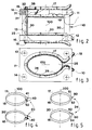
- FIGS. 1 to 5 represent the same embodiment of an antenna for a nuclear magnetic resonance imaging device, the same references designate the same elements therein.
- Figure 1 is shown, in schematic form, a device for making images of parts of the human body, commonly referred to as "scaner” by technicians.
- Such a device 1 comprises, on a frame 2, a magnet 3, the term "magnet” being taken in its broadest sense, that is to say representing both permanent magnets and magnets of the electromagnetic type. .
- this magnet 3 comprises a generator 4 of a magnetic field whose forces are all oriented in the same direction 5.
- This generator 4 is generally constituted by a plurality of turns wound next to each other to forming a magnetic coil defining at its center 6 a free space in which the lines of force of the so-called "main” homogeneous magnetic field develop.
- the device 1 additionally comprises, in association with the magnet 3, a support 7 for the body of a patient, for example a bed mounted on means 8 making it possible to move it in a direction parallel to that 5 of the lines of force of the magnetic field given by the coil 4, at the center of the space 6 defined by this coil, in its magnetic field.
- This longitudinal main magnetic field generator is associated with means 9 for creating secondary magnetic fields having gradients and which can be oriented in, for example, three directions in the space occupied by the volume of the part of the body to be examined and of which it is necessary to form the image, for example the brain, means of excitation at a radio frequency, and means of detection of the nuclear magnetic resonance signals produced by some of the atoms of the part of the body analyzed.
- excitation and detection means can be constituted by the same sensor part, only the input means of this sensor changing according to the desired function, either the excitation or the detection.
- Technicians are accustomed to naming such a sensor under the term "antenna" 10.
- the antenna 10 makes it possible to define a cylindrical zone able to be placed in the center of the main magnetic coil 4 and, according to the illustrated embodiment, comprises two support plates 11, 12 made of an electrically insulating material, for example plastic .
- spacer means are associated with clip-on - clip-on fixing means 14 with at least one of the two plates.
- first 17 and second 18 turns of electrically conductive material On one face 15, 16 of the two plates are respectively located at least two first 17 and second 18 turns of electrically conductive material, and, very advantageously, two third 19 and fourth 20 turns are respectively fixed on the two other faces 21, 22 of the two plates 11, 12, opposite the faces 15 and 16 respectively.
- Such a structure makes it possible to produce two current loops adaptable by which it is possible to obtain a secondary magnetic field whose lines of force have a direction perpendicular to the direction 5 of the lines of force of the main magnetic field.
- the antenna 10 further comprises either first capacitive coupling means 23 for coupling the two ends of each of the turns 17 - 20, as shown in FIG. 4, or second capacitive coupling means 24, as shown in FIG. 5, from one end of the first turn 17 with one end of the third 19, and from one end of the second 18 with one end of the fourth 20, the other ends being connected in pairs to form two loops of two each turns.
- the antenna comprises means 29, such as links, surrounding the conductors forming these turns and the ends of which are fixed on the plates, to secure the turns respectively on the faces of the two plates so that the current loops are centered substantially on the same axis 100 substantially perpendicular to the faces of these plates.
- an antenna as described above is particularly suitable for imaging the human brain.
- at least one of the two plates for example the plate 11 intended to surround the upper part of the patient's face, includes a cutout 25, and the (or la) turns 17, 19 associated with the plate 11 are then substantially located on the edge 26 of this cutout ( Figure 3).
- the length of the spacer means 13 is less than the thickness of the patient's head of which it is necessary to form an image, so that the edge 26 of the cutout 25 surrounds the face of the patient when the back of his head rests on the other plate 12.
- the second plate 12 can also include a cutout like that 25 produced in the plate 11 and the turns 18, 20 which are associated with it are located on the edge of this cutout.
- FIG. 2 a patient head surrounded by a antenna according to the invention making it possible to clearly highlight the fact that the high and low turns perfectly surround the brain of the patient to be examined as closely as possible.
- the spacer means 13 being constituted, for example, by several spacers 30, for example four, the fixing means 14 comprise a male lug 31 secured, in this embodiment, to one end of the spacers 30 and a female orifice complementary 32 produced in the other element, in this case the plate 11, in which the lug 31 can be inserted.
- the structure described above makes it possible to adapt different high and low current loops and to arrange the two plates on which they are located at different distances from each other, so as to create a secondary magnetic field perpendicular to the field. and better meet the needs of the role of the antenna.
- FIG. 4 represents a first embodiment of the capacitive coupling means.
- the coupling means 23 are constituted by an electric capacitor 40, the two terminals 41, 42 of which are respectively connected to the two ends of a turn.
- This embodiment of the capacitive coupling means therefore requires the use of a capacitor per turn, but allows to obtain several combinations, for example two loops, a high and a low, or four loops, two high and two low, mounted in parallel.
- FIG. 5 illustrates, for its part, a second possible embodiment of these coupling means 24 constituted, in this case, by two electric capacitors 50 whose terminals 51, 52 - 53, 54 are respectively connected to one end of each of the two first 17 and third 19 turns and at one end of each of the two second 18 and fourth 20 turns, the other ends of these turns being electrically connected in pairs to form two loops of two turns each.
- These coupling means 24 make it possible to obtain a greater self-value than in the mode according to the figure 4.
- the two ends of a turn are curved towards the outside of this turn, so as to create between them a space for the passage of the patient's neck. If the antenna has two pairs of turns, the ends of these turns are then arranged to generate a homogeneous secondary magnetic field.
- the two ends of a turn located on one side of a plate are substantially parallel to the two corresponding ends of the turn located on the other side of the same plate, as illustrated in FIG. 2.
- plate used in the preceding description should be understood as representing any support making it possible to maintain the first and third turns, on the one hand, and the second and fourth, on the other hand, substantially in two planes to a determined distance from each other.
Abstract
Description
La présente invention concerne les dispositifs d'imagerie par résonance magnétique nucléaire comme ceux qui sont utilisés dans les établissements médicaux pour réaliser des images de certaines parties internes du corps humain, notamment le cerveau, plus particulièrement l'examen de l'encéphale et de la charnière bulbo-médullaire en vue, par exemple, de déceler d'éventuelles tumeurs.The present invention relates to nuclear magnetic resonance imaging devices such as those which are used in medical establishments for taking images of certain internal parts of the human body, in particular the brain, more particularly the examination of the brain and the bulbo-medullary hinge, for example, to detect possible tumors.
Ces dispositifs sont déjà bien connus et relativement couramment utilisés malgré leur coût élevé. Très schématiquement, un tel dispositif comprend, sur un bâti, un aimant comprenant un générateur de champ magnétique dont les forces sont toutes orientées suivant la même direction. Ce générateur est généralement constitué par une pluralité de spires enroulées les unes à côté des autres pour former une bobine magnétique définissant en son centre un espace libre dans lequel se développe les lignes de force d'un champ magnétique homogène dit "principal".These devices are already well known and relatively commonly used despite their high cost. Very schematically, such a device comprises, on a frame, a magnet comprising a magnetic field generator whose forces are all oriented in the same direction. This generator is generally constituted by a plurality of turns wound one next to the other to form a magnetic coil defining in its center a free space in which develops the lines of force of a homogeneous magnetic field called "main".
Le dispositif comporte en plus, en association avec l'aimant, un support du corps d'un patient, par exemple un lit monté sur des moyens permettant de déplacer ce lit suivant une direction parallèle à celle des lignes de force du champ magnétique donné par la bobine et au centre de celle-ci.The device also comprises, in association with the magnet, a support for the body of a patient, for example a bed mounted on means making it possible to move this bed in a direction parallel to that of the lines of force of the magnetic field given by the coil and in the center of it.
A ce générateur de champ magnétique statique longitudinal sont associés des moyens pour créer d'autres champs magnétiques ayant des gradients et pouvant être orientés suivant, par exemple, trois directions dans l'espace occupé par le volume de la partie du corps à examiner et dont il est nécessaire de former l'image, par exemple le cerveau dans l'exemple donné ci-avant, des moyens d'excitation à une fréquence radio, et des moyens de détection des signaux de résonance magnétique nucléaire produits par certains des atomes de la partie du corps analysée.This longitudinal static magnetic field generator is associated with means for creating other magnetic fields having gradients and which can be oriented in, for example, three directions in the space occupied by the volume of the part of the body to be examined and of which it is necessary to form the image, for example the brain in the example given above, means of excitation at a radio frequency, and means of detection of the nuclear magnetic resonance signals produced by some of the atoms of the part of the body analyzed.
Il est d'ailleurs à préciser que, dans certains dispositifs, les moyens d'excitation et de détection peuvent être constitués par une même partie de capteur, seuls les moyens d'entrée de ce capteur changeant selon la fonction désirée, soit l'excitation, soit la détection. Les techniciens ont l'habitude de dénommer ce type de capteur par le vocable "antenne" (voir, par exemple, EP-A- 232 189).It should also be noted that, in certain devices, the excitation and detection means may consist of the same sensor part, only the input means of this sensor changing according to the desired function, either excitation or detection. Technicians are accustomed to naming this type of sensor by the term "antenna" (see, for example, EP-A-232 189).
Ces antennes peuvent prendre différentes structures permettant généralement de définir une zone cylindrique apte à être placée au centre de la bobine magnétique et, de plus, de façon que son axe ait la même direction que le champ magnétique principal défini ci-avant. Cependant, pour pouvoir être pleinement efficace, cette zone cylindrique doit entourer la partie du corps à analyser, et au plus près.These antennas can take different structures generally making it possible to define a cylindrical zone able to be placed in the center of the magnetic coil and, moreover, so that its axis has the same direction as the main magnetic field defined above. However, to be fully effective, this cylindrical area must surround the body part to be analyzed, and as close as possible.
Pour arriver à ce résultat, on a essayé de réaliser des structures de capteur particulières, mais, en fait, aucune d'elles n'a jamais donné une solution attrayante, c'est-à-dire facilitant l'installation du capteur dans le dispositif d'imagerie autour de la partie du corps du patient à analyser, en l'entourant au plus près.To achieve this, we tried to make particular sensor structures, but, in fact, none of them ever gave an attractive solution, that is to say facilitating the installation of the sensor in the imaging device around the part of the patient's body to be analyzed, surrounding it as closely as possible.
La présente invention a pour but de réaliser un dispositif d'imagerie par résonance magnétique nucléaire, et plus particulièrement son élément "antenne", qui soit d'une structure lui permettant de s'adapter très facilement aux besoins de la réalisation de l'image de la partie de corps à analyser et à cette partie du corps elle-même en l'entourant au plus près, et de créer des champs magnétiques secondaires ayant différentes orientations par rapport au champ magnétique principal engendré par l'aimant.The object of the present invention is to provide a nuclear magnetic resonance imaging device, and more particularly its "antenna" element, which is of a structure allowing it to adapt very easily to the needs of image production. of the body part to be analyzed and to this part of the body itself by surrounding it as closely as possible, and to create secondary magnetic fields having different orientations relative to the main magnetic field generated by the magnet.
Plus précisément, la présente invention a pour objet une antenne pour dispositif d'imagerie par résonance magnétique nucléaire, caractérisée par le fait qu'elle comprend :
deux plaques de support en matériau isolant électrique,
des moyens d'entretoise pour maintenir les deux dites plaques à une distance déterminée l'une de l'autre dans deux plans sensiblement parallèles,
des moyens de fixation enclipsables - déclipsables d'au moins une des deux dites plaques avec lesdits moyens d'entretoise,
au moins deux première et deuxième spires en matériau conducteur électrique,
des moyens pour fixer lesdites spires respectivement sur une face des deux dites plaques de façon à former deux boucles de courant centrées sensiblement sur un même axe sensiblement perpendiculaire auxdites faces desdites plaques, et
des moyens de couplage capacitifs des extrémités de chaque boucle de courant.More specifically, the subject of the present invention is an antenna for a nuclear magnetic resonance imaging device, characterized in that it comprises:
two support plates made of electrically insulating material,
spacer means for maintaining the two said plates at a determined distance from each other in two substantially parallel planes,
clip-on - clip-on fixing means for at least one of the two said plates with said spacer means,
at least two first and second turns of electrically conductive material,
means for fixing said turns respectively on one face of the two said plates so as to form two current loops centered substantially on the same axis substantially perpendicular to said faces of said plates, and
capacitive coupling means of the ends of each current loop.
D'autres caractéristiques et avantages de la présente invention apparaîtront au cours de la description suivante donnée en regard des dessins annexés à titre illustratif, mais nullement limitatif, dans lesquels :
- La figure 1 est une vue en perspective définissant de façon schématique les éléments essentiels d'un dispositif d'imagerie par résonance magnétique nucléaire, dans lequel apparaît un mode de réalisation de l'élément "antenne" selon l'invention,
- Les figures 2 et 3 représentent respectivement deux coupes perpendiculaires du mode de réalisation d'une antenne pour dispositif d'imagerie par résonance magnétique nucléaire selon l'invention, en accord avec la figure 1, et
- Les figures 4 et 5 représentent respectivement deux schémas électriques permettant de mettre en évidence un avantage de la structure d'antenne selon l'invention.
- FIG. 1 is a perspective view schematically defining the essential elements of an imaging device by nuclear magnetic resonance, in which an embodiment of the “antenna” element according to the invention appears,
- FIGS. 2 and 3 respectively represent two perpendicular sections of the embodiment of an antenna for a nuclear magnetic resonance imaging device according to the invention, in accordance with FIG. 1, and
- Figures 4 and 5 respectively represent two electrical diagrams to highlight an advantage of the antenna structure according to the invention.
Les figures 1 à 5 représentant le même mode de réalisation d'une antenne pour dispositif d'imagerie par résonance magnétique nucléaire, les mêmes références y désignent les mêmes éléments.FIGS. 1 to 5 represent the same embodiment of an antenna for a nuclear magnetic resonance imaging device, the same references designate the same elements therein.
Sur la figure 1 on a représenté, sous forme schématique, un dispositif permettant de réaliser des images de parties du corps humain, couramment dénommé "scaner" par les techniciens.In Figure 1 is shown, in schematic form, a device for making images of parts of the human body, commonly referred to as "scaner" by technicians.
Un tel dispositif 1 comporte, sur un bâti 2, un aimant 3, le terme "aimant" étant pris dans son sens le plus large, c'est-à-dire représentant aussi bien les aimants permanents que les aimants du type électro-magnétiques. Dans le mode de réalisation choisi, cet aimant 3 comprend un générateur 4 d'un champ magnétique dont les forces sont toutes orientées suivant la même direction 5. Ce générateur 4 est généralement constitué par une pluralité de spires enroulées les unes à côté des autres pour former une bobine magnétique définissant en son centre 6 un espace libre dans lequel se développent les lignes de force du champ magnétique homogène dit "principal".Such a device 1 comprises, on a
Le dispositif 1 comporte en plus, en association avec l'aimant 3, un support 7 du corps d'un patient, par exemple un lit monté sur des moyens 8 permettant de le déplacer suivant une direction parallèle à celle 5 des lignes de force du champ magnétique donné par la bobine 4, au centre de l'espace 6 défini par cette bobine, dans son champ magnétique.The device 1 additionally comprises, in association with the
A ce générateur de champ magnétique principal longitudinal sont associés des moyens 9 pour créer des champs magnétiques secondaires ayant des gradients et pouvant être orientés suivant, par exemple, trois directions dans l'espace occupé par le volume de la partie du corps à examiner et dont il est nécessaire de former l'image, par exemple le cerveau, des moyens d'excitation à une fréquence radio, et des moyens de détection des signaux de résonance magnétique nucléaire produits par certains des atomes de la partie du corps analysée.This longitudinal main magnetic field generator is associated with means 9 for creating secondary magnetic fields having gradients and which can be oriented in, for example, three directions in the space occupied by the volume of the part of the body to be examined and of which it is necessary to form the image, for example the brain, means of excitation at a radio frequency, and means of detection of the nuclear magnetic resonance signals produced by some of the atoms of the part of the body analyzed.
Ces moyens d'excitation et de détection peuvent être constitués par une même partie de capteur, seuls les moyens d'entrée de ce capteur changeant selon la fonction désirée, soit l'excitation, soit la détection. Les techniciens ont l'habitude de dénommer un tel capteur sous le vocable "antenne" 10.These excitation and detection means can be constituted by the same sensor part, only the input means of this sensor changing according to the desired function, either the excitation or the detection. Technicians are accustomed to naming such a sensor under the term "antenna" 10.
L'antenne 10 permet de définir une zone cylindrique apte à être placée au centre de la bobine magnétique principale 4 et, selon le mode de réalisation illustré, comprend deux plaques de support 11, 12 en un matériau isolant électrique, par exemple en matière plastique.The
Ces deux plaques 11, 12 sont maintenues à une distance déterminée l'une de l'autre, et avantageusement dans deux plans sensiblement parallèles, par des moyens d'entretoise 13.These two
A ces moyens d'entretoise sont associés des moyens de fixation enclipsables - déclipsables 14 avec au moins l'une des deux plaques.These spacer means are associated with clip-on - clip-on fixing means 14 with at least one of the two plates.
Sur une face 15, 16 des deux plaques sont respectivement situées au moins deux première 17 et deuxième 18 spires en matériau conducteur électrique, et, très avantageusement, deux troisième 19 et quatrième 20 spires sont respectivement fixées sur les deux autres faces 21, 22 des deux plaques 11, 12, opposées respectivement aux faces 15 et 16.On one
Une telle structure permet de réaliser deux boucles de courant adaptables par lesquelles il est possible d'obtenir un champ magnétique secondaire dont les lignes de force ont une direction perpendiculaire à la direction 5 des lignes de force du champ magnétique principal.Such a structure makes it possible to produce two current loops adaptable by which it is possible to obtain a secondary magnetic field whose lines of force have a direction perpendicular to the
L'antenne 10 comprend en outre, soit des premiers moyens de couplage capacitifs 23 pour coupler les deux extrémités de chacune des spires 17 - 20, comme représenté sur la figure 4, soit des seconds moyens de couplage capacitifs 24, comme représenté sur la figure 5, d'une extrémité de la première spire 17 avec une extrémité de la troisième 19, et d'une extrémité de la deuxième 18 avec une extrémité de la quatrième 20, les autres extrémités étant reliées deux à deux pour former deux boucles de deux spires chacune.The
Bien entendu, l'antenne comprend des moyens 29, comme des liens, entourant les conducteurs formant ces spires et dont les extrémités sont fixées sur les plaques, pour solidariser les spires respectivement sur les faces des deux plaques de façon que les boucles de courant soient centrées sensiblement sur un même axe 100 sensiblement perpendiculaire aux faces de ces plaques.Of course, the antenna comprises means 29, such as links, surrounding the conductors forming these turns and the ends of which are fixed on the plates, to secure the turns respectively on the faces of the two plates so that the current loops are centered substantially on the
Une antenne telle que décrite ci-dessus est particulièrement adaptée pour effectuer une image du cerveau humain. Aussi, afin que les spires entourent au plus près cette partie du corps humain, au moins l'une des deux plaques, par exemple la plaque 11 destinée à entourer la partie supérieure du visage du patient, comporte une découpe 25, et les (ou la) spires 17, 19 associées à la plaque 11 sont alors sensiblement situées sur le bord 26 de cette découpe (figure 3). Dans ce cas d'utilisation du dispositif d'imagerie par résonance magnétique, la longueur des moyens d'entretoise 13 est inférieure à l'épaisseur de la tête du patient dont il est nécessaire de former une image, de façon que le bord 26 de la découpe 25 entoure la face du patient quand l'arrière de sa tête repose sur l'autre plaque 12. Pour permettre une encore meilleure position au plus près des spires, la seconde plaque 12 peut comporter, elle aussi, une découpe comme celle 25 réalisée dans la plaque 11 et les spires 18, 20 qui lui sont associées sont situées sur le bord de cette découpe.An antenna as described above is particularly suitable for imaging the human brain. Also, so that the turns surround this part of the human body as closely as possible, at least one of the two plates, for example the
Pour illustrer cet avantage il a été représenté, en traits interrompus sur la figure 2, une tête de patient entourée d'une antenne selon l'invention permettant de bien faire ressortir le fait que les spires hautes et basses entourent parfaitement au plus près le cerveau du patient à examiner.To illustrate this advantage, there has been shown, in broken lines in FIG. 2, a patient head surrounded by a antenna according to the invention making it possible to clearly highlight the fact that the high and low turns perfectly surround the brain of the patient to be examined as closely as possible.
Un tel positionnement de l'antenne par rapport à la partie du corps à analyser est facilement obtenu avec les moyens de fixation 14 enclipsables - déclipsables. Les moyens d'entretoise 13 étant constitués, par exemple, de plusieurs entretoise 30, par exemple quatre, les moyens de fixation 14 comportent un ergot mâle 31 solidaire, dans ce mode de réalisation, d'une extrémité des entretoises 30 et un orifice femelle complémentaire 32 réalisé dans l'autre élément, en l'occurrence la plaque 11, dans lequel est apte à être enfiché l'ergot 31.Such positioning of the antenna with respect to the part of the body to be analyzed is easily obtained with the
La structure décrite ci-dessus permet d'adapter différentes boucles de courant hautes et basses et de disposer les deux plaques sur lesquelles elles sont situées à différentes distances l'une de l'autre, de façon à créer un champ magnétique secondaire perpendiculaire au champ principal et à mieux répondre aux besoins du rôle de l'antenne.The structure described above makes it possible to adapt different high and low current loops and to arrange the two plates on which they are located at different distances from each other, so as to create a secondary magnetic field perpendicular to the field. and better meet the needs of the role of the antenna.
La figure 4 représente un premier mode de réalisation des moyens de couplage capacitifs. Selon ce premier mode de réalisation, les moyens de couplage 23 sont constitués par un condensateur électrique 40 dont les deux bornes 41, 42 sont respectivement reliées aux deux extrémités d'une spire, Ce mode de réalisation des moyens de couplage capacitifs impose donc l'utilisation d'un condensateur par spire, mais permet d'obtenir plusieurs combinaisons, par exemple deux boucles, une haute et une basse, ou quatre boucles, deux hautes et deux basses, montées en parallèle.FIG. 4 represents a first embodiment of the capacitive coupling means. According to this first embodiment, the coupling means 23 are constituted by an
La figure 5 illustre, elle, un second mode de réalisation possible de ces moyens de couplage 24 constitués, dans ce cas, par deux condensateurs électriques 50 dont les bornes 51,52 - 53,54 sont respectivement connectées à une extrémité de chacune des deux première 17 et troisième 19 spires et à une extrémité de chacune des deux deuxième 18 et quatrième 20 spires, les autres extrémités de ces spires étant reliées électriquement deux à deux pour former deux boucles de deux spires chacune. Ces moyens de couplage 24 permettent d'obtenir une valeur de self plus importante que dans le mode selon la figure 4.FIG. 5 illustrates, for its part, a second possible embodiment of these coupling means 24 constituted, in this case, by two
Dans le cas de l'application de l'antenne 10 au dispositif d'imagerie par résonance magnétique nucléaire du cerveau, les deux extrémités d'une spire sont recourbées vers l'extérieur de cette spire, de façon à aménager entre elles un espace pour le passage du cou du patient. Si l'antenne comporte deux paires de spires, les extrémités de ces spires sont alors agencées pour engendrer un champ magnétique secondaire homogène. Pour cela, les deux extrémités d'une spire située d'un côté d'une plaque sont sensiblement parallèles aux deux extrémités correspondantes de la spire située de l'autre côté de la même plaque, comme illustré sur la figure 2.In the case of the application of the
Par ailleurs, le mot "plaque" utilisé dans la description précédente doit être compris comme représentant tout support permettant de maintenir les première et troisième spires, d'une part, et les deuxième et quatrième, d'autre part, sensiblement dans deux plans à une distance l'un de l'autre déterminée.Furthermore, the word "plate" used in the preceding description should be understood as representing any support making it possible to maintain the first and third turns, on the one hand, and the second and fourth, on the other hand, substantially in two planes to a determined distance from each other.
Claims (10)
- Antenna (10) for nuclear magnetic resonance imagery device (1), characterised in that it comprises:
two support plates (11, 12) made of electrically insulating material,
bracing means (13) for holding the two said plates at a determined distance from each other in two substantially parallel planes,
fixing means (14) which can be clipped - unclipped for fixing at least one of the two'said plates with said bracing means,
at least two first (17) and second (18) turns made of electrically conductive material,
means (29) for fixing said turns respectively on a first face (15, 16) of the two said plates in order to form two current loops substantially centered on a same axis (100) which is substantially perpendicular to said faces of said plates, and
capacitive coupling means (23, 24) for coupling the ends of each current loop. - Antenna according to claim 1, characterised in that at least one (11) of the two plates has a cut-out (25), said turn associated with said plate being substantially located on the edge (26) of said cut-out.
- Antenna according to one of the claims 1 and 2, characterised in that at least two third (19) and fourth (20) turns are respectively fixed on the two faces (21, 22) opposite said first faces (15, 16) of said plates (11, 12).
- Antenna according to claim 1, characterised in that said capacitive coupling means (23) are formed by a first electrical capacitor (40), the two terminals (41, 42) of which are respectively connected to the two ends of one turn.
- Antenna according to claim 3, characterised in that the coupling means (24) are formed by a second electrical capacitor (50) connecting one end of each of the two said first (17) and third (19) turns and by a third electrical capacitor (50) connecting one end of each of the two said second (19) (sic) and fourth (20) turns, the other ends of said turns being electrically connected in pairs.
- Antenna according to one of the claims 2 to 5, characterised in that the length of the bracing means (13) is less than the thickness of the head of the patient of whom it is necessary to form an image.
- Antenna according to one of the claims 1 to 6, characterised in that the fixing means (14) which can be clipped - unclipped are formed by a male pin (31) integral with one of the two elements, bracing means and plate, and by a complementary finale opening (32) realized in the other element, into which opening said pin (31) can be plugged.
- Antenna according to one of the claims 1 to 7, characterised in that the ends of the first (17) and second (18) turns are curved towards the exterior of said turns.
- Antenna according to claims 3 and 8, characterised in that the ends of the first (17) and third (19) turns are parallel, just as the ends of the second (18) and fourth (20) turns.
- Antenna according to one of the previous claims, characterised in that said plates are made of a plastics material.
Priority Applications (1)
| Application Number | Priority Date | Filing Date | Title |
|---|---|---|---|
| AT89400782T ATE85437T1 (en) | 1988-03-30 | 1989-03-21 | ANTENNA FOR A NUCLEAR MAGNETIC RESONANCE IMAGING DEVICE. |
Applications Claiming Priority (2)
| Application Number | Priority Date | Filing Date | Title |
|---|---|---|---|
| FR8804163A FR2629335B1 (en) | 1988-03-30 | 1988-03-30 | ANTENNA FOR NUCLEAR MAGNETIC RESONANCE IMAGING DEVICE |
| FR8804163 | 1988-03-30 |
Publications (2)
| Publication Number | Publication Date |
|---|---|
| EP0335771A1 EP0335771A1 (en) | 1989-10-04 |
| EP0335771B1 true EP0335771B1 (en) | 1993-02-03 |
Family
ID=9364778
Family Applications (1)
| Application Number | Title | Priority Date | Filing Date |
|---|---|---|---|
| EP89400782A Expired - Lifetime EP0335771B1 (en) | 1988-03-30 | 1989-03-21 | Antenna for a nuclear magnetic resonance imaging apparatus |
Country Status (6)
| Country | Link |
|---|---|
| US (1) | US4968936A (en) |
| EP (1) | EP0335771B1 (en) |
| JP (1) | JPH0217036A (en) |
| AT (1) | ATE85437T1 (en) |
| DE (1) | DE68904670T2 (en) |
| FR (1) | FR2629335B1 (en) |
Families Citing this family (4)
| Publication number | Priority date | Publication date | Assignee | Title |
|---|---|---|---|---|
| US5361764A (en) * | 1993-07-09 | 1994-11-08 | Grumman Aerospace Corporation | Magnetic resonance imaging foot coil assembly |
| US5492122A (en) * | 1994-04-15 | 1996-02-20 | Northrop Grumman Corporation | Magnetic resonance guided hyperthermia |
| US6198961B1 (en) * | 1998-11-12 | 2001-03-06 | Picker International, Inc. | Interventional radio frequency coil assembly for magnetic resonance (MR) guided neurosurgery |
| US20090222987A1 (en) * | 2008-01-29 | 2009-09-10 | Zeng He He | Examination bed for an mri system |
Family Cites Families (7)
| Publication number | Priority date | Publication date | Assignee | Title |
|---|---|---|---|---|
| US4621237A (en) * | 1982-06-28 | 1986-11-04 | Oxford Research Systems Limited | Radiofrequency transducer and method of using same |
| US4636730A (en) * | 1984-08-16 | 1987-01-13 | General Electric Company | NMR spectroscopy body probes with at least one surface coil |
| JPS6287142A (en) * | 1985-10-14 | 1987-04-21 | 株式会社東芝 | Magnetic resonance imaging apparatus |
| DE3538952A1 (en) * | 1985-11-02 | 1987-05-14 | Philips Patentverwaltung | HIGH-FREQUENCY COIL ARRANGEMENT FOR NUCLEAR SPIN RESON |
| FR2592715B1 (en) * | 1986-01-07 | 1990-09-21 | Thomson Cgr | ORBIT ANTENNA FOR NUCLEAR MAGNETIC RESONANCE IMAGING APPARATUS |
| DE3628035A1 (en) * | 1986-08-19 | 1988-02-25 | Siemens Ag | Surface coil arrangement for investigating NMR - uses two surface coils with inserted capacitances giving two resonance points |
| US4733190A (en) * | 1987-03-16 | 1988-03-22 | Medical Advances, Inc. | NMR local coil with adjustable spacing |
-
1988
- 1988-03-30 FR FR8804163A patent/FR2629335B1/en not_active Expired - Lifetime
-
1989
- 1989-03-21 AT AT89400782T patent/ATE85437T1/en not_active IP Right Cessation
- 1989-03-21 EP EP89400782A patent/EP0335771B1/en not_active Expired - Lifetime
- 1989-03-21 DE DE8989400782T patent/DE68904670T2/en not_active Expired - Lifetime
- 1989-03-29 US US07/330,387 patent/US4968936A/en not_active Expired - Fee Related
- 1989-03-30 JP JP1080207A patent/JPH0217036A/en active Pending
Also Published As
| Publication number | Publication date |
|---|---|
| EP0335771A1 (en) | 1989-10-04 |
| DE68904670T2 (en) | 1993-07-22 |
| JPH0217036A (en) | 1990-01-22 |
| DE68904670D1 (en) | 1993-03-18 |
| ATE85437T1 (en) | 1993-02-15 |
| FR2629335B1 (en) | 1990-12-21 |
| FR2629335A1 (en) | 1989-10-06 |
| US4968936A (en) | 1990-11-06 |
Similar Documents
| Publication | Publication Date | Title |
|---|---|---|
| EP0403371B1 (en) | Electrical connector for connecting a shielded multiconductor cable to an electrical unit which is inside a frame | |
| EP0429036B1 (en) | Metallic housing for electrical connector | |
| WO1994023648A1 (en) | Sensor device for electrocardiogram | |
| EP0381580B1 (en) | High-voltage power supply device for an X-ray tube | |
| FR2747242A1 (en) | ANTENNA EFFECT SUPPRESSION METHOD AND DEVICE, PARTICULARLY FOR THERMOCOUPLES AND OTHER DIFFERENT COMBINATIONS OF METAL CONDUCTORS | |
| FR2701603A1 (en) | Electrical ground connection system between a coaxial base and a soleplate of a microwave circuit and electrical connection device used in such a system. | |
| FR2814598A1 (en) | CONNECTOR WITH CONTACTS MOUNTED IN A SUITABLE INSULATION | |
| FR2762453A1 (en) | ELECTRICAL CONNECTOR FOR HIGH FREQUENCIES | |
| EP0419332B1 (en) | Shielding device for a terminal block connected with electrical equipment placed inside a cabinet | |
| EP0121467A1 (en) | Microconnector with a high contact density | |
| EP2887076A1 (en) | Current sensor with Rogowski coil and a method for manufacturing such a current sensor | |
| EP0335771B1 (en) | Antenna for a nuclear magnetic resonance imaging apparatus | |
| EP0005087A1 (en) | System of coupling accessories for electrical supply rail with asymmetrical profile | |
| FR2704358A1 (en) | Waveguide polarisation duplexer | |
| EP0363381B1 (en) | Electromagnetic antenna and excitation antenna provided with such electromagnetic antenna for a nuclear magnetic resonance apparatus | |
| FR2899023A1 (en) | Electrical conductor connecting system for use in e.g. shop, has conductor positioned such that button when manually pressed from outside compresses conductor on edge to provide contact of metal cable of conductor with terminal contact | |
| FR2693042A1 (en) | Connection assembly with plug and socket and in particular intended for avionics. | |
| FR2789232A1 (en) | MICROWAVE CIRCUIT MODULE AND ITS CONNECTION DEVICE TO ANOTHER MODULE | |
| EP0286464B1 (en) | Microwave device with diodes in a triplate configuration | |
| FR2800167A1 (en) | Non-contact current measuring device, for electricity consumption meter, has sensing module containing either a winding acting as a current transformer secondary or a Hall effect sensor, which fits within looped power cable | |
| EP3709445A1 (en) | Electrical connector intended for an electrical appliance | |
| CH510940A (en) | Reflector for circularly polarized waves in a given direction | |
| FR2544569A1 (en) | Device for induction coupling between an electrical information transmission line and an information transmission and/or reception station | |
| FR3071971B1 (en) | VERY LOW VOLTAGE CHARGER TYPE USB CHARGER, ADAPTABLE ON A SOCKET | |
| EP1066741B1 (en) | Electronic circuit structure with optimised space requirement according to available volume |
Legal Events
| Date | Code | Title | Description |
|---|---|---|---|
| PUAI | Public reference made under article 153(3) epc to a published international application that has entered the european phase |
Free format text: ORIGINAL CODE: 0009012 |
|
| AK | Designated contracting states |
Kind code of ref document: A1 Designated state(s): AT BE CH DE ES GB IT LI NL SE |
|
| 17P | Request for examination filed |
Effective date: 19900314 |
|
| 17Q | First examination report despatched |
Effective date: 19920331 |
|
| RAP1 | Party data changed (applicant data changed or rights of an application transferred) |
Owner name: SOPHA IMAGING |
|
| GRAA | (expected) grant |
Free format text: ORIGINAL CODE: 0009210 |
|
| AK | Designated contracting states |
Kind code of ref document: B1 Designated state(s): AT BE CH DE ES GB IT LI NL SE |
|
| PG25 | Lapsed in a contracting state [announced via postgrant information from national office to epo] |
Ref country code: SE Effective date: 19930203 Ref country code: NL Effective date: 19930203 Ref country code: ES Free format text: THE PATENT HAS BEEN ANNULLED BY A DECISION OF A NATIONAL AUTHORITY Effective date: 19930203 Ref country code: AT Effective date: 19930203 |
|
| REF | Corresponds to: |
Ref document number: 85437 Country of ref document: AT Date of ref document: 19930215 Kind code of ref document: T |
|
| REF | Corresponds to: |
Ref document number: 68904670 Country of ref document: DE Date of ref document: 19930318 |
|
| PG25 | Lapsed in a contracting state [announced via postgrant information from national office to epo] |
Ref country code: LI Effective date: 19930331 Ref country code: CH Effective date: 19930331 Ref country code: BE Effective date: 19930331 |
|
| GBT | Gb: translation of ep patent filed (gb section 77(6)(a)/1977) |
Effective date: 19930310 |
|
| ITF | It: translation for a ep patent filed |
Owner name: MODIANO & ASSOCIATI S.R.L. |
|
| PG25 | Lapsed in a contracting state [announced via postgrant information from national office to epo] |
Ref country code: GB Effective date: 19930503 |
|
| NLV1 | Nl: lapsed or annulled due to failure to fulfill the requirements of art. 29p and 29m of the patents act | ||
| BERE | Be: lapsed |
Owner name: SOPHA IMAGING Effective date: 19930331 |
|
| PGFP | Annual fee paid to national office [announced via postgrant information from national office to epo] |
Ref country code: DE Payment date: 19931014 Year of fee payment: 5 |
|
| REG | Reference to a national code |
Ref country code: CH Ref legal event code: PL |
|
| PLBE | No opposition filed within time limit |
Free format text: ORIGINAL CODE: 0009261 |
|
| STAA | Information on the status of an ep patent application or granted ep patent |
Free format text: STATUS: NO OPPOSITION FILED WITHIN TIME LIMIT |
|
| GBPC | Gb: european patent ceased through non-payment of renewal fee |
Effective date: 19930503 |
|
| 26N | No opposition filed | ||
| PG25 | Lapsed in a contracting state [announced via postgrant information from national office to epo] |
Ref country code: DE Effective date: 19941201 |
|
| PG25 | Lapsed in a contracting state [announced via postgrant information from national office to epo] |
Ref country code: IT Free format text: LAPSE BECAUSE OF NON-PAYMENT OF DUE FEES;WARNING: LAPSES OF ITALIAN PATENTS WITH EFFECTIVE DATE BEFORE 2007 MAY HAVE OCCURRED AT ANY TIME BEFORE 2007. THE CORRECT EFFECTIVE DATE MAY BE DIFFERENT FROM THE ONE RECORDED. Effective date: 20050321 |