EP0335738B1 - Conveyors - Google Patents
Conveyors Download PDFInfo
- Publication number
- EP0335738B1 EP0335738B1 EP89303211A EP89303211A EP0335738B1 EP 0335738 B1 EP0335738 B1 EP 0335738B1 EP 89303211 A EP89303211 A EP 89303211A EP 89303211 A EP89303211 A EP 89303211A EP 0335738 B1 EP0335738 B1 EP 0335738B1
- Authority
- EP
- European Patent Office
- Prior art keywords
- guide
- chains
- flights
- conveyor
- guide tracks
- Prior art date
- Legal status (The legal status is an assumption and is not a legal conclusion. Google has not performed a legal analysis and makes no representation as to the accuracy of the status listed.)
- Expired
Links
- 230000010006 flight Effects 0.000 claims description 90
- 239000002783 friction material Substances 0.000 claims description 9
- 239000002184 metal Substances 0.000 claims description 7
- 230000007704 transition Effects 0.000 claims description 4
- 125000006850 spacer group Chemical group 0.000 claims description 3
- 230000000712 assembly Effects 0.000 description 8
- 238000000429 assembly Methods 0.000 description 8
- 238000004806 packaging method and process Methods 0.000 description 2
- 238000004026 adhesive bonding Methods 0.000 description 1
- 230000000295 complement effect Effects 0.000 description 1
- 230000037431 insertion Effects 0.000 description 1
- 238000003780 insertion Methods 0.000 description 1
Images


Classifications
-
- B—PERFORMING OPERATIONS; TRANSPORTING
- B65—CONVEYING; PACKING; STORING; HANDLING THIN OR FILAMENTARY MATERIAL
- B65G—TRANSPORT OR STORAGE DEVICES, e.g. CONVEYORS FOR LOADING OR TIPPING, SHOP CONVEYOR SYSTEMS OR PNEUMATIC TUBE CONVEYORS
- B65G17/00—Conveyors having an endless traction element, e.g. a chain, transmitting movement to a continuous or substantially-continuous load-carrying surface or to a series of individual load-carriers; Endless-chain conveyors in which the chains form the load-carrying surface
- B65G17/26—Conveyors having an endless traction element, e.g. a chain, transmitting movement to a continuous or substantially-continuous load-carrying surface or to a series of individual load-carriers; Endless-chain conveyors in which the chains form the load-carrying surface comprising a series of co-operating units, e.g. interconnected by pivots
-
- B—PERFORMING OPERATIONS; TRANSPORTING
- B65—CONVEYING; PACKING; STORING; HANDLING THIN OR FILAMENTARY MATERIAL
- B65G—TRANSPORT OR STORAGE DEVICES, e.g. CONVEYORS FOR LOADING OR TIPPING, SHOP CONVEYOR SYSTEMS OR PNEUMATIC TUBE CONVEYORS
- B65G2201/00—Indexing codes relating to handling devices, e.g. conveyors, characterised by the type of product or load being conveyed or handled
- B65G2201/02—Articles
Definitions
- This invention relates to conveyors, more particularly ⁇ but not exclusively ⁇ for packaging equipment, in which a pair or pairs of parallel chains or other endless drive members, e.g., gear-belts, carry flights for propelling, retaining and spacing cartons or like containers, or products through stations where operations are performed, such as insertion of products, and closing and gluing, e.g., with leading flights on one chain or pair of chains and trailing or propelling flights on another chain or pair of chains.
- a pair or pairs of parallel chains or other endless drive members e.g., gear-belts
- One usual arrangement is for pairs of chains to be guided through upper forwarding runs along tracks in a common plane and through lower return runs, around drive sprockets on a common axis between the runs at one end of the conveyor, and around return sprockets on another common axis between the runs at the other end of the conveyor.
- the closeness of the transverse spacing of the flights on the conveyor chains is limited by the widths of the chains and the necessary clearance between them, which imposes a limit on the minimum width of container (or length of sleeve carton) that can be handled by the conveyor.
- Another known arrangement has a pair of chains carrying propelling flights and an intermediate chain carrying leading flights, the chains again being guided through upper forwarding runs along guide tracks in a common plane and through lower return runs, with drive and return sprockets on respective common axes between respective ends of the runs.
- An object of the invention is, therefore, to provide guide tracks for two or more chains with flights enabling a closer minimum transverse spacing of the flights than with the known arrangements described above.
- a conveyor comprises two parallel endless chains (or the like) carrying flights, and guide tracks for the chains in a forwarding run consisting of an inner guide track and an outer guide track with respect to the direction in which the flights project from the chains, the guide tracks also being disposed so that one chain overlaps the other in the direction transverse to the direction in which the flights project, and the flights projecting to the outer side of the chains.
- the conveyor may be disposed with its flights horizontal, e.g., to provide leading and propelling flights for moving shallow containers along a supporting surface or surfaces.
- the guide tracks may be formed by inner and outer rails bolted through spacers to a frame member, with the outer rail of the inner track and the inner rail of the outer track on a common bolt.
- the guide tracks may be formed by channels in a single elongate guide member, which may be formed of low-friction material, or channels in a metal member may be provided with low-friction liners contacting the chains, the elongate guide member being securable to a frame member.
- a conveyor comprises three parallel endless chains (or the like) carrying flights, and guide tracks for the chains in a forwarding run with at least one guide track disposed inwardly of the other two guide tracks with respect to the direction in which the flights project from the chains and overlapping at least one of the other two guide tracks in the direction transverse to the direction in which the flights project.
- the flights on the chains in those other guide tracks may extend from the nearer sides of those chains or from the farther sides of those chains.
- the inner guide track and one of the outer guide tracks may be formed by channels in a single elongate guide member, the other outer guide track being formed by a channel in its own individual elongate guide member, the elongate guide members being securable to respective frame members, and each elongate guide member may be formed of low-friction material, or each channel in metal members may be provided with a low-friction liner contacting the respective chain.
- two guide tracks may be disposed inwardly of the other guide track, one beyond the other; and all three guide tracks may be formed by channels in a single elongate guide member, which may be formed of low-friction material, or each channel in a metal member may be provided with a low-friction liner contacting the respective chain.
- a conveyor comprises two pairs of parallel endless chains (or the like) carrying flights, and two pairs of guide tracks for the chains in a forwarding run consisting of an inner pair of guide tracks and an outer pair of guide tracks with respect to the direction in which the flights project from the chains, the guide tracks also being disposed so that one guide track in each pair overlaps one guide track in the other pair in the direction transverse to the direction in which the flights project.
- All the flights may extend from the nearer sides of the chains or from the farther sides of the chains, or the flights on one pair of chains may extend from the nearer sides while the flights on the other pair of chains extend from the farther sides.
- Means are preferably provided for adjusting the spacing of one pair of inner and outer guide tracks with respect to the other pair of inner and outer guide tracks.
- each pair of inner and outer guide tracks is formed by a pair of channels in a common elongate guide member, which may be formed of low-friction material, or channels in a metal member may be provided with low-friction liners contacting the chains, the elongate guide members being securable to respective frame members by means for adjusting the spacing between the elongate guide members.
- the usual disposition of the conveyor will be with the flights extending vertically, so that in the forwarding run the flights will extend upwardly from lower chains (in the inner guide tracks) and upper chains (in the outer guide tracks).
- flights on the lower chains will have to be of a length enabling them to extend past the respective upper chains and project above the guide tracks thereof, whereas flights on the upper chains require a much lesser length to project above those guide tracks, even though the respective sets of flights (i.e. leading and trailing or propelling) need not project to the same extent above the upper guide tracks.
- the chains will require a similar disposition in a return run and may conveniently be provided with similar guide tracks, similarly provided by channels in elongate guide members as described above, but with an inverted disposition of the pairs of channels.
- the outer pairs of chains will have to extend further than the inner pair of chains, e.g., to driving and return sprockets for the outer chains further apart than driving and return sprockets for the inner chains, and the speed ratios between the pairs of driving sprockets will be such that the inner and outer chains and their respective flights have the same linear speed along the forward run.
- elongate guide members in the forwarding and return runs are preferably provided at one end of the conveyor with a pair of guide blocks with semicircular low-friction track portions of different diameters corresponding to the respective spacings of the inner and outer chains, and the guide blocks are preferably provided with means of adjustment of their positions relative to the elongate guide members for tensioning of the chains; and the guide blocks preferably also have parallel track portions tangential to the semicircular portions (and adjacent to the elongate guide members) to afford a smooth transition between the elongate guide members and the guide blocks. It will be evident that at the other end of the conveyor the chains will engage separate pairs of driving sprockets.
- Both pairs of channels in the elongate guide members may open towards the vertical centreplane of the conveyor (or away from it), and the lower (or inner) channels may be staggered with respect to the upper (or outer) channels inwardly (or outwardly) by an amount allowing the flights on the lower (or inner) chains to pass the flights on the upper (or outer) chains with slight clearance; alternatively, the flights on the lower (or inner) chains may be provided with distance pieces between themselves and their chain links to displace them laterally clear of the flights on the upper (or outer) chains.
- one pair of channels opens towards the vertical centreplane of the conveyor and the other pair of channels opens away from it, whereby the flights on the upper (or outer) chains extend from between the assemblies and the flights on the lower (or inner) chains extend from outside the assemblies, or vice versa.
- the bottom (or back) of a guide channel may be provided with a longitudinal recess or a series of spaced recesses for receipt and location of the heads of fixing bolts passing through holes in the elongate guide member to enable it to be secured to a support member, one such support member being provided with each assembly, and the means for adjusting the spacing being provided between the two support members, which are adapted to be mounted in a conveyor frame.
- each elongate guide member may be provided alternatively or in addition, with a longitudinal bolting flange, above and/or below the guide channel or channels.
- Each elongate guide member may be provided with a top rail of low-friction material for contacting containers to be propelled therealong.
- two parallel endless chains 20, 21 carry flights 22, 23 (only one being shown on each chain respectively) and run along guide tracks consisting of an inner (or lower) guide track 24 for the chain 2 ⁇ and an outer (or upper) guide track 25 for the chain 21, the guide tracks being disposed so that one chain overlaps the other in the direction transverse to the direction in which the flights project, and the flights projecting to the outer sides of both chains.
- the guide tracks 24, 25 are formed by channels 29 in a single elongate guide member 30, which may be formed of low-friction material, or (as shown in Figures 1 and 2) channels 29 in a metal member 30 may be provided with low-friction liners 31 contacting the chains 20, 21, the elongate guide member 30 being secured to a frame member 32 by screws or bolts 33 having their heads accommodated in longitudinal grooves 34. Also in Figures 1 and 2 the elongate metal guide member 30 has a longitudinal T-shaped rib 35 on to which is fitted a top rail 36 of low-friction material for contacting containers 37 propelled therealong.
- the diagrammatic Figure 5 has the same disposition of flights as in the detailed perspective Figure 4, i.e., the flights 45 on the chain 42 in the inner guide track 48 extend between the other two guide tracks 46, 47, and the flights 43, 44 on the chains 40, 41 in those other guide tracks extend from the farther sides of those chains.
- each guide track 46, 47, 48 has its own individual elongate guide member 49, 50, 51 respectively (with liners 31 contacting the chains), while in Figure 5 the guide tracks 46 and 48 are formed by channels in one elongate guide member 52.
- the flights 43, 44 on the chains 40, 41 in two outer (or upper) tracks 46, 47 extend from the nearer sides of those chains, thus being able to achieve a very close disposition of all the flights to suit a narrow article 37.
- the guide tracks 46, 47, 48 are again shown in individual elongate guide members 49, 50, 51, the guide tracks 46, 48 could alternatively be formed in one elongate guide member.
- a similar close spacing of the flights 43, 44, 45 is achieved by having all the flights extending from the same side of all three chains 40, 41, 42, two guide tracks 47, 48 being disposed inwardly of (or below) the other guide track 46, one beyond the other, and all three guide tracks are shown formed in a single elongate guide member 53.
- a conveyor comprises two pairs of parallel endless chains 54A, 54B and 55A, 55B carrying flights 56A, 56B and 57A, 57B, and two pairs of guide tracks for the chains in a forwarding run consisting of an inner (or lower) pair of guide tracks 58A, 58B and an outer (or upper) pair of guide tracks 59A, 59B with respect to the direction in which the flights project from the chains, the guide tracks also being disposed so that one guide track 58A or 58B in each pair overlaps one guide track 59A or 59B in the other in the direction transverse to the direction in which the flights project, and all the flights extending from the nearer sides of the chains.
- One guide track of each pair is provided in a common elongate guide member 60A, 60B respectively.
- the embodiment of Figure 10 is similar in disposition to the embodiment of Figure 8, but the tracks 58A, 58B, 59A, 59B are each formed by inner and outer (or lower and upper) rails 61, 62 respectively bolted through spacers 63 to frame members 64A, 64B, with the outer rail 62 of the inner track 58A or 58B and the inner rail 61 of the outer track 59A or 59B on a common bolt.
- the chains will require a similar disposition in a return run and are conveniently provided with similar guide tracks, similarly provided by channels in elongate guide members as described above, but with an inverted disposition of the pairs of channels, see Figures 17 and 19 in particular and which will now be described in conjunction with diagrammatic Figure 12 and Figures 13 to 16 and Figure 18 showing details of novel chain guiding and automatic tensioning means.
- the guide blocks 68, 69 are formed of low-friction material and have semicircular track portions 71, 72 of different diameters corresponding to the respective spacings of the inner and outer chains 20, 21 and the guide blocks are provided with means of adjustment 73 ( Figures 17 and 18) for tensioning of the chains.
- the inner guide block 68 has a longitudinal recess 74 with parallel sides for slidably engaging a complementary projection 75 on one side of the outer guide block 69, the other side of which has a longer but lesser similar projection 76 for slidably engaging a longitudinal slot 77 in the frame member 32, and the assembly of guide blocks 68, 69 is held in place by a plate 78 overlapping the longitudinal edges of the slot 77 and by nuts 79 on bolts 80 through holes 81 in the inner guide member 68 and slots 82 in the outer guide member.
- the guide blocks 68 and 69 have parallel track portions 83, 83R and 84, 84R respectively tangential to the semicircular portions 71 and 72 to afford a smooth transition between the elongate guide members 30 (in the forwarding run) and 30R in the return run, the initial assembly position being shown in Figure 19 in which the inner guide block 68 abuts steps 85, 85X in the guide members 30, 30R between pairs of steps 86, 87 and 86R, 87R abutted by the outer guide block 69.
- the liners 31 for the guide tracks 24, 25 (and 24R, 25R) have been omitted from Figure 19, as have also the chains 20, 21 and flights 22, 23, for the sake of clarity, but chamfers 88 and 89 on the guide blocks will be matched by chamfers on the ends of the liners as a further aid to a smooth transition.
- FIGS 17 and 18 show a clamp 90 secured to the inner guide block 68 by being bolted to the plate 78, and a clamp 91 bolted to the outer guide block 69, each clamp having an upwardly spring-loaded pawl 92 engaging a ratchet bar 93, all being parts of the adjustment means 73, which also consists of an air cylinder 94 having a pressure air inlet 95 and an exhaust outlet 96 with a filter, the piston rod 97 of the air cylinder having a pulley 98 round which passes a wire cable 99 extending between the clamps 90, 91 and round a semicircular guide 100.
- the air cylinder 94 is pressurised periodically to pull on both guide blocks (through the wire cable 99 and clamps 90, 91) to tension the chains 20, 21 (if necessary), the ratchet bar 93 and pawls 92 holding the tension so that the air cylinder 94 can be de-pressurised.
Landscapes
- Engineering & Computer Science (AREA)
- Mechanical Engineering (AREA)
- Chain Conveyers (AREA)
Description
- This invention relates to conveyors, more particularly ― but not exclusively ― for packaging equipment, in which a pair or pairs of parallel chains or other endless drive members, e.g., gear-belts, carry flights for propelling, retaining and spacing cartons or like containers, or products through stations where operations are performed, such as insertion of products, and closing and gluing, e.g., with leading flights on one chain or pair of chains and trailing or propelling flights on another chain or pair of chains.
- One usual arrangement is for pairs of chains to be guided through upper forwarding runs along tracks in a common plane and through lower return runs, around drive sprockets on a common axis between the runs at one end of the conveyor, and around return sprockets on another common axis between the runs at the other end of the conveyor. The closeness of the transverse spacing of the flights on the conveyor chains is limited by the widths of the chains and the necessary clearance between them, which imposes a limit on the minimum width of container (or length of sleeve carton) that can be handled by the conveyor. There is, of course, no theoretical limit to the maximum lateral spacing of the flights, and adjustment of the spacing between the practical limits can be readily effected by providing for adjustment of the drive and return sprockets along their respective axes and possibly also with adjustment of the lateral spacing of the guide tracks for the upper forwarding run.
- Another known arrangement has a pair of chains carrying propelling flights and an intermediate chain carrying leading flights, the chains again being guided through upper forwarding runs along guide tracks in a common plane and through lower return runs, with drive and return sprockets on respective common axes between respective ends of the runs.
- It is also feasible, with some containers or products, to use two chains, one carrying propelling flights and the other carrying leading flights, again with guide tracks in a common plane for forwarding runs and drive and return sprockets on respective common axes between respective ends of the forwarding runs and the return runs for the chains.
- Again, in either case, there is a limit imposed on the closest transverse spacing of the flights by the widths of the chains.
- An object of the invention is, therefore, to provide guide tracks for two or more chains with flights enabling a closer minimum transverse spacing of the flights than with the known arrangements described above.
- According to one aspect of the present invention, a conveyor comprises two parallel endless chains (or the like) carrying flights, and guide tracks for the chains in a forwarding run consisting of an inner guide track and an outer guide track with respect to the direction in which the flights project from the chains, the guide tracks also being disposed so that one chain overlaps the other in the direction transverse to the direction in which the flights project, and the flights projecting to the outer side of the chains.
- Thus a closer spacing of the flights can be achieved than with the known arrangements, and especially in a lesser overall width in the transverse direction.
- The conveyor may be disposed with its flights horizontal, e.g., to provide leading and propelling flights for moving shallow containers along a supporting surface or surfaces.
- The guide tracks may be formed by inner and outer rails bolted through spacers to a frame member, with the outer rail of the inner track and the inner rail of the outer track on a common bolt.
- Alternatively, in an even more compact arrangement, the guide tracks may be formed by channels in a single elongate guide member, which may be formed of low-friction material, or channels in a metal member may be provided with low-friction liners contacting the chains, the elongate guide member being securable to a frame member.
- According to another aspect of the present invention, a conveyor comprises three parallel endless chains (or the like) carrying flights, and guide tracks for the chains in a forwarding run with at least one guide track disposed inwardly of the other two guide tracks with respect to the direction in which the flights project from the chains and overlapping at least one of the other two guide tracks in the direction transverse to the direction in which the flights project.
- With the flights on the chain in the inner guide track extending between the other two guide tracks, the flights on the chains in those other guide tracks may extend from the nearer sides of those chains or from the farther sides of those chains.
- The inner guide track and one of the outer guide tracks may be formed by channels in a single elongate guide member, the other outer guide track being formed by a channel in its own individual elongate guide member, the elongate guide members being securable to respective frame members, and each elongate guide member may be formed of low-friction material, or each channel in metal members may be provided with a low-friction liner contacting the respective chain.
- Alternatively, with all the flights extending from the same side of all three chains, two guide tracks may be disposed inwardly of the other guide track, one beyond the other; and all three guide tracks may be formed by channels in a single elongate guide member, which may be formed of low-friction material, or each channel in a metal member may be provided with a low-friction liner contacting the respective chain.
- According to a further aspect of the invention, a conveyor comprises two pairs of parallel endless chains (or the like) carrying flights, and two pairs of guide tracks for the chains in a forwarding run consisting of an inner pair of guide tracks and an outer pair of guide tracks with respect to the direction in which the flights project from the chains, the guide tracks also being disposed so that one guide track in each pair overlaps one guide track in the other pair in the direction transverse to the direction in which the flights project.
- All the flights may extend from the nearer sides of the chains or from the farther sides of the chains, or the flights on one pair of chains may extend from the nearer sides while the flights on the other pair of chains extend from the farther sides.
- Means are preferably provided for adjusting the spacing of one pair of inner and outer guide tracks with respect to the other pair of inner and outer guide tracks.
- Conveniently each pair of inner and outer guide tracks is formed by a pair of channels in a common elongate guide member, which may be formed of low-friction material, or channels in a metal member may be provided with low-friction liners contacting the chains, the elongate guide members being securable to respective frame members by means for adjusting the spacing between the elongate guide members.
- The usual disposition of the conveyor will be with the flights extending vertically, so that in the forwarding run the flights will extend upwardly from lower chains (in the inner guide tracks) and upper chains (in the outer guide tracks).
- It will be evident that flights on the lower chains will have to be of a length enabling them to extend past the respective upper chains and project above the guide tracks thereof, whereas flights on the upper chains require a much lesser length to project above those guide tracks, even though the respective sets of flights (i.e. leading and trailing or propelling) need not project to the same extent above the upper guide tracks.
- The chains will require a similar disposition in a return run and may conveniently be provided with similar guide tracks, similarly provided by channels in elongate guide members as described above, but with an inverted disposition of the pairs of channels.
- The outer pairs of chains will have to extend further than the inner pair of chains, e.g., to driving and return sprockets for the outer chains further apart than driving and return sprockets for the inner chains, and the speed ratios between the pairs of driving sprockets will be such that the inner and outer chains and their respective flights have the same linear speed along the forward run.
- However, in accordance with a significant further feature of the invention, elongate guide members in the forwarding and return runs are preferably provided at one end of the conveyor with a pair of guide blocks with semicircular low-friction track portions of different diameters corresponding to the respective spacings of the inner and outer chains, and the guide blocks are preferably provided with means of adjustment of their positions relative to the elongate guide members for tensioning of the chains; and the guide blocks preferably also have parallel track portions tangential to the semicircular portions (and adjacent to the elongate guide members) to afford a smooth transition between the elongate guide members and the guide blocks. It will be evident that at the other end of the conveyor the chains will engage separate pairs of driving sprockets.
- Both pairs of channels in the elongate guide members may open towards the vertical centreplane of the conveyor (or away from it), and the lower (or inner) channels may be staggered with respect to the upper (or outer) channels inwardly (or outwardly) by an amount allowing the flights on the lower (or inner) chains to pass the flights on the upper (or outer) chains with slight clearance; alternatively, the flights on the lower (or inner) chains may be provided with distance pieces between themselves and their chain links to displace them laterally clear of the flights on the upper (or outer) chains.
- Alternatively, one pair of channels opens towards the vertical centreplane of the conveyor and the other pair of channels opens away from it, whereby the flights on the upper (or outer) chains extend from between the assemblies and the flights on the lower (or inner) chains extend from outside the assemblies, or vice versa.
- The bottom (or back) of a guide channel may be provided with a longitudinal recess or a series of spaced recesses for receipt and location of the heads of fixing bolts passing through holes in the elongate guide member to enable it to be secured to a support member, one such support member being provided with each assembly, and the means for adjusting the spacing being provided between the two support members, which are adapted to be mounted in a conveyor frame. However, each elongate guide member may be provided alternatively or in addition, with a longitudinal bolting flange, above and/or below the guide channel or channels.
- Each elongate guide member may be provided with a top rail of low-friction material for contacting containers to be propelled therealong.
- A number of embodiments of the invention will now be described, by way of example only, with reference to the accompanying drawings, in which:
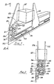
- Figure 1 is a perspective view of a short portion of the forwarding run of a conveyor in accordance with the invention having two chains;
- Figure 2 is a part-sectional view taken from the line II of Figure 1;
- Figure 3 is a diagrammatic section of another embodiment having two chains;
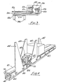
- Figure 4 corresponds to Figure 1 but shows an embodiment having three chains;
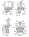
- Figures 5, 6 and 7 are diagrammatic sections of other embodiments having three chains;
- Figures 8, 9, 10 and 11 are diagrammatic sections of embodiments having two pairs of chains;
- Figure 12 is a diagrammatic side elevation showing how two conveyor chains, e.g., as in Figures 1 and 2 or at one side of any one of Figures 8, 9, 10 or 11, are trained round separate driving sprockets at one end of the conveyor and round a pair of guide blocks at the other end;
- Figures 13 and 14 are respective side elevations of the guide block for the inner chain in Figure 12;
- Figures 15 and 16 are respective side elevations of the guide block for the outer chain in Figure 12;
- Figure 17 is a vertical section, taken from the line XVII-XVII of Figure 18, showing the two guide blocks assembled together on a frame plate of a conveyor assembly;
- Figure 18 is an elevation from the left hand side of Figure 17 showing means of adjustment of the positions of the guide blocks for tensioning of the chains; and
- Figure 19 is a fragmentary view in the direction of arrow XIX in Figure 17 showing the initial positions of the guide blocks in relation to the elongate guide members.
- In Figures 1 and 2, two parallel
endless chains 20, 21 (see also Figure 12) carryflights 22, 23 (only one being shown on each chain respectively) and run along guide tracks consisting of an inner (or lower)guide track 24 for the chain 2Ø and an outer (or upper)guide track 25 for thechain 21, the guide tracks being disposed so that one chain overlaps the other in the direction transverse to the direction in which the flights project, and the flights projecting to the outer sides of both chains. - Thus a closer spacing of the
flights flights shallow containers 26 along supportingsurfaces 27 onrails 28. - The
guide tracks channels 29 in a singleelongate guide member 30, which may be formed of low-friction material, or (as shown in Figures 1 and 2)channels 29 in ametal member 30 may be provided with low-friction liners 31 contacting thechains elongate guide member 30 being secured to aframe member 32 by screws orbolts 33 having their heads accommodated inlongitudinal grooves 34. Also in Figures 1 and 2 the elongatemetal guide member 30 has a longitudinal T-shaped rib 35 on to which is fitted atop rail 36 of low-friction material for contactingcontainers 37 propelled therealong. - In Figures 4 to 7, three parallel
endless chains flights guide tracks guide track 48 is disposed inwardly of (or below) the other twoguide tracks guide track 46 in the direction transverse to the direction in which the flights project. - The diagrammatic Figure 5 has the same disposition of flights as in the detailed perspective Figure 4, i.e., the
flights 45 on thechain 42 in theinner guide track 48 extend between the other twoguide tracks flights chains guide track elongate guide member liners 31 contacting the chains), while in Figure 5 theguide tracks elongate guide member 52. - In Figure 6 the
flights chains tracks narrow article 37. Although theguide tracks elongate guide members guide tracks flights chains guide tracks other guide track 46, one beyond the other, and all three guide tracks are shown formed in a singleelongate guide member 53. - Another close disposition of flights is achievable with the embodiment of Figure 8 in which a conveyor comprises two pairs of parallel
endless chains 55B carrying flights guide tracks guide tracks guide track guide track elongate guide member - In Figure 9, the two assemblies of, on the one hand, the
elongate guide member 60A withguide tracks chains flights elongate guide member 60B withguide tracks chains 54B, 55B andflights - The embodiment of Figure 10 is similar in disposition to the embodiment of Figure 8, but the
tracks rails spacers 63 toframe members outer rail 62 of theinner track inner rail 61 of theouter track - It will be evident from a comparison with any of Figures 8, 9 and 10 with Figure 11 that "mirror image" assemblies of elongate guide members with guide tracks, chains and flights can be readily spaced apart to suit any width of article. However, it will be seen that the assemblies shown in Figure 11 differ from those of Figures 8 and 9 in that the tracks in each elongate guide member face or open to opposite sides; this renders possible a comparison of the left hand assembly in Figure 11 with the assembly of Figures 1 and 2, which is a preferred embodiment for use in a conveyor of packaging machinery having a "mirror image" assembly similarly secured to a frame member which is movable with respect to the frame member to adjust the spacing of assemblies, and the further description will include the same reference numerals as in Figures 1 and 2 where appropriate.
- The chains will require a similar disposition in a return run and are conveniently provided with similar guide tracks, similarly provided by channels in elongate guide members as described above, but with an inverted disposition of the pairs of channels, see Figures 17 and 19 in particular and which will now be described in conjunction with diagrammatic Figure 12 and Figures 13 to 16 and Figure 18 showing details of novel chain guiding and automatic tensioning means.
- It will be evident from Figure 12 that the outer pairs of
chains 21 extend further than the inner pairs ofchains 20 to drivingsprockets forward run 67. A similar arrangement could be provided for pairs of return sprockets, but ― in accordance with a further aspect of the invention ― a pair ofguide blocks 68, 69 (see Figures 13 to 19) are provided to guide thechains - The guide blocks 68, 69 are formed of low-friction material and have
semicircular track portions outer chains - The
inner guide block 68 has alongitudinal recess 74 with parallel sides for slidably engaging acomplementary projection 75 on one side of theouter guide block 69, the other side of which has a longer but lesser similar projection 76 for slidably engaging alongitudinal slot 77 in theframe member 32, and the assembly of guide blocks 68, 69 is held in place by aplate 78 overlapping the longitudinal edges of theslot 77 and bynuts 79 onbolts 80 through holes 81 in theinner guide member 68 andslots 82 in the outer guide member. - The guide blocks 68 and 69 have
parallel track portions semicircular portions inner guide block 68 abutssteps 85, 85X in theguide members steps outer guide block 69. Theliners 31 for the guide tracks 24, 25 (and 24R, 25R) have been omitted from Figure 19, as have also thechains flights - Figures 17 and 18 show a
clamp 90 secured to theinner guide block 68 by being bolted to theplate 78, and aclamp 91 bolted to theouter guide block 69, each clamp having an upwardly spring-loadedpawl 92 engaging aratchet bar 93, all being parts of the adjustment means 73, which also consists of anair cylinder 94 having apressure air inlet 95 and anexhaust outlet 96 with a filter, thepiston rod 97 of the air cylinder having apulley 98 round which passes awire cable 99 extending between theclamps semicircular guide 100. Theair cylinder 94 is pressurised periodically to pull on both guide blocks (through thewire cable 99 and clamps 90, 91) to tension thechains 20, 21 (if necessary), theratchet bar 93 andpawls 92 holding the tension so that theair cylinder 94 can be de-pressurised.
Claims (22)
Applications Claiming Priority (2)
| Application Number | Priority Date | Filing Date | Title |
|---|---|---|---|
| GB8807659 | 1988-03-31 | ||
| GB888807659A GB8807659D0 (en) | 1988-03-31 | 1988-03-31 | Conveyors |
Publications (2)
| Publication Number | Publication Date |
|---|---|
| EP0335738A1 EP0335738A1 (en) | 1989-10-04 |
| EP0335738B1 true EP0335738B1 (en) | 1991-12-18 |
Family
ID=10634408
Family Applications (1)
| Application Number | Title | Priority Date | Filing Date |
|---|---|---|---|
| EP89303211A Expired EP0335738B1 (en) | 1988-03-31 | 1989-03-31 | Conveyors |
Country Status (4)
| Country | Link |
|---|---|
| US (1) | US5038919A (en) |
| EP (1) | EP0335738B1 (en) |
| DE (1) | DE68900557D1 (en) |
| GB (1) | GB8807659D0 (en) |
Families Citing this family (27)
| Publication number | Priority date | Publication date | Assignee | Title |
|---|---|---|---|---|
| US4893707A (en) * | 1988-11-16 | 1990-01-16 | H. J. Langen & Sons Limited | Chain conveyors |
| GB9103962D0 (en) * | 1991-02-26 | 1991-04-10 | Cmb Foodcan Plc | An oven |
| DE4124943C2 (en) * | 1991-07-27 | 2002-06-27 | Klessmann Ima Norte Maschfab | A storage conveyor |
| DE4214886A1 (en) * | 1992-05-07 | 1993-11-11 | Automatisierungs Und Kunststof | Mechanism for feeding non-magnetic components individually to machines - uses parallel belts or chains which are provided with carrier elements |
| US5346050A (en) * | 1993-01-28 | 1994-09-13 | Fleetwood Systems, Inc. | Carton conveying apparatus |
| TR199501066A2 (en) * | 1994-08-30 | 1996-06-21 | Unilever Nv | Dry transportation system. |
| ATE181302T1 (en) * | 1995-10-27 | 1999-07-15 | Krups Kompaktlogistik Gmbh | METHOD AND DEVICE FOR EXTRACTING ROLLING PALLETS IN COMPACT STORAGE TECHNOLOGY, AND ROLLING PALLET THEREFOR |
| GB2317377B (en) * | 1996-09-09 | 2000-04-26 | Unilever Plc | Packaging Apparatus |
| US6279729B1 (en) | 1999-10-15 | 2001-08-28 | Goldco Industries, Inc. | Article conveyance having mechanical drive |
| ITBO20000685A1 (en) * | 2000-11-23 | 2002-05-23 | Gianluigi Gamberini | TOWING DEVICE FOR MACHINES FOR PACKAGING ARTICLES IN ROLLS AND SIMILAR |
| JP3567164B2 (en) * | 2001-02-09 | 2004-09-22 | バンドー化学株式会社 | Telescopic conveyor belt and method of manufacturing the same |
| US6550608B1 (en) * | 2001-11-02 | 2003-04-22 | Riverwood International Corporation | Carton feeding system for packaging machine |
| DE102004034570B3 (en) * | 2004-07-17 | 2005-06-30 | Cema Maschinenbau Gmbh | Feed conveyor for packaging machine has 2 transfer devices moved along feed path and return path via respective tension bands with independent drives |
| DE102004046733A1 (en) * | 2004-09-25 | 2006-04-06 | Rovema Verpackungsmaschinen Gmbh | Transport system for packages comprises pair of plates, between which package fits, which are mounted on front and rear rollers moved in guide rails by conveyor belt and connected by levers which pivot as the belt passes around end roller |
| DE102004046732A1 (en) * | 2004-09-25 | 2006-04-06 | Rovema Verpackungsmaschinen Gmbh | Transport system for filled packages comprises pair of plates, between which package fits, front plate having rollers at its base which move in grooves in H-profiled guide rail, rear plate having rollers which move in C-profile rails |
| ES2300733T3 (en) * | 2004-10-15 | 2008-06-16 | Kpl Packaging S.P.A. | DEVICE AND PROCEDURE TO AUTOMATICALLY CHANGE THE SIZE OF PACKAGES IN A CONVEYOR, IN PARTICULAR FOR AN AUTOMATIC PACKING MACHINE. |
| US7134544B1 (en) | 2005-07-28 | 2006-11-14 | Fki Logistex, Inc. | Conveyor belt system with take-up device |
| DE202005018076U1 (en) * | 2005-11-18 | 2007-03-29 | Seho Systemtechnik Gmbh | Support device of a transport device of a soldering machine |
| US7695421B2 (en) * | 2006-02-01 | 2010-04-13 | Graphic Packaging International, Inc. | Rotary carton feeder |
| US7752828B2 (en) * | 2008-06-19 | 2010-07-13 | Illinois Tool Works, Inc. | Loading apparatus and related method for loading edible items into trays |
| CH699295A2 (en) * | 2008-08-07 | 2010-02-15 | Soudronic Ag | Device and method for manufacturing lids with peel-off foil. |
| DE102008039036B4 (en) * | 2008-08-21 | 2011-07-14 | HARTING Applied Technologies GmbH & Co. KG, 32339 | Linear transport device |
| ES2544629T3 (en) * | 2010-09-15 | 2015-09-02 | Sigma Engineering B.V. | A device and method for packaging substantially flat products inside a box |
| US9073703B2 (en) | 2013-05-20 | 2015-07-07 | Laitram, L.L.C. | Apparatus and methods for dynamically controlling the spacing of conveyed objects |
| US9821961B2 (en) * | 2015-06-01 | 2017-11-21 | Illinois Tool Works Inc. | Adjustable conveying device |
| US10829250B2 (en) * | 2016-10-31 | 2020-11-10 | Westrock Shared Services, Llc | Methods and machine for packaging primary containers in secondary containers and a shipping tray |
| DE102017103917A1 (en) | 2017-02-24 | 2018-08-30 | Gerhard Schubert Gmbh | Supply chain unit |
Family Cites Families (12)
| Publication number | Priority date | Publication date | Assignee | Title |
|---|---|---|---|---|
| US1913001A (en) * | 1930-06-11 | 1933-06-06 | Crown Cork & Seal Co | Conveyer for bottle sealing and filling mechanism |
| US1989286A (en) * | 1932-07-30 | 1935-01-29 | Redington Co F B | Carton stripping and squaring mechanism |
| US2628542A (en) * | 1945-09-17 | 1953-02-17 | Emhart Mfg Co | Adjustable conveyer for cartoning machines |
| CH418956A (en) * | 1962-11-23 | 1966-08-15 | Kirsten Rolf | Machine for cartoning all kinds of filling goods |
| US3198316A (en) * | 1963-03-04 | 1965-08-03 | Bivans Corp | Sprocket drive for carton conveyor |
| BE758069A (en) * | 1969-10-28 | 1971-04-01 | Schlitz Brewing Co J | CARRIER |
| GB1351818A (en) * | 1970-06-19 | 1974-05-01 | Kammann W Kammann Werner | Transport device more especially for screen printing machines |
| US3825108A (en) * | 1972-09-05 | 1974-07-23 | Stone Conveyor Inc | Conveyor assembly with convertible extrusions |
| US4152960A (en) * | 1975-03-10 | 1979-05-08 | Mcdonough Manufacturing Company | Sawmill apparatus |
| SE431839B (en) * | 1979-05-29 | 1984-03-05 | Ackerfeldt Bo I | DEVICE FOR A CUTTING MACHINE OR A SIMILAR WORKING MACHINE FOR PROMOTING AND INPUTING THE WORK PIECE |
| JPS6052407A (en) * | 1983-09-01 | 1985-03-25 | Shibuya Mach Kk | Phase adjusting device for chain conveyor |
| US4768642A (en) * | 1987-06-16 | 1988-09-06 | Kimberly-Clark Corporation | Multiple conveyors with overlapping material handling device paths |
-
1988
- 1988-03-31 GB GB888807659A patent/GB8807659D0/en active Pending
-
1989
- 1989-03-31 EP EP89303211A patent/EP0335738B1/en not_active Expired
- 1989-03-31 US US07/332,350 patent/US5038919A/en not_active Expired - Lifetime
- 1989-03-31 DE DE8989303211T patent/DE68900557D1/en not_active Expired - Fee Related
Also Published As
| Publication number | Publication date |
|---|---|
| GB8807659D0 (en) | 1988-05-05 |
| EP0335738A1 (en) | 1989-10-04 |
| DE68900557D1 (en) | 1992-01-30 |
| US5038919A (en) | 1991-08-13 |
Similar Documents
| Publication | Publication Date | Title |
|---|---|---|
| US5038919A (en) | Conveyors with transversely spaced flights | |
| US4358010A (en) | Conveyor | |
| KR100264903B1 (en) | Chain propulsion belt conveyor | |
| US5156260A (en) | Conveyor construction having side rails with double longitudinal slots | |
| US4930623A (en) | Conveyor system and integral one-piece extended guidetrack | |
| KR930009154B1 (en) | Item sorting device with self-driven pallet | |
| US3857473A (en) | Powered rail conveyor | |
| EP0495245B1 (en) | Conveyor, in particular positioning conveyor | |
| EP1506125B1 (en) | Conveyor motor drive unit and conveyor system | |
| EP1326793B1 (en) | Device for transferring articles between oppositely running conveyors | |
| EP2609022B1 (en) | Positive displacement sorter | |
| GB1575327A (en) | Drive unit for an endless conveyor | |
| US4062444A (en) | Apparatus for cycleless transportation | |
| US6691856B1 (en) | Conveyor track of the smart-track type | |
| JP2004504235A (en) | Conveyor nose bar | |
| HU224157B1 (en) | Curved conveyor | |
| US3306430A (en) | Belt-chain combination drive | |
| CA2165048C (en) | Chain return support | |
| US20060070859A1 (en) | Conveyor system and method of using | |
| EP0608103B1 (en) | Packaging machine with flight bar carton conveying system | |
| US4890723A (en) | Plate type chip conveyor | |
| US20080035450A1 (en) | Slat driven positive displacement sorter | |
| US5244077A (en) | Transport gear chain arrangement | |
| GB2214479A (en) | Belt conveyor and pallets | |
| DK0930249T3 (en) | Transport device in a packing machine |
Legal Events
| Date | Code | Title | Description |
|---|---|---|---|
| PUAI | Public reference made under article 153(3) epc to a published international application that has entered the european phase |
Free format text: ORIGINAL CODE: 0009012 |
|
| AK | Designated contracting states |
Kind code of ref document: A1 Designated state(s): DE FR GB IT |
|
| 17P | Request for examination filed |
Effective date: 19890929 |
|
| 17Q | First examination report despatched |
Effective date: 19910328 |
|
| GRAA | (expected) grant |
Free format text: ORIGINAL CODE: 0009210 |
|
| AK | Designated contracting states |
Kind code of ref document: B1 Designated state(s): DE FR GB IT |
|
| REF | Corresponds to: |
Ref document number: 68900557 Country of ref document: DE Date of ref document: 19920130 |
|
| ET | Fr: translation filed | ||
| ITF | It: translation for a ep patent filed | ||
| PLBE | No opposition filed within time limit |
Free format text: ORIGINAL CODE: 0009261 |
|
| STAA | Information on the status of an ep patent application or granted ep patent |
Free format text: STATUS: NO OPPOSITION FILED WITHIN TIME LIMIT |
|
| 26N | No opposition filed | ||
| REG | Reference to a national code |
Ref country code: GB Ref legal event code: IF02 |
|
| PGFP | Annual fee paid to national office [announced via postgrant information from national office to epo] |
Ref country code: FR Payment date: 20050211 Year of fee payment: 17 |
|
| PGFP | Annual fee paid to national office [announced via postgrant information from national office to epo] |
Ref country code: IT Payment date: 20060331 Year of fee payment: 18 |
|
| REG | Reference to a national code |
Ref country code: FR Ref legal event code: ST Effective date: 20061130 |
|
| PGFP | Annual fee paid to national office [announced via postgrant information from national office to epo] |
Ref country code: DE Payment date: 20070226 Year of fee payment: 19 |
|
| PG25 | Lapsed in a contracting state [announced via postgrant information from national office to epo] |
Ref country code: FR Free format text: LAPSE BECAUSE OF NON-PAYMENT OF DUE FEES Effective date: 20060331 |
|
| PGFP | Annual fee paid to national office [announced via postgrant information from national office to epo] |
Ref country code: GB Payment date: 20080814 Year of fee payment: 20 |
|
| PG25 | Lapsed in a contracting state [announced via postgrant information from national office to epo] |
Ref country code: DE Free format text: LAPSE BECAUSE OF NON-PAYMENT OF DUE FEES Effective date: 20081001 |
|
| REG | Reference to a national code |
Ref country code: GB Ref legal event code: PE20 Expiry date: 20090330 |
|
| PG25 | Lapsed in a contracting state [announced via postgrant information from national office to epo] |
Ref country code: GB Free format text: LAPSE BECAUSE OF EXPIRATION OF PROTECTION Effective date: 20090330 |
|
| PG25 | Lapsed in a contracting state [announced via postgrant information from national office to epo] |
Ref country code: IT Free format text: LAPSE BECAUSE OF NON-PAYMENT OF DUE FEES Effective date: 20070331 |