JP3567164B2 - Telescopic conveyor belt and method of manufacturing the same - Google Patents
Telescopic conveyor belt and method of manufacturing the same Download PDFInfo
- Publication number
- JP3567164B2 JP3567164B2 JP2001398229A JP2001398229A JP3567164B2 JP 3567164 B2 JP3567164 B2 JP 3567164B2 JP 2001398229 A JP2001398229 A JP 2001398229A JP 2001398229 A JP2001398229 A JP 2001398229A JP 3567164 B2 JP3567164 B2 JP 3567164B2
- Authority
- JP
- Japan
- Prior art keywords
- belt
- width direction
- longitudinal direction
- hollow portion
- conveyor belt
- Prior art date
- Legal status (The legal status is an assumption and is not a legal conclusion. Google has not performed a legal analysis and makes no representation as to the accuracy of the status listed.)
- Expired - Fee Related
Links
Images


Classifications
-
- B—PERFORMING OPERATIONS; TRANSPORTING
- B29—WORKING OF PLASTICS; WORKING OF SUBSTANCES IN A PLASTIC STATE IN GENERAL
- B29D—PRODUCING PARTICULAR ARTICLES FROM PLASTICS OR FROM SUBSTANCES IN A PLASTIC STATE
- B29D29/00—Producing belts or bands
- B29D29/06—Conveyor belts
-
- B—PERFORMING OPERATIONS; TRANSPORTING
- B29—WORKING OF PLASTICS; WORKING OF SUBSTANCES IN A PLASTIC STATE IN GENERAL
- B29D—PRODUCING PARTICULAR ARTICLES FROM PLASTICS OR FROM SUBSTANCES IN A PLASTIC STATE
- B29D29/00—Producing belts or bands
- B29D29/08—Toothed driving belts
-
- B—PERFORMING OPERATIONS; TRANSPORTING
- B65—CONVEYING; PACKING; STORING; HANDLING THIN OR FILAMENTARY MATERIAL
- B65G—TRANSPORT OR STORAGE DEVICES, e.g. CONVEYORS FOR LOADING OR TIPPING, SHOP CONVEYOR SYSTEMS OR PNEUMATIC TUBE CONVEYORS
- B65G15/00—Conveyors having endless load-conveying surfaces, i.e. belts and like continuous members, to which tractive effort is transmitted by means other than endless driving elements of similar configuration
- B65G15/22—Conveyors having endless load-conveying surfaces, i.e. belts and like continuous members, to which tractive effort is transmitted by means other than endless driving elements of similar configuration comprising a series of co-operating units
- B65G15/26—Conveyors having endless load-conveying surfaces, i.e. belts and like continuous members, to which tractive effort is transmitted by means other than endless driving elements of similar configuration comprising a series of co-operating units extensible, e.g. telescopic
-
- B—PERFORMING OPERATIONS; TRANSPORTING
- B65—CONVEYING; PACKING; STORING; HANDLING THIN OR FILAMENTARY MATERIAL
- B65G—TRANSPORT OR STORAGE DEVICES, e.g. CONVEYORS FOR LOADING OR TIPPING, SHOP CONVEYOR SYSTEMS OR PNEUMATIC TUBE CONVEYORS
- B65G15/00—Conveyors having endless load-conveying surfaces, i.e. belts and like continuous members, to which tractive effort is transmitted by means other than endless driving elements of similar configuration
- B65G15/30—Belts or like endless load-carriers
- B65G15/32—Belts or like endless load-carriers made of rubber or plastics
- B65G15/34—Belts or like endless load-carriers made of rubber or plastics with reinforcing layers, e.g. of fabric
-
- B—PERFORMING OPERATIONS; TRANSPORTING
- B65—CONVEYING; PACKING; STORING; HANDLING THIN OR FILAMENTARY MATERIAL
- B65G—TRANSPORT OR STORAGE DEVICES, e.g. CONVEYORS FOR LOADING OR TIPPING, SHOP CONVEYOR SYSTEMS OR PNEUMATIC TUBE CONVEYORS
- B65G15/00—Conveyors having endless load-conveying surfaces, i.e. belts and like continuous members, to which tractive effort is transmitted by means other than endless driving elements of similar configuration
- B65G15/30—Belts or like endless load-carriers
- B65G15/32—Belts or like endless load-carriers made of rubber or plastics
- B65G15/42—Belts or like endless load-carriers made of rubber or plastics having ribs, ridges, or other surface projections
-
- B—PERFORMING OPERATIONS; TRANSPORTING
- B66—HOISTING; LIFTING; HAULING
- B66B—ELEVATORS; ESCALATORS OR MOVING WALKWAYS
- B66B23/00—Component parts of escalators or moving walkways
- B66B23/08—Carrying surfaces
- B66B23/10—Carrying belts
-
- B—PERFORMING OPERATIONS; TRANSPORTING
- B65—CONVEYING; PACKING; STORING; HANDLING THIN OR FILAMENTARY MATERIAL
- B65G—TRANSPORT OR STORAGE DEVICES, e.g. CONVEYORS FOR LOADING OR TIPPING, SHOP CONVEYOR SYSTEMS OR PNEUMATIC TUBE CONVEYORS
- B65G2201/00—Indexing codes relating to handling devices, e.g. conveyors, characterised by the type of product or load being conveyed or handled
- B65G2201/02—Articles
-
- Y—GENERAL TAGGING OF NEW TECHNOLOGICAL DEVELOPMENTS; GENERAL TAGGING OF CROSS-SECTIONAL TECHNOLOGIES SPANNING OVER SEVERAL SECTIONS OF THE IPC; TECHNICAL SUBJECTS COVERED BY FORMER USPC CROSS-REFERENCE ART COLLECTIONS [XRACs] AND DIGESTS
- Y10—TECHNICAL SUBJECTS COVERED BY FORMER USPC
- Y10S—TECHNICAL SUBJECTS COVERED BY FORMER USPC CROSS-REFERENCE ART COLLECTIONS [XRACs] AND DIGESTS
- Y10S428/00—Stock material or miscellaneous articles
- Y10S428/91—Product with molecular orientation
-
- Y—GENERAL TAGGING OF NEW TECHNOLOGICAL DEVELOPMENTS; GENERAL TAGGING OF CROSS-SECTIONAL TECHNOLOGIES SPANNING OVER SEVERAL SECTIONS OF THE IPC; TECHNICAL SUBJECTS COVERED BY FORMER USPC CROSS-REFERENCE ART COLLECTIONS [XRACs] AND DIGESTS
- Y10—TECHNICAL SUBJECTS COVERED BY FORMER USPC
- Y10T—TECHNICAL SUBJECTS COVERED BY FORMER US CLASSIFICATION
- Y10T428/00—Stock material or miscellaneous articles
- Y10T428/24—Structurally defined web or sheet [e.g., overall dimension, etc.]
- Y10T428/24479—Structurally defined web or sheet [e.g., overall dimension, etc.] including variation in thickness
- Y10T428/24521—Structurally defined web or sheet [e.g., overall dimension, etc.] including variation in thickness with component conforming to contour of nonplanar surface
- Y10T428/24529—Structurally defined web or sheet [e.g., overall dimension, etc.] including variation in thickness with component conforming to contour of nonplanar surface and conforming component on an opposite nonplanar surface
-
- Y—GENERAL TAGGING OF NEW TECHNOLOGICAL DEVELOPMENTS; GENERAL TAGGING OF CROSS-SECTIONAL TECHNOLOGIES SPANNING OVER SEVERAL SECTIONS OF THE IPC; TECHNICAL SUBJECTS COVERED BY FORMER USPC CROSS-REFERENCE ART COLLECTIONS [XRACs] AND DIGESTS
- Y10—TECHNICAL SUBJECTS COVERED BY FORMER USPC
- Y10T—TECHNICAL SUBJECTS COVERED BY FORMER US CLASSIFICATION
- Y10T428/00—Stock material or miscellaneous articles
- Y10T428/24—Structurally defined web or sheet [e.g., overall dimension, etc.]
- Y10T428/24628—Nonplanar uniform thickness material
-
- Y—GENERAL TAGGING OF NEW TECHNOLOGICAL DEVELOPMENTS; GENERAL TAGGING OF CROSS-SECTIONAL TECHNOLOGIES SPANNING OVER SEVERAL SECTIONS OF THE IPC; TECHNICAL SUBJECTS COVERED BY FORMER USPC CROSS-REFERENCE ART COLLECTIONS [XRACs] AND DIGESTS
- Y10—TECHNICAL SUBJECTS COVERED BY FORMER USPC
- Y10T—TECHNICAL SUBJECTS COVERED BY FORMER US CLASSIFICATION
- Y10T428/00—Stock material or miscellaneous articles
- Y10T428/24—Structurally defined web or sheet [e.g., overall dimension, etc.]
- Y10T428/24942—Structurally defined web or sheet [e.g., overall dimension, etc.] including components having same physical characteristic in differing degree
-
- Y—GENERAL TAGGING OF NEW TECHNOLOGICAL DEVELOPMENTS; GENERAL TAGGING OF CROSS-SECTIONAL TECHNOLOGIES SPANNING OVER SEVERAL SECTIONS OF THE IPC; TECHNICAL SUBJECTS COVERED BY FORMER USPC CROSS-REFERENCE ART COLLECTIONS [XRACs] AND DIGESTS
- Y10—TECHNICAL SUBJECTS COVERED BY FORMER USPC
- Y10T—TECHNICAL SUBJECTS COVERED BY FORMER US CLASSIFICATION
- Y10T428/00—Stock material or miscellaneous articles
- Y10T428/249921—Web or sheet containing structurally defined element or component
- Y10T428/249924—Noninterengaged fiber-containing paper-free web or sheet which is not of specified porosity
Abstract
Description
【0001】
【発明の属する技術分野】
この発明は伸縮式コンベヤベルト及びその製造方法に関し、特に人員搬送用として好適なコンベヤベルト及びその製造方法に関する。
【0002】
【従来の技術】
近年、高齢化社会への変化の中で各種建造物等においてバリヤフリー化の要請が高まっている。
例えば道路を横断する歩道橋においては、階段の昇り降りが高齢者にとってのバリヤとなっており、そこでその階段部分をバリヤフリー化すべく、曲走式の人員搬送用コンベヤベルトを、螺旋を描くように回曲した搬送路に沿って昇降移動させ、利用者を階段の昇り降りから解放するといったことが構想されている。
【0003】
或いはまた、近年におけるスピード化時代の中で人員の搬送をよりスピード化することが要望されており、その中にあって、可変速式の人員搬送用コンベヤベルトの実現が望まれている。
このような可変速式の人員搬送用コンベヤベルトを用いれば、乗り降りの際には支障を生じないようなゆっくりとしたスピードでコンベヤベルトを移動させる一方、そのような必要のない中間部分ではコンベヤベルトを速い速度で移動させ、これによって人員の搬送を高速化することが可能となる。
【0004】
【発明が解決しようとする課題】
しかしながら、従来のベルトは長手方向に抗張力を付与するために補強用の帆布やスチールコード等のベルト補強材が埋設されており、そのため長手方向に実質的に伸縮のできないものであって、これを上記の曲走式の人員搬送用コンベヤベルトとして、或いは可変速式の人員搬送用コンベヤベルトとしては用い得ないものであった。
【0005】
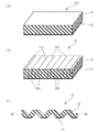
図26はこの種従来のベルトの例を示したものであって、この内(A)は、芯体帆布200をベルト補強材としてベルト内部に埋設した例を、また(B)はスチールコード202をベルト補強材としてベルト内部に埋設した例をそれぞれ示している。
尚、同図において204は上カバーゴムを、206は下カバーゴムを、208はクッションゴムを表している。
【0006】
曲走式の人員搬送用コンベヤベルトにあっては、曲りの内周側が長手方向に縮み、外周側が長手方向に伸びることが必要となるが、上記従来のベルトにあっては、ベルト補強材としての芯体帆布200ないしスチールコード202が何れも伸張状態でベルト内部に埋設されていて、ベルトを全幅に亘り長手方向に拘束しており、これがためベルトがカーブに沿って、即ち回曲した搬送路に沿って回曲運動することができないのである。
【0007】
また可変速式の人員搬送用コンベヤベルトにあっては、搬送路の中間部分でベルトが全幅に亘り長手方向に伸び、また人員の乗り降りする搬送路の端部ではベルトが全幅に亘り長手方向に縮むことが必要となるが、上記の理由によって従来のベルトの場合にはそのような動きをすることができず、かかる可変速式の人員搬送用コンベヤベルトとしても使用し得ないものである。
【0008】
以上人員搬送用コンベヤベルトについての問題点を述べたが、この問題はかかる人員搬送用コンベヤだけでなく、曲走式のコンベヤベルトや可変速式のコンベヤベルト一般に共通して生じる問題である。
そこでベルトを曲走式又は可変速式とするに際しては、ベルト幅方向の両側部分を長手方向に伸縮可能となしたり、或いはベルトを全幅に亘って長手方向に伸縮可能なものとなすことが必要となるが、如何にしてこれを実現するかが問題となる。
【0009】
【課題を解決するための手段】
本発明の伸縮式コンベヤベルト及びその製造方法はこのような課題を解決するために案出されたものである。
而して請求項1のものは伸縮式コンベヤベルトに関するもので、ベルトの厚み方向中間部にベルト幅方向に延びる空洞部が伸縮機能のための手段として設けてあり、且つ該空洞部の形状がベルト幅方向端に向って広がる形状となしてあることを特徴とする。
【0010】
請求項2のものは、ベルトの厚み方向中間部にベルト幅方向に延びる空洞部が伸縮機能 のための手段として設けてあるとともに、ベルト長手方向に延びる一対の可撓性の補強糸が前記空洞部を長手方向に交互に且つ互いに逆位相で回り込むように該長手方向に繰り返し湾・屈曲する形態でベルト内部に設けてあることを特徴とする。
【0011】
請求項3のものは、ベルト幅方向の両端部がローラにて支持されるコンベヤベルトであって、該幅方向の両端部にベルトの伸縮機能のための手段としての空洞部が厚さ方向の中間部に設けられるとともに、該空洞部の少なくとも下側に、ベルトに横剛性を付与するためのワイヤが層状に設けられていることを特徴とする。
【0012】
請求項4のものは、請求項3において、前記空洞部よりもベルト幅方向の中央部寄りの部分の裏面に、ベルト幅方向に延びる切欠きが伸縮機能のための手段としてベルト長手方向に所定間隔で設けられていることを特徴とする。
【0013】
請求項5のものは、請求項3,4の何れかにおいて、前記横剛性を付与するためのワイヤが、前記空洞部の下側と上側とに各層状に設けられていることを特徴とする。
【0014】
請求項6のものは、請求項3〜5の何れかにおいて、前記ワイヤの層がベルト幅方向において各端部に部分的に設けられているとともに、該各端部の空洞部と空洞部との間に、ベルトに対して横剛性を付与する、ベルト幅方向に延びる横剛性プレートがベルト長手方向に所定間隔で設けてあることを特徴とする。
【0015】
請求項7のものは、請求項3〜6の何れかにおいて、ベルト幅方向の中央部分に対しゴムの弾性に基づいて伸縮機能が付与されていることを特徴とする。
【0016】
請求項8は伸縮式コンベヤベルトの製造方法に関するもので、少なくともベルトの上側層又は下側層がベルト全幅に亘り一体成形されており且つ厚み方向中間部に、ベルト幅方向に延びる空洞部が伸縮機能のための手段としてベルト長手方向に所定間隔で設けられている伸縮式コンベヤベルトの製造方法であって、前記上側層と下側層とを別々に成形するとともにそれら上側層と下側層との下面及び上面のそれぞれに前記空洞部の一部を形成しておき、該上側層と下側層とを合せて固着することでベルトを構成するとともに、前記空洞部をベルトの厚み方向中間部に形成することを特徴とする。
【0017】
請求項9は伸縮式コンベヤベルトの製造方法に関するもので、少なくともベルトの上側層又は下側層がベルト全幅に亘り一体成形されており且つ厚み方向中間部に、ベルト幅方向に延びる空洞部が伸縮機能のための手段としてベルト長手方向に所定間隔で設けられている伸縮式コンベヤベルトの製造方法であって、前記空洞部に対応した形状の棒材を埋め込んだ状態でベルト成形し、その後該棒材を抜き取ることによって該空洞部を形成することを特徴とする。
【0018】
【作用及び発明の効果】
以上のように請求項1のものは、ベルトの厚み方向中間部の空洞部の形状をベルト幅方向端に向って広がる形状となしたもので、このようになした場合、その空洞部の形状に基づいてベルト長手方向の伸縮機能をベルト幅方向端に向って高めることができる。
この形態のコンベヤベルトは特に曲走式のコンベヤベルトとして好適であり、且つこの場合コンベヤベルトの曲りの曲率をより小さくすることができる。即ちより鋭いカーブに沿って大きく回曲運動させることができる。
但しその空洞部を実質的にベルト全幅に亘り設けておくなどして、これを可変速式のコンベヤベルトとして用いることも可能である。
【0019】
ここでベルト幅方向の両側部分にだけ長手方向の伸縮機能を持たせる場合及び実質的にベルト全幅に亘って長手方向の伸縮機能を持たせる場合の何れにおいても、ベルトの伸びを1.1倍以上となすことができる。
より望ましくは1.5倍以上、更に望ましくは1.8倍以上、更に望ましくは2倍以上、更に望ましくは2.5倍以上とすることができる。但し伸びの上限値については4倍としておくことができる。
【0020】
請求項2のものは、ベルト長手方向に延びる一対の可撓性の補強糸を、空洞部を長手方向に交互に且つ互いに逆位相で回り込むように、これを長手方向に繰り返し湾・屈曲する形態で設けたもので、この請求項2のコンベヤベルトにあっては、補強糸の作用によりベルトが一定の伸長度を超えて長手方向に過剰に伸長するのを阻止することができ、過剰な伸長によってベルトが損傷ないし破断するのを防止することができる。
【0021】
本発明においては、ローラにて支持されるベルト幅方向の両端部の下面に、ベルトの伸縮機能のための切込みや切欠き等を設けることも可能である。
しかしながらそのようにすると、その切込みや切欠きがローラを乗り越える際にベルトが急激に上下動振動を起したり衝撃が発生したりする不都合が生じる。
【0022】
そこで請求項3のコンベヤベルトにあっては、ローラにて支持されるコンベヤベルト幅方向の両端部に且つ厚み方向中間部に空洞部を伸縮機能のための手段として設け、そして少なくともその下側にベルトに横剛性を付与するためのワイヤを層状に設けたもので、このようになした場合、幅方向の両端部における長手方向の伸縮機能を大となしつつ、ベルトがローラを乗り越える際に急激な上下動振動を起したり衝撃を生じたりするのを防止でき、ベルトを円滑にローラ上を移動させることができる。
【0023】
また空洞部の下側にワイヤを層状に設けておくことで、空洞部の存在にも拘わらずローラによってベルト幅方向の両端部を良好に支持することができ、ひいてはコンベヤベルトによる荷重支持能力を高めることができる。
【0024】
請求項4のものは、上記空洞部よりもベルト幅方向の中央部寄りの位置の裏面に、ベルト幅方向に延びる切欠きを伸縮機能のための手段として長手方向に所定間隔で設けたもので、このようになしておくことにより、コンベヤベルトにおける幅方向の両側部分の伸縮機能をより高めることができる。
【0025】
請求項5のものは、横剛性を付与するためのワイヤを空洞部の下側と上側とに各層状に設けたもので、このようにすることでベルトの横剛性をより一層高め、荷重支持能力をより一層高めることができる。
【0026】
請求項6のものは、ワイヤの層をベルト幅方向の各端部に部分的に設けるとともに、一方の端部の空洞部と他方の端部の空洞部との間にベルトに対して横剛性を付与する、ベルト幅方向に延びる横剛性プレートをベルト長手方向に所定間隔で設けたもので、この横剛性プレートにより横方向の剛性をより一層高めることができる。
またベルト幅方向の両端部でローラによりベルトを支持するようになした場合であっても、ベルト幅方向の中央部分が下向きに垂れ下るのを良好に抑制することが可能となる。
【0027】
これらの場合において、ベルト幅方向の中央部分にゴム自身の弾性力による伸縮機能を付与しておくことができる(請求項7)。
このようになした場合、幅方向の中央部分における長手方向の伸縮機能に基づいて、ベルト幅方向の両側部分をより大きく伸長或いは収縮運動させることができるようになり、従って搬送路が比較的急激な曲り形状をなしている場合においてもベルトをこれに良く追従させることができるようになる。
或いはまたベルト幅方向の中央部分の伸縮機能によって、コンベヤベルトを可変速式のコンベヤベルトとして適用することも可能となる。更には場合によって曲走式且つ可変速式のコンベヤベルトとして使用することも可能となる。
【0028】
請求項8は伸縮式ベルトの製造方法に関するものである。
伸縮式ベルトの構成として、少なくともベルトの上側層又は下側層をベルト全幅に亘り一体成形し、且つベルトの厚み方向中間部において幅方向に延びる空洞部をベルト長手方向に所定間隔で設けた構成とすることができ、このようにすることでその空洞部によってベルト長手方向の伸縮機能を助長することができる。
そしてこのベルトは次のようにして製造することができる。
【0029】
即ちコンベヤベルトにおける上側層と下側層とを別々に成形するとともにその際に空洞部の一部をそれらに形成しておき、そしてそれら上側層と下側層とを合せて固着することでベルトを構成するとともに、空洞部をベルトの厚み方向中間部に形成することができる(請求項8)。
このようにすることで、厚み方向中間部に空洞部を有するベルトを容易に製造することができる。
【0030】
請求項9の製造方法は、上記空洞部に対応した形状の棒材を埋め込んだ状態でベルト成形し、その後棒材を抜き取ることによって空洞部を形成するもので、このようにした場合であっても厚み方向中間部に空洞部を有するベルトを容易に製造することができる。
尚、この請求項9に従い棒材を用いて空洞部を形成する場合、上側層と下側層とを含めて一体にベルト成形する場合においても、容易にベルトの厚み方向中間部に空洞部を形成することができる。
【0031】
【実施例】
次に本発明を人員搬送用コンベヤベルトに適用した場合の実施例を図面に基づいて詳しく説明する。
図1において、10は歩道橋における螺旋階段に代えて設置される曲走式の人員搬送装置で、曲走運動するコンベヤベルト12(以下単にベルトと略す)を有している。
ベルト12は、下位置の乗降箇所14Aから螺旋状の回曲運動をしつつ上昇して上位置の乗降箇所14Bへと到り、更に再び螺旋状の回曲運動をしつつ下降して下位置の乗降箇所14Aへと到る循環運動を行いながら、下位置の乗降箇所14Aから乗り移った人員を上位置の乗降箇所14Bへと搬送し、或いはまた上位置の乗降箇所14Bから乗り移った人員を下位置の乗降箇所14Aへと搬送する。
【0032】
即ち、ベルト12の裏面にはチェーンが固設されていて、そのチェーンに対しスプロケット18が噛み合い、そのスプロケット18の回転によりベルト12が駆動される。但しこれはあくまでチェーン駆動の一例である。
尚、同図において16はプーリである。
【0033】
図2はこの曲走式のベルトとして好適な一例を示したもので、図示のようにこのベルト12は、ゴム層20とその裏面に固着された帆布22とを有している。
この例のベルト12においては、長手方向に所定間隔で切込み24a,24bが交互に且つベルト12の全幅において設けられている。
【0034】
ここで切込み24aは、ベルト12の表面から裏面側に向って入れられており、また切込み24bは帆布22を貫通してベルト12の裏面から表面側に向って入れられている。
これら切込み24a,24bは、図2(B),(C)に示しているようにそれぞれベルト12の裏面又は表面に達しない非貫通のものである。
【0035】
帆布22は切込み24bによって長手方向に寸断されており、従って帆布22はベルト12に対する長手方向のベルト補強材を構成していない。
即ちこの例のベルト12は、ゴム層20の弾性力によって長手方向に伸びが確保されており、そして長手方向に沿って所定間隔ごとに設けられた切込み24a,24bによって、その長手方向の伸縮機能がベルト12全幅に亘って高められている。
【0036】
図2(C)はベルト12を長手方向に伸張させたときの状態を表している。
図示のようにベルト12は、切込み24a,24bの存在によって長手方向に大きく伸びることができる。
因みにこの例のベルト12は長手方向に約2.5倍の伸び(破断時の伸び)を有している。
【0037】
図示のようにこの例のベルト12は、切込み24a,24bが全幅に設けられることで、全幅に亘って長手方向の伸縮機能を有しており、且つ切込み24a,24bが長手方向に均等な間隔で設けられていることによって長手方向に均等な伸縮機能を有している。
従ってこの例のベルト12は曲走式のベルトとしては勿論、可変速式のベルトとしても特に好適に使用可能なものである。
【0038】
尚、同図(A)において12Aはベルト12に切込み24a,24bを入れる前の状態を表しており、この状態では帆布22は長手方向に連続した形態をなしている。
而してこのような帆布22を設けておくことによって、ベルト12Aを連続成形する際に、容易にこれを行うことができる。
【0039】
上記のように切込み24bを入れることによって帆布22は寸断された状態となり、使用状態の従来のベルトにおける帆布としての機能、即ちベルト補強材としての機能はその時点で失われる。
即ち基本的にこの例のベルト12はゴム層20のみによって人員搬送用のベルトとして必要な機能が実現されている。
【0040】
尚、この例のベルト12を用いて図1の人員搬送装置10を構成する場合には、ベルト12の裏面且つ幅方向の中央部にチェーンを取り付け、そのチェーンに対してスプロケット18を噛み合せてこれを駆動することとなる。
この点は以下の例においても同様である。
【0041】
この例のベルト12によれば、搬送路の曲りの部分においてその曲りの内周側の部分が長手方向に縮み、また外周側の部分が長手方向に伸びることができ、ベルト12全体をその回曲した搬送路に追従させつつ良好に曲走運動させることができる。
【0042】
またこの例では切込み24aと24bとをベルト12の長手方向に交互に設けているため、何れか一方の側からだけ切込み24a又は24bを設けた場合に比べて、ベルト12全体の長手方向の伸縮機能をより一層高めることができる。
【0043】
図3は他の例を示したもので、図示のようにこの例のベルト12は、ゴム層20の裏面に可撓性のベルト補強材としての芯体帆布28をベルト全幅に亘って固着して構成してある。
ゴム層20には、その裏面において全幅に亘り延びる切欠き26が長手方向に所定間隔で形成されており、それら切欠き26によって長手方向の伸縮機能が高められている。
【0044】
尚芯体帆布28はその切欠き26に沿ってゴム層20の裏面に固着されており、ベルト12が長手方向に伸張したときに同時にこれら芯体帆布28も切欠き26に沿った屈曲形状に基づいて、即ちその屈曲部分を長手方向に伸ばすようにして伸張する。
即ちこの例では、切欠き26によって長手方向の伸縮機能が高められるとともに、芯体帆布28が長手方向に繰り返し屈曲する形態で設けられていることによって、長手方向の伸縮機能が確保されている。
【0045】
尚この芯体帆布28は、ベルト12が長手方向に一定長さまで伸張されたときに同方向に伸び切った状態となり、以後ベルト12の更なる長手方向の伸びを阻止する。
即ち芯体帆布28は、ベルト12が一定以上長手方向に伸びるのを阻止するストッパとして働かせることもできる。
【0046】
この例のベルト12は、図3(B)に示しているように長手方向に沿って所定間隔で形成された突形部30を有する成形金型32を用いて容易に成形することができる。
この例のベルト12は、切欠き26を全幅に亘り長手方向に所定間隔で且つ芯体帆布28を全幅に亘って設けており、この例のベルト12もまた、全幅に亘って長手方向の伸縮機能を有し且つ長手方向に均等な伸縮機能を有している。
従ってこの例のベルト12もまた上記曲走用のベルトとして使用可能であることは勿論、可変速用のベルトとしても好適に使用可能なものである。
【0047】
図4は本発明の実施例を示したもので、この例では上側層及び下側層を合せた形態で一体成形したベルト12の厚み方向中間部に、即ちゴム層20の中間部に、伸縮機能のための手段として断面円形の空洞部34が全幅に亘って且つ長手方向に所定間隔で設けられており、それら空洞部34によってベルト12の長手方向の伸縮機能が高められている。
【0048】
この例ではまた、ゴム層20の内部に可撓性のベルト補強材としての補強糸(帆布糸)36が、空洞部34に沿って波打状に屈曲する形態で埋設されている。
ここで一方の補強糸36aと他方の補強糸36bとは、互いに逆位相をなすようにして且つ長手方向に一定間隔で設けてある空洞部34を交互に回り込むようにして、長手方向に繰り返し湾・屈曲する形態でゴム層20内部に埋設されている。
尚図中38はベルト12表面において長手方向に延びる突条で、幅方向に所定間隔ごとに且つ略全幅に亘り形成されている。
また40はベルト12の裏面に埋設された剛性のプレートである。
【0049】
本実施例のベルト12においても、空洞部34によって全幅に亘り且つ長手方向に均等に伸縮機能が高められており、更にまたゴム層20内部に埋設された補強糸36の屈曲形状に基づいて、長手方向の伸縮機能が確保されている。
この例において、補強糸36はベルト12が長手方向に一定長さまで伸張された時点で同方向に伸び切った状態となり、それ以上のベルト12の伸張を阻止するストッパとしても働く。これにより過剰な伸長によってベルト12が損傷ないし破断するのを防止することができる。
本例のベルト12もまた曲走用のベルトとして好適なのは勿論、可変速用のベルトとしても好適に使用可能なものである。
【0050】
尚この例の厚み方向中間部に空洞部34を有するベルト12は、図6に示しているように図5(B)に示す空洞部34に対応した形状の丸棒(棒材)42を所定間隔で配置して、それらに絡めるようにして補強糸36を設け、それらを挟み込むように上側層と下側層とを配置した状態でゴム層20を一体的に加硫成形してベルト12Aを得た後、丸棒42を抜き取ることで容易に製造することができる。
また上記補強糸36を用いることで、未加硫状態のベルトであっても、引込み用の帆布等を新たに用いることなく、ベルト本体を加硫工程へ引き込むことができるため、連続加硫が可能になる。
【0051】
尚上記空洞部34は他の種々形状で形成することが可能である。例えば図7の実施例に示しているように、断面四角形状の角棒(棒材)44を用いてベルト12を製造することにより、空洞部34の形状を断面四角形状となすこともできるし、或いはまた図8の実施例に示しているように断面楕円形状の楕円棒(棒材)46を用いて成形することにより、空洞部34を対応する断面楕円形状に形成することもできる。
更にはまた、図9の実施例に示しているように成形に際して六角棒(棒材)48を用いることで、空洞部34を対応する断面六角形状に形成することもでき、或いは他の多角形状その他形状にこれを形成することが可能である。
【0052】
図10は更に他の例を示している。
この例ではゴム層20内部(厚み方向中間部)にベルト補強材としての芯体帆布28を埋設するとともに、その芯体帆布28を長手方向波打状の湾曲形状となし、その湾曲形状に基づいてベルト12の長手方向の伸縮機能を確保するようになした例である。
【0053】
尚この例において芯体帆布28は、幅方向の両端の耳ゴム部20A(図14参照)を除いてベルト12の略全幅に亘り埋設されている。
【0054】
この例においても、芯体帆布28はベルト12の長手方向の伸びに伴って伸張し、その伸びが一定に達したところで同方向に伸び切った状態となって、ベルト12の更なる伸びを阻止するストッパとして働かせることもできる。
【0055】
この例のベルト12は、次のようにして製造することができる。
即ち、図10(A)に示しているように、多数の山形状の突形部50を有する成形型52を用いて、先ずベルト12における下側層12−2を芯体帆布28とともに加硫成形しておき、その後において(B)に示しているようにその下側層12−2に上側層12−1を加硫成形し、一体化することでベルト12を容易に製造することができる。
【0056】
図11は更に他の例を示したもので、図示のようにこの例のベルト12は、図3の例においてベルト表面に突条38を設けるとともに、裏面に金属,樹脂等から成る横剛性部材としての横剛性プレート54をベルト全幅に亘って且つ長手方向に所定間隔で固着し、それら横剛性プレート54によってベルト12に対し横剛性を付与した例である。
このベルト12においては、横剛性プレート54により、長手方向の伸縮機能を保持しつつ横方向の剛性を付与することができる。
【0057】
本例のベルト12では、横剛性プレート54がベルト12の全幅に亘って設けられているため、例えばベルト12を幅方向の両端部で後述のローラ70等により支持した場合であっても、その幅方向の中央部分が下向きに撓み、垂れ下るのを良好に抑制することができる。
またこのように横剛性プレート54を設けておくことによって、ベルト12の幅方向の収縮を防止することができる。
【0058】
尚この例では、図3の例のベルト12に対してその裏面に横剛性プレート54を設けているが、勿論その他の実施例のベルト12において、その裏面に横剛性プレート54を設けた形態となすことも可能である。
【0059】
尚図11の例では、芯体帆布28の外側に横剛性プレート54が設けてあるが、図12に示しているように横剛性プレート54を包み込むようにしてその外側に芯体帆布28を設けるようにしても良い。
このようにすることで、横剛性プレート54の加硫接着不良による落下を防止できる効果が得られる。
【0060】
尚この図12の例ではベルト12の全幅に亘って芯体帆布28を設けているが、図13に示しているように横剛性プレート54の幅方向の中央部分を下向きの突形状に形成してこれを外部に露出させる一方、幅方向の両側部分だけに芯体帆布28を設けるようにしても良い。
このようにすることで、ベルト12の幅方向の中央部分の裏面にベルト駆動用の部材を取り付けるに当ってこれを容易に行うことができる。
【0061】
図14は更に他の例を示したもので、この例のベルト12では、耳ゴム部20Aを除いて実質的にベルト12の全幅に亘って延びるワイヤ(横剛性部材)56を長手方向に実質上連続的(微小間隙を隔てている場合も含む)に且つ層状に設けて、そのワイヤ56によってベルト12に対し幅方向の剛性、即ち横剛性を付与するようになした例である。
【0062】
ここでワイヤ56の層は、ゴムを結合材として多数のワイヤ56を1枚のシート状に連結し、その状態でベルト12内部に埋設するようになすことができる。
このようになした場合、容易にベルト12内部にワイヤ56を層状に設けることができる。
【0063】
この例では、ワイヤ56の層を所定間隔を隔てて上下に2層に設けており、これによってベルト12の横剛性を効果的に高剛性化することができ、従って荷重支持能力をより一層高めることができる。
尚、ゴム層20の内部には図3の例と同様にベルト補強材としての芯体帆布28が、長手方向に繰り返し屈曲する形態で埋設されている。
【0064】
図15は更に他の例を示したもので、この例はベルト12におけるゴム層20の厚み方向中間部に且つ幅方向の中央部分にのみ芯体帆布28を長手方向に伸張状態で埋設し、幅方向の両側部分についてはこの芯体帆布28を非存在の状態、即ちゴム層20のみの形態でベルト12を構成したものである。
このベルト12にあっては、幅方向の中央部分については実質的に長手方向に伸縮機能が付与されておらず、両側部分だけがゴム層20の弾性によって長手方向に伸縮機能が付与されている。
従ってこの例のベルト12は、特に曲走用のベルトとして好適なものである。
【0065】
図16は本発明の実施例を示したもので、この例では上側層及び下側層ともに一体成形したベルト12の内部(厚み方向中間部)に、即ちゴム層20の内部に、幅方向の中央部から両端部に向って漸次広がる形態の空洞部34を設けた例である。
この例のベルト12の場合、空洞部34が幅方向の両端部に向って広がる形態をなしていることから、空洞部34の形状に基づいて長手方向の伸縮機能が幅方向端に向って高められ、幅方向の中央部分に対して両側部分が長手方向により大きな伸縮機能を有している。
【0066】
この例のベルト12は特に曲走式のベルトとして好適なものであるが、この例では幅方向の中央部分も長手方向に一定の伸縮機能を有しているため、可変速式のコンベヤベルトとして用いることもできる。
またこのベルト12では、曲りの曲率をより小さくすることができる。即ちより鋭いカーブに沿って大きく回曲運動させることができる。
【0067】
尚図16のベルト12における空洞部34を成形するに際しては、図17に示すようなテーパ形状の棒材58或いは60を用い、これを埋め込んだ状態でベルト12を一体に成形した後、それら棒材58,60を抜き取ることによって、空洞部34を容易に成形することができる。
【0068】
図18は図16の変形例を示したもので、この例ではベルト12の幅方向の中央部分については空洞部34を設けず、その両側部分にのみ空洞部34を設けた例である。
このようにした場合においても、幅方向の両側部分における長手方向の伸縮機能を中央部分のそれに対してより高めることができる。
【0069】
図19は更に他の例を示している。
この例は、図11の例においてベルト12の裏面の横剛性プレート54の裏面に、そのベルト12の駆動部材の一部をなすチェーン62を長手方向に連続的に固着した例である。
この例では、チェーン62がベルト12を幅方向の中央部分において長手方向に非伸縮状態に拘束するベルト補強材としての働きをなし、従ってこの例のベルト12は、幅方向の両側部分のみが長手方向に伸縮機能を有している。
従ってこの例のベルト12は、特に曲走用のベルトとして好適なものである。
【0070】
尚この例では図3の例のベルト12に対してその裏面に横剛性プレート54を設けてその裏面にチェーン62を固着しているが、勿論その他の例のベルト12において、その裏面にチェーン62を設けた形態となすことも可能である。
【0071】
次に図20〜図23は本発明の更に他の実施例を示している。
この例のベルト12は、ローラ70によって支持されるベルト幅方向の両端部にだけテーパ形状の空洞部34、詳しくは幅方向端に進むにつれ広がるテーパ形状の空洞部34を厚み方向中間部に設け、そしてその空洞部34の上側と下側とにベルト12の幅方向に延びる横剛性を付与するためのワイヤ56を、図22(イ)に示しているようにベルト12の長手方向に実質的に連続的(ここではワイヤ56と56との間に微小の間隙がある)に配置した形態で層状に設けてある。
【0072】
この例において、ワイヤ56の層は図22(イ)に示しているようにワイヤ56をゴム材で連結してシート72となし、そのシート72をベルト12の成形時に一体に積層することでベルト12に層状に設けてある。
【0073】
本例ではまた、幅方向各端部のワイヤ56と56との間の部分において、ベルト12の裏面にベルト12の幅方向に延びる横剛性プレート54が、それらワイヤ56の各端部と一部重複する状態で設けてある。
ここで横剛性プレート54は長手方向に一定間隔ごとに多数設けてある。
【0074】
図20,図21,図22(ウ)に示しているように、本例では空洞部34よりもベルト12の幅方向内側(中央部寄りの位置)において、所定ベルト幅方向長に亘ってベルト12の裏面に切欠き26がベルト長手方向に一定間隔ごとに設けてあり、更にそれら切欠き26を設けた部分において、芯体帆布28がベルト12の裏面及び切欠き26の内面に沿って長手方向に連続的に湾曲及び屈曲する形態で設けられている。
【0075】
そしてそれら図中左側の切欠き26及び芯体帆布28と右側の切欠き26及び芯体帆布28との間の部分、即ちベルト12の幅方向の中央部分において、ベルト12が横剛性プレート54を除いて基本的にゴム層20だけから成っている。
【0076】
本例においては、ローラ70にて支持されるベルト幅方向の両端部の下面に切込み24bや切欠き26等を設けず、空洞部34を厚み方向中間部に設けている。そしてその下側にワイヤ56を層状に設けていることから、ベルト幅方向の両端部における長手方向の伸縮機能を助長しつつ、ベルト12がローラ70を乗り越える際に急激な上下動振動を起したり衝撃を生じたりするのを防止でき、ベルト12を円滑にローラ70上を移動させることができる。
また空洞部34の下側にワイヤ56を層状に設けておくことで、空洞部56の存在にも拘わらずローラ70によってベルト12の幅方向の両端部を良好に支持することができ、ひいてはベルト12による荷重支持能力を高めることができる。
【0077】
また本例では空洞部34よりもベルト12の幅方向の中央部寄りの位置の裏面に、幅方向に延びる切欠き26を長手方向に一定間隔で設けていることから、ベルト幅方向の両側部分の伸縮機能をより高めることができる。
【0078】
またベルト幅方向の中央部分が横剛性プレート54を除いて基本的にゴム層20だけから成っているため、ゴム自身の弾性力によってその中央部分が長手方向に伸縮することができる。
【0079】
そして幅方向の中央部分における伸縮機能に基づいて、幅方向の両側部分の伸長或いは収縮能を高めることができ、従って搬送路が比較的急激な曲り形状をなしている場合においてもベルト12をこれに良く追従させることができる。
【0080】
次に図24は更に他の例を示している。
この例ではベルト12の厚み方向中間部に、ベルト12の幅方向に延びる空洞部34が長手方向に所定間隔ごとに設けられている。
尚この空洞部34はベルト12を幅方向に貫通する形態で設けておくこともできるし、両端部についてはこれを閉鎖した状態で設けておくこともできる。
【0081】
この例ではまた、ベルト12の厚み方向中間部においてベルト12の幅方向に延びる横剛性プレート54が、空洞部34と34との間の部分を繋ぐようにして長手方向に所定間隔ごとに且つ互いに重なる状態で2層積層状態で設けてある。
【0082】
この例のベルト12は、図25に示しているように上側の横剛性プレート54を含む上側層12−1と、下側の横剛性プレート54を含む下側層12−2とをそれぞれ別々に成形しておき、横剛性プレート(金具)54と54とを重ね合せるようにして上側層12−1と下側層12−2とを互いに固着し、一体のベルト12を構成している。
尚上側層12−1,下側層12−2はそれぞれベルト12の全幅に亘って一体に成形してある。
【0083】
ここで上側層12−1と下側層12−2とには、それぞれの下面と上面とに、上下に長い楕円形状をなす空洞部34の上半部34−1と下半部34−2とが予め成形されており、そして上側層12−1と下側層12−2とを重ね合せて固着し、一体のベルト12とすることで、厚み方向中間部に楕円形状の空洞部34を形成している。
【0084】
この場合において上側層12−1と下側層12−2とを固着する手段としては、金具から成る横剛性プレート54のベルト幅方向の端面に露出した部分を溶接接合したり、或いは横剛性プレート54と54とを接着固定したり、更にはまた図24(A)の部分拡大図に示しているように下側層12−2のゴムを一部除去してそこに穴74を設け、その穴74において上下の横剛性プレート54と54とをボルト76でねじ締結するなどの手段を用いることができる。
本例の製造方法によれば、厚み方向中間部に空洞部34を有するベルト12を容易に製造することができる。
【0085】
この例のベルト12もまた、ベルト幅方向の両端部の下面に凹凸が形成されておらず、従って図20のローラ70によってベルト幅方向の両端部を支持した場合において、ベルト12をそのローラ70上において円滑に走行させることができる。
【0086】
以上本発明の実施例を詳述したがこれらはあくまで一例示である。
例えば帆布にワイヤ等の横剛性部材を織り込んだ形態でベルト12に設けることも可能であるし、更に本発明を人員搬送用コンベヤベルト以外のコンベヤベルトに適用することも可能であるなど、本発明はその主旨を逸脱しない範囲において種々変更を加えた形態で構成可能である。
【図面の簡単な説明】
【図1】曲走用のベルトを用いた人員搬送装置の一例を模式的に表した図である。
【図2】ベルトの一例を示す図である。
【図3】ベルトの他の例を示す図である。
【図4】本発明の実施例のベルトを示す図である。
【図5】図4のベルトの要部及びその成形に用いる丸棒を示す図である。
【図6】図4のベルトにおける空洞部の成形方法の説明図である。
【図7】本発明の更に他の実施例のベルトを示す図である。
【図8】本発明の更に他の実施例のベルトを示す図である。
【図9】本発明の更に他の実施例のベルトを示す図である。
【図10】ベルトの更に他の例を示す図である。
【図11】ベルトの更に他の例を示す図である。
【図12】ベルトの更に他の例を示す図である。
【図13】ベルトの更に他の例を示す図である。
【図14】ベルトの更に他の例を示す図である。
【図15】ベルトの更に他の例を示す図である。
【図16】本発明の更に他の実施例のベルトを示す図である。
【図17】図16のベルトの空洞部を成形する棒材を示す図である。
【図18】本発明の更に他の実施例のべルトを示す図である。
【図19】ベルトの更に他の例を示す図である。
【図20】本発明の更に他の実施例のベルトを示す図である。
【図21】図20のベルトの要部拡大横断面図である。
【図22】図20のベルトの要部拡大縦断面図である。
【図23】図20のベルトの一部切欠断面図である。
【図24】ベルトの更に他の例を示す図である。
【図25】図24のベルトの製造方法の要部工程を示す図である。
【図26】従来用いられているベルトの一例を示す図である。
【符号の説明】
12 コンベヤベルト
12−1 上側層
12−2 下側層
20A 耳ゴム部
24a,24b 切込み
26 切欠き
28 芯体帆布(ベルト補強材)
34 空洞部
34−1 上半部
34−2 下半部
36,36a,36b 補強糸
42 丸棒(棒材)
44 角棒(棒材)
46 楕円棒(棒材)
48 六角棒(棒材)
54 横剛性プレート
56 ワイヤ(横剛性部材)
58,60 棒材
62 チェーン
70 ローラ[0001]
TECHNICAL FIELD OF THE INVENTION
The present invention relates to a telescopic conveyor belt and a method for manufacturing the same, and more particularly, to a conveyor belt suitable for transporting personnel and a method for manufacturing the same.
[0002]
[Prior art]
In recent years, with the change to an aging society, there is an increasing demand for barrier-free construction of various buildings and the like.
For example, on a pedestrian bridge that crosses roads, climbing up and down stairs is a barrier for elderly people.Therefore, in order to make the stairs barrier-free, a curving conveyer conveyor belt is drawn in a spiral. It is envisioned that the user is moved up and down along the curved transport path to release the user from going up and down stairs.
[0003]
Alternatively, in the era of speeding up in recent years, there has been a demand for speeding up the transfer of personnel, and among them, the realization of a variable-speed personnel transfer conveyor belt has been desired.
By using such a variable-speed conveyor belt for transporting personnel, the conveyor belt can be moved at such a slow speed that it does not cause a problem when getting on and off, while the conveyor belt is used at intermediate portions where such transfer is unnecessary. Can be moved at a high speed, thereby speeding up the transfer of personnel.
[0004]
[Problems to be solved by the invention]
However, in the conventional belt, a belt reinforcing material such as a canvas or a steel cord for reinforcement is buried in order to impart tensile strength in the longitudinal direction, so that it cannot substantially expand and contract in the longitudinal direction. It cannot be used as the above-mentioned curving-type personnel conveyor belt or as a variable-speed personnel conveyor belt.
[0005]
FIG. 26 shows an example of this type of conventional belt, in which (A) shows an example in which a
In the figure,
[0006]
In a curved type conveyor belt for personnel transport, it is necessary that the inner peripheral side of the bend contracts in the longitudinal direction and the outer peripheral side extends in the longitudinal direction, but in the above-mentioned conventional belt, as a belt reinforcing material Are embedded in the belt in an extended state, and the belt is restrained in the longitudinal direction over the entire width, so that the belt follows a curve, that is, a curved conveyance. They cannot turn around along the road.
[0007]
In the case of a variable-speed personnel conveyor belt, the belt extends in the longitudinal direction over the entire width at an intermediate portion of the transport path, and at the end of the transport path on which personnel enter and exits, the belt extends in the longitudinal direction over the entire width. Although it is necessary to shrink, the conventional belt cannot perform such movement for the above-mentioned reason, and cannot be used as such a variable-speed personnel conveyor belt.
[0008]
The problems with the conveyor belt for conveying personnel have been described above, but this problem is a problem that occurs not only in the conveyor for conveying personnel, but also in general in a curved conveyor belt or a variable speed conveyor belt.
Therefore, when making the belt a curved type or a variable speed type, it is necessary to make both sides in the belt width direction extendable in the longitudinal direction, or to make the belt extendable in the longitudinal direction over the entire width. However, how to achieve this is a problem.
[0009]
[Means for Solving the Problems]
The telescopic conveyor belt and the method of manufacturing the same according to the present invention have been devised to solve such problems.
ThusClaim1IsConcerning telescopic conveyor beltA hollow portion extending in the belt width direction is provided at an intermediate portion in the thickness direction of the belt as a means for the expansion and contraction function, and the shape of the hollow portion is shaped to expand toward the belt width direction end. And
[0010]
Claim2The onesA hollow part that extends in the belt width direction extends and contracts in the middle of the belt in the thickness direction. As a means forA pair of flexible reinforcing yarns extending in the longitudinal direction of the belt are provided inside the belt so as to be repeatedly bent and bent in the longitudinal direction so as to alternately wrap around the hollow portions in the longitudinal direction and in opposite phases to each other. It is characterized by.
[0011]
Claim3Is a conveyor belt in which both ends in the belt width direction are supported by rollers, and a hollow portion as a means for the elastic function of the belt is provided at both ends in the width direction at an intermediate portion in the thickness direction. In addition, a wire for imparting lateral rigidity to the belt is provided in a layer at least below the hollow portion.
[0012]
Claim4Is the claim3The notch extending in the belt width direction is provided at predetermined intervals in the belt longitudinal direction on the back surface of a portion closer to the central portion in the belt width direction than the hollow portion as a means for expanding and contracting function. I do.
[0013]
Claim5The onesThe wire according to any one of
[0014]
Claim6The onesThe belt according to any one of
[0015]
Claim7Is the claim3-6In any one of the above, a stretching function is provided to a central portion in the belt width direction based on elasticity of rubber.
[0016]
Claim8Is related to the method of manufacturing telescopic conveyor belt,At least the upper layer or the lower layer of the belt is integrally formed over the entire width of the belt, and cavities extending in the belt width direction are provided at predetermined intervals in the belt longitudinal direction as means for a stretching function at an intermediate portion in the thickness direction. ingA method of manufacturing a telescopic conveyor belt, wherein the upper layer and the lower layer are separately formed, and a part of the hollow portion is formed on each of the lower surface and the upper surface of the upper layer and the lower layer. The upper layer and the lower layer are fixed together to form a belt, and the hollow portion is formed at an intermediate portion in the thickness direction of the belt.
[0017]
Claim9Is related to the method of manufacturing telescopic conveyor belt,At least the upper layer or the lower layer of the belt is integrally formed over the entire width of the belt, and cavities extending in the belt width direction are provided at predetermined intervals in the belt longitudinal direction as means for a stretching function at an intermediate portion in the thickness direction. ingA method for manufacturing a telescopic conveyor belt, wherein a belt is formed in a state in which a bar having a shape corresponding to the cavity is embedded, and then the bar is removed to form the cavity.
[0018]
[Action and effect of the invention]
As aboveClaim1The shape of the hollow part in the middle part in the thickness direction of the belt is a shape that expands toward the end in the belt width direction.In such a case, based on the shape of the hollow part, the shape in the belt longitudinal direction is The stretching function can be enhanced toward the belt width direction end.
This type of conveyor belt is particularly suitable as a curved conveyor belt, and in this case, the curvature of the conveyor belt can be reduced. That is, it is possible to make a large turning motion along a sharper curve.
However, it is also possible to use this as a variable-speed conveyor belt, for example, by providing the hollow portion substantially over the entire width of the belt.
[0019]
Here, in both the case where the longitudinal stretching function is provided only on both side portions in the belt width direction and the case where the longitudinal stretching function is provided substantially over the entire width of the belt, the elongation of the belt is 1.1 times. The above can be achieved.
More preferably, it can be 1.5 times or more, further preferably 1.8 times or more, still more preferably 2 times or more, and still more preferably 2.5 times or more. However, the upper limit of the elongation can be set to four times.
[0020]
Claim2Is a pair of flexible reinforcing yarns extending in the longitudinal direction of the belt.,SkyThis is provided in the form of repeatedly bending and bending in the longitudinal direction so that the cavities alternately wrap around in the longitudinal direction and in opposite phases to each other.2In the conveyor belt of the above, the action of the reinforcing yarn can prevent the belt from being stretched excessively in the longitudinal direction beyond a certain degree of elongation, preventing the belt from being damaged or broken due to excessive elongation can do.
[0021]
In the present invention, it is also possible to provide a notch, a notch, or the like for the function of expanding and contracting the belt on the lower surface of both ends in the belt width direction supported by the roller.
However, in this case, when the notch or the notch crosses over the roller, there is a disadvantage that the belt suddenly generates vertical vibration and generates an impact.
[0022]
So the claim3In the case of the conveyor belt, the hollow portion is provided as a means for the expansion and contraction function at both ends in the width direction of the conveyor belt supported by the rollers and at the middle portion in the thickness direction, and at least a lateral rigidity is provided on the belt below the lower portion. In such a case, when the belt passes over the roller, the vertical vibration is increased when the belt expands and contracts in the longitudinal direction at both ends in the width direction. The belt can be prevented from causing a shock or causing an impact, and the belt can be smoothly moved on the roller.
[0023]
In addition, by providing wires in layers below the cavity, it is possible to favorably support both ends in the belt width direction with rollers despite the existence of the cavity, and consequently the load supporting capacity of the conveyor belt. Can be enhanced.
[0024]
Claim4Is provided with notches extending in the belt width direction at predetermined intervals in the longitudinal direction as means for the expansion and contraction function on the back surface at a position closer to the center in the belt width direction than the hollow portion. By doing so, the function of expanding and contracting both sides in the width direction of the conveyor belt can be further enhanced.
[0025]
According to a fifth aspect of the present invention, wires for imparting lateral rigidity are provided in layers on the lower side and the upper side of the hollow portion. In this manner, the lateral rigidity of the belt is further increased, and the load is supported. The ability can be further enhanced.
[0026]
According to a sixth aspect of the present invention, a layer of wire is partially provided at each end in the width direction of the belt, and a lateral rigidity with respect to the belt is formed between a cavity at one end and a cavity at the other end. The lateral rigid plates extending in the belt width direction are provided at predetermined intervals in the longitudinal direction of the belt, and the lateral rigidity can be further enhanced by the lateral rigid plates.
AlsoEven when the belt is supported by the rollers at both ends in the belt width direction, it is possible to satisfactorily prevent the central portion in the belt width direction from hanging down.
[0027]
ThisTheseIn the case of (1), an elastic function by the elastic force of the rubber itself can be provided to a central portion in the belt width direction.7).
In such a case, both sides in the belt width direction can be extended or contracted more and more based on the longitudinal expansion and contraction function in the central portion in the width direction. Even when the belt has a curved shape, the belt can follow the belt well.
Alternatively, the conveyor belt can be applied as a variable-speed conveyor belt by the expansion and contraction function of the central portion in the belt width direction. Further, in some cases, it can be used as a curving type and a variable speed type conveyor belt.
[0028]
Claim 8 relates to a method for manufacturing a telescopic belt.
As a configuration of the telescopic belt, at least an upper layer or a lower layer of the belt is integrally formed over the entire width of the belt, and hollow portions extending in the width direction at a middle portion in the thickness direction of the belt are provided at predetermined intervals in the belt longitudinal direction. In this manner, the hollow portion can promote the stretching function in the belt longitudinal direction.
This belt can be manufactured as follows.
[0029]
ImmediatelyThe upper layer and the lower layer of the conveyor belt are separately formed, and a part of the cavity is formed on the upper layer and the lower layer at that time, and the upper layer and the lower layer are bonded together and fixed. And the hollow portion can be formed at the intermediate portion in the thickness direction of the belt.8).
This makes it possible to easily manufacture a belt having a hollow part in the middle part in the thickness direction.
[0030]
Claim9Is a method of forming a belt by embedding a bar having a shape corresponding to the cavity, and then forming the cavity by extracting the bar, even in such a case, in the thickness direction. A belt having a hollow portion in the middle can be easily manufactured.
This claim9In the case where the hollow portion is formed by using the bar material according to the above, even when the belt is integrally formed including the upper layer and the lower layer, the hollow portion can be easily formed at the intermediate portion in the thickness direction of the belt.
[0031]
【Example】
Next, an embodiment in which the present invention is applied to a conveyor belt for transporting personnel will be described in detail with reference to the drawings.
In FIG. 1,
The
[0032]
That is, a chain is fixedly provided on the back surface of the
In the figure,
[0033]
FIG. 2 shows a preferred example of the curved belt. As shown, the
In the
[0034]
Here, the
These
[0035]
The
That is, in the
[0036]
FIG. 2C shows a state where the
As shown, the
Incidentally, the
[0037]
As shown in the figure, the
Therefore, the
[0038]
In FIG. 1A,
Thus, by providing such a
[0039]
By making the
That is, basically, in the
[0040]
In the case of using the
This point isExampleThe same applies to.
[0041]
thisAccording to the
[0042]
AlsothisIn the example, the
[0043]
FIG.Is another exampleAs shown in the figure, the
[0044]
The
That is, in this example, the
[0045]
When the
That is, the
[0046]
The
Therefore, the
[0047]
FIG. 4 shows the present invention.FruitIn this example, an intermediate portion in the thickness direction of the
[0048]
In this example, a reinforcing thread (canvas thread) 36 as a flexible belt reinforcing material is embedded in the
Here, the one reinforcing
In the drawing,
[0049]
This implementationAlso in the
In this example, when the
The
[0050]
As shown in FIG. 6, the
Further, by using the reinforcing
[0051]
The
Furthermore, FIG.Example ofBy using a hexagonal rod (bar material) 48 during molding, the
[0052]
FIG.IsTo othersExampleIs shown.
In this example, a
[0053]
In this example, the
[0054]
Also in this example, the
[0055]
The
That is, as shown in FIG. 10 (A), first, the lower layer 12-2 of the
[0056]
FIG.IsTo othersExampleAs shown, the
In the
[0057]
In the
Further, by providing the lateral
[0058]
In this example, FIG.ExampleThe lateral
[0059]
FIG. 11ExampleIn this embodiment, the lateral
By doing so, the effect of preventing the lateral
[0060]
FIG. 12ExampleIn FIG. 13, the
This makes it easy to attach the belt driving member to the back surface of the central portion in the width direction of the
[0061]
FIG.IsTo othersExampleIn the
[0062]
Here, the layer of the
In such a case, the
[0063]
thisIn the example, the layers of the
The inside of the
[0064]
FIG.IsTo othersExampleIn this example, the
In the
Therefore, the
[0065]
FIG. 16 shows the present invention.FruitIn this example, the upper layer and the lower layer are integrally formed inside the belt 12 (the middle part in the thickness direction), that is, inside the
In the case of the
[0066]
The
Further, in the
[0067]
In forming the
[0068]
FIG. 18 shows a modified example of FIG. 16. In this example, the
Also in this case, the longitudinal expansion and contraction function at both side portions in the width direction can be enhanced more than that of the central portion.
[0069]
FIG.IsTo othersExampleIs shown.
This example is shown in FIG.ExampleIn this example, a
In this example, the
Therefore, the
[0070]
In this example, FIG.ExampleA lateral
[0071]
Next, FIGS. 20 to 23 show still another embodiment of the present invention.
In the
[0072]
In this example, the layer of the
[0073]
In the present example, a lateral
Here, a large number of lateral
[0074]
As shown in FIG. 20, FIG. 21, and FIG. 22 (c), in this example, the
[0075]
In the portion between the
[0076]
In this example, the
Also, by providing the
[0077]
Further, in the present example, the
[0078]
In addition, since the central portion in the belt width direction is basically made of only the
[0079]
Based on the expansion and contraction function at the center portion in the width direction, it is possible to enhance the elongation or contraction ability of both side portions in the width direction. Therefore, even when the conveyance path has a relatively sharply curved shape, the
[0080]
Next, FIG.IsTo othersExampleIs shown.
In this example,
The
[0081]
Also in this example, a transverse
[0082]
As shown in FIG. 25, the
The upper layer 12-1 and the lower layer 12-2 are integrally formed over the entire width of the
[0083]
Here, the upper half part 34-1 and the lower half part 34-2 of the
[0084]
In this case, as a means for fixing the upper layer 12-1 and the lower layer 12-2, a portion of the lateral
According to the manufacturing method of this example, the
[0085]
The
[0086]
The embodiments of the present invention have been described above in detail, but these are merely examples.
For example, it is possible to provide the
[Brief description of the drawings]
FIG. 1 is a diagram schematically illustrating an example of a personnel conveying device using a curved belt.
FIG. 2BeRutoAn example ofFIG.
FIG. 3BeRutoOther examples ofFIG.
FIG. 4 shows the present invention.FruitIt is a figure showing a belt of an example.
FIG. 5 is a view showing a main part of the belt of FIG. 4 and a round bar used for molding the belt.
6 is an explanatory diagram of a method of forming a hollow portion in the belt of FIG.
FIG. 7 is a view showing a belt according to still another embodiment of the present invention.
FIG. 8 is a view showing a belt according to still another embodiment of the present invention.
FIG. 9 is a view showing a belt according to still another embodiment of the present invention.
FIG. 10BeRutoYet another example ofFIG.
FIG. 11BeRutoYet another example ofFIG.
FIG.BeRutoYet another example ofFIG.
FIG. 13BeRutoYet another example ofFIG.
FIG. 14BeRutoYet another example ofFIG.
FIG.BeRutoYet another example ofFIG.
FIG. 16 is a view showing a belt according to still another embodiment of the present invention.
FIG. 17 is a view showing a bar for forming a hollow portion of the belt of FIG. 16;
FIG. 18 is a view showing a belt according to still another embodiment of the present invention.
FIG.BeRutoYet another example ofFIG.
FIG. 20 is a view showing a belt according to still another embodiment of the present invention.
FIG. 21 is an enlarged cross-sectional view of a main part of the belt of FIG. 20;
FIG. 22 is an enlarged longitudinal sectional view of a main part of the belt of FIG. 20;
FIG. 23 is a partially cutaway sectional view of the belt of FIG. 20;
FIG. 24BeRutoYet another example ofFIG.
FIG. 25 is a diagram showing a main step of a method for manufacturing the belt in FIG. 24;
FIG. 26 is a diagram illustrating an example of a conventionally used belt.
[Explanation of symbols]
12 Conveyor belt
12-1 Upper layer
12-2 Lower layer
20A ear rubber part
24a, 24b notch
26 Notch
28 core canvas (belt reinforcement)
34 cavity
34-1 Upper half
34-2 Lower half
36, 36a, 36b Reinforcing yarn
42 round bar (bar material)
44 Square bar (bar material)
46 Elliptical bar (bar material)
48 Hex Bar (Bar)
54 Lateral rigid plate
56 wire (lateral rigid member)
58,60 bar
62 chain
70 rollers
Claims (9)
Priority Applications (6)
| Application Number | Priority Date | Filing Date | Title |
|---|---|---|---|
| JP2001398229A JP3567164B2 (en) | 2001-02-09 | 2001-12-27 | Telescopic conveyor belt and method of manufacturing the same |
| EP02002760A EP1231165B1 (en) | 2001-02-09 | 2002-02-07 | Stretchable conveyor belt and method of producing same |
| DE2002601763 DE60201763T2 (en) | 2001-02-09 | 2002-02-07 | Stretchable conveyor belt and method for its production |
| US10/067,547 US7060341B2 (en) | 2001-02-09 | 2002-02-07 | Stretchable conveyer belt and method of producing same |
| AT02002760T ATE281380T1 (en) | 2001-02-09 | 2002-02-07 | STRETCHABLE CONVEYOR BELT AND METHOD FOR PRODUCING SAME |
| HK03100791.8A HK1049649A1 (en) | 2001-02-09 | 2003-01-31 | Stretchable conveyor belt and method of producing same |
Applications Claiming Priority (3)
| Application Number | Priority Date | Filing Date | Title |
|---|---|---|---|
| JP2001-34550 | 2001-02-09 | ||
| JP2001034550 | 2001-02-09 | ||
| JP2001398229A JP3567164B2 (en) | 2001-02-09 | 2001-12-27 | Telescopic conveyor belt and method of manufacturing the same |
Publications (2)
| Publication Number | Publication Date |
|---|---|
| JP2002308560A JP2002308560A (en) | 2002-10-23 |
| JP3567164B2 true JP3567164B2 (en) | 2004-09-22 |
Family
ID=26609271
Family Applications (1)
| Application Number | Title | Priority Date | Filing Date |
|---|---|---|---|
| JP2001398229A Expired - Fee Related JP3567164B2 (en) | 2001-02-09 | 2001-12-27 | Telescopic conveyor belt and method of manufacturing the same |
Country Status (6)
| Country | Link |
|---|---|
| US (1) | US7060341B2 (en) |
| EP (1) | EP1231165B1 (en) |
| JP (1) | JP3567164B2 (en) |
| AT (1) | ATE281380T1 (en) |
| DE (1) | DE60201763T2 (en) |
| HK (1) | HK1049649A1 (en) |
Families Citing this family (10)
| Publication number | Priority date | Publication date | Assignee | Title |
|---|---|---|---|---|
| WO2005097657A1 (en) * | 2004-04-09 | 2005-10-20 | Toshiba Elevator Kabushiki Kaisha | Passenger conveyor |
| JP2008013351A (en) * | 2006-07-10 | 2008-01-24 | Ishikawajima Transport Machinery Co Ltd | Flexible belt |
| US20100025200A1 (en) * | 2006-11-13 | 2010-02-04 | Sergio Fandella | Hingeless belt |
| US8439184B2 (en) * | 2008-08-14 | 2013-05-14 | Arne Roy Jorgensen | High speed roofing shingle making machine including cutter, catcher and stacker |
| CA2714955C (en) * | 2009-10-09 | 2013-12-31 | Veyance Technologies, Inc. | Conveyor belt with varying flexibility and method of construction of same |
| US20120228092A1 (en) * | 2009-11-23 | 2012-09-13 | Erlbacher Ii Edwin A | Flexible track and system incorporating same |
| DE102011005397A1 (en) * | 2011-03-11 | 2012-09-13 | Krones Aktiengesellschaft | Mat for the transport of at least one article, transfer device and method of transfer |
| CA2750750A1 (en) * | 2011-08-29 | 2013-02-28 | James Haythornthwaite | Food transport belt |
| JP5915456B2 (en) * | 2012-08-23 | 2016-05-11 | 横浜ゴム株式会社 | Conveyor belt |
| CN108910413B (en) * | 2018-05-28 | 2020-04-28 | 四川大学 | Mineral transportation and manned integrated system |
Family Cites Families (17)
| Publication number | Priority date | Publication date | Assignee | Title |
|---|---|---|---|---|
| GB1105744A (en) | 1964-07-21 | 1968-03-13 | Dunlop Co Ltd | Improvements relating to belting |
| US3310161A (en) | 1965-03-31 | 1967-03-21 | Goodyear Tire & Rubber | Turn conveyor |
| US4085840A (en) | 1971-01-14 | 1978-04-25 | Torahiko Hayashi | Bakery flexible belt carrying plate |
| US3886149A (en) | 1972-06-01 | 1975-05-27 | Squibb & Sons Inc | Amino substituted dithiocarbonylthioacetyl cephalosporins |
| FI53685C (en) | 1976-06-24 | 1978-07-10 | Pohjola Jorma | LARVMATTA I ETT MED FASTSTAOENDE AENDRULLAR FOERSETT LARVFORDON |
| CH618138A5 (en) * | 1977-04-28 | 1980-07-15 | Habasit Ag | |
| CA1134770A (en) | 1978-09-21 | 1982-11-02 | Ralph W. Kell | Anti-backbend belts |
| JPS55109609A (en) | 1979-02-19 | 1980-08-23 | Utsuwa Kougei Yuugen | Prtparation of round vessel* whose fringe thickness differ* |
| IL72538A (en) * | 1984-07-30 | 1990-08-31 | Volta Power Belting Ltd | Method for splicing of elastomeric belts |
| US4769202A (en) * | 1985-11-29 | 1988-09-06 | The B. F. Goodrich Company | Process of making a conveyor belt |
| GB8807659D0 (en) * | 1988-03-31 | 1988-05-05 | Kliklok International Ltd | Conveyors |
| US5141101A (en) * | 1990-01-15 | 1992-08-25 | Jlv Industries Pty Ltd | Conveyor belt construction |
| DE4118137C1 (en) * | 1991-06-03 | 1992-06-04 | Promotex Werbetechnik Gmbh, 4030 Ratingen, De | Elastomeric imprinted advancing belt prodn. - comprises applying cut=outs to additional belt to form markings or writings, then fixing belt onto main belt |
| US5609242A (en) * | 1995-07-12 | 1997-03-11 | The Goodyear Tire & Rubber Company | Steel cable conveyor belt with improved penetration and rip resistance |
| JPH10139120A (en) | 1996-11-06 | 1998-05-26 | Yoshinao Yoshida | Conveyer belt capable of three-dimensional curved teaveling |
| JP2971412B2 (en) | 1997-03-07 | 1999-11-08 | バンドー化学株式会社 | Conveying belt with projection and method of manufacturing the same |
| JP2000169066A (en) | 1998-12-03 | 2000-06-20 | Ishikawajima Transport Machinery Co Ltd | Variable speed moving walk |
-
2001
- 2001-12-27 JP JP2001398229A patent/JP3567164B2/en not_active Expired - Fee Related
-
2002
- 2002-02-07 EP EP02002760A patent/EP1231165B1/en not_active Expired - Lifetime
- 2002-02-07 DE DE2002601763 patent/DE60201763T2/en not_active Expired - Fee Related
- 2002-02-07 US US10/067,547 patent/US7060341B2/en not_active Expired - Fee Related
- 2002-02-07 AT AT02002760T patent/ATE281380T1/en not_active IP Right Cessation
-
2003
- 2003-01-31 HK HK03100791.8A patent/HK1049649A1/en unknown
Also Published As
| Publication number | Publication date |
|---|---|
| HK1049649A1 (en) | 2003-05-23 |
| ATE281380T1 (en) | 2004-11-15 |
| EP1231165B1 (en) | 2004-11-03 |
| EP1231165A1 (en) | 2002-08-14 |
| US7060341B2 (en) | 2006-06-13 |
| JP2002308560A (en) | 2002-10-23 |
| DE60201763T2 (en) | 2005-10-27 |
| DE60201763D1 (en) | 2004-12-09 |
| US20020110676A1 (en) | 2002-08-15 |
Similar Documents
| Publication | Publication Date | Title |
|---|---|---|
| JP3567164B2 (en) | Telescopic conveyor belt and method of manufacturing the same | |
| JP3985870B2 (en) | Crawler belt, crawler device and crawler belt manufacturing method | |
| JP6858824B2 (en) | Small composite handrail with improved mechanical properties | |
| US20070199803A1 (en) | Method for making prestressed tubular belt | |
| FR2650857A1 (en) | DEVICE FOR PROMOTING THE FOLDING OF A LIFT CURTAIN | |
| JP2007520647A (en) | Squeezing belt | |
| JP3415837B2 (en) | Reinforced composite structure with spiral wound ribs | |
| ES2257411T3 (en) | BELT CVT REINFORCED REINFORCED. | |
| JP2002227937A (en) | Power transmission belt | |
| JPH05311621A (en) | Marking member | |
| CA1166990A (en) | Conveyor belt | |
| JP4343300B2 (en) | Man conveyor moving handrail and manufacturing method thereof | |
| US6161684A (en) | Herringbone conveyor belt | |
| WO1990003930A1 (en) | Improvements in tubular belt conveyors | |
| CN1079067C (en) | Linking-bar type rubber caterpillars and the core bars thereof | |
| CN220726994U (en) | Agricultural machinery V-belt for self-propelled combine harvester | |
| JPS5957878A (en) | Mobile handrail of curved passenger conveyor | |
| JP2001064953A (en) | Soil-sand removing and draining mat | |
| IT8323068A1 (en) | TRACK AND RELEVANT APPLICATION TO A VEHICLE | |
| JP2004238156A (en) | Conveyor belt and its manufacturing method | |
| KR102150043B1 (en) | foothold for floating structure and its manufacturing methode | |
| JPH0715674U (en) | Handrails for moving corridors | |
| ES2261169T3 (en) | WIRE WIRE FOR ELASTOMERO OR PLASTOMERO PROFILE AND ITS MANUFACTURING PROCEDURE. | |
| JPH04971Y2 (en) | ||
| JPS6258956B2 (en) |
Legal Events
| Date | Code | Title | Description |
|---|---|---|---|
| A01 | Written decision to grant a patent or to grant a registration (utility model) |
Free format text: JAPANESE INTERMEDIATE CODE: A01 Effective date: 20040309 |
|
| A61 | First payment of annual fees (during grant procedure) |
Free format text: JAPANESE INTERMEDIATE CODE: A61 Effective date: 20040316 |
|
| A711 | Notification of change in applicant |
Free format text: JAPANESE INTERMEDIATE CODE: A711 Effective date: 20040511 |
|
| A521 | Request for written amendment filed |
Free format text: JAPANESE INTERMEDIATE CODE: A821 Effective date: 20040511 |
|
| R150 | Certificate of patent or registration of utility model |
Free format text: JAPANESE INTERMEDIATE CODE: R150 |
|
| R250 | Receipt of annual fees |
Free format text: JAPANESE INTERMEDIATE CODE: R250 |
|
| FPAY | Renewal fee payment (event date is renewal date of database) |
Free format text: PAYMENT UNTIL: 20080625 Year of fee payment: 4 |
|
| FPAY | Renewal fee payment (event date is renewal date of database) |
Free format text: PAYMENT UNTIL: 20090625 Year of fee payment: 5 |
|
| LAPS | Cancellation because of no payment of annual fees |