EP0334972A1 - Electrical connector - Google Patents
Electrical connector Download PDFInfo
- Publication number
- EP0334972A1 EP0334972A1 EP88104898A EP88104898A EP0334972A1 EP 0334972 A1 EP0334972 A1 EP 0334972A1 EP 88104898 A EP88104898 A EP 88104898A EP 88104898 A EP88104898 A EP 88104898A EP 0334972 A1 EP0334972 A1 EP 0334972A1
- Authority
- EP
- European Patent Office
- Prior art keywords
- base part
- connector part
- connector
- electrical connector
- strut
- Prior art date
- Legal status (The legal status is an assumption and is not a legal conclusion. Google has not performed a legal analysis and makes no representation as to the accuracy of the status listed.)
- Granted
Links
Images
Classifications
-
- H—ELECTRICITY
- H01—ELECTRIC ELEMENTS
- H01R—ELECTRICALLY-CONDUCTIVE CONNECTIONS; STRUCTURAL ASSOCIATIONS OF A PLURALITY OF MUTUALLY-INSULATED ELECTRICAL CONNECTING ELEMENTS; COUPLING DEVICES; CURRENT COLLECTORS
- H01R13/00—Details of coupling devices of the kinds covered by groups H01R12/70 or H01R24/00 - H01R33/00
- H01R13/73—Means for mounting coupling parts to apparatus or structures, e.g. to a wall
- H01R13/74—Means for mounting coupling parts in openings of a panel
-
- H—ELECTRICITY
- H01—ELECTRIC ELEMENTS
- H01R—ELECTRICALLY-CONDUCTIVE CONNECTIONS; STRUCTURAL ASSOCIATIONS OF A PLURALITY OF MUTUALLY-INSULATED ELECTRICAL CONNECTING ELEMENTS; COUPLING DEVICES; CURRENT COLLECTORS
- H01R13/00—Details of coupling devices of the kinds covered by groups H01R12/70 or H01R24/00 - H01R33/00
- H01R13/62—Means for facilitating engagement or disengagement of coupling parts or for holding them in engagement
- H01R13/627—Snap or like fastening
Definitions
- the invention relates to an electrical connector consisting of a base part for installation in a housing wall and a connector part with a test adapter arranged thereon at the rear, which has screw angles for screwing to contact shoulders in the base part, and with latching elements on the base and connector part, which occur when the connector part is inserted from the inside facing away from the plug side snapping into the base part in the sense of a pre-fixing of the connector part on the base part.
- Known electrical connectors of this type enable, for many reasons, the introduction of the connector part together with the test adapter into the base part which was previously mounted on the outside of a base part previously mounted in the wall of a housing, for example a control cabinet, and indeed from the inside only by a single person, since it is possible for the installer to go from the inside due to the pre-fixation by the locking elements, after pre-fixation, for example, to go around the cabinet to the outside and then finally fix the connector part and the base part to screw together.
- the latching elements are formed, on the one hand, by wedge knobs provided on the two longitudinal inner walls of the base part and, on the other hand, by ribs arranged on the longitudinal sides of the connector part, which are snap-fitted when inserted from the inside over the wedge knobs.
- the present invention is therefore based on the object to provide an electrical connector of the generic type, in which the connector part can be easily disengaged from its prefixed position in the base part if necessary and without the use of tools.
- the solution according to the invention consists in the fact that the locking elements for the pre-fixing are formed by strut locking hooks arranged on the two narrow sides of the connector part as well as counter locking pieces provided on the base part.
- Such strut locking hooks form an easy-to-operate elastic system. If necessary, it is sufficient to press the spring strut hooks by hand in the sense of their unlocking in order to free the hooks from the counter-latching pieces. Due to their arrangement on the two narrow sides of the connector part, the suspension strut latch hooks are also extremely easy to reach overall and can therefore also serve as a whole for handling the connector part with an arranged test adapter.
- the existing protective contact angles on the side of the connector part can be taken in order to fasten the strut locking hooks thereon.
- the strut locking hooks are expediently formed in one piece with a mounting web, which in turn is designed to be clipped onto the corresponding protective contact angle.
- the electrical connector has a base part 1, which is fastened on the outer wall of a housing, for example a control cabinet, in the region of an opening through the wall, for which purpose it is provided with screw flanges 1a.
- the electrical connector further includes a connector part 2 with a test adapter 2a arranged thereon at the rear. As illustrated in FIG. 1, the connector part 2 with the test adapter 2a are inserted into the base part and fastened to the base part from the rear, ie from the inside facing away from the plug side.
- screw angles 3 are provided on the connector part 2, which can be screwed onto the shoulders 5 in the base part 1 by means of screws 4.
- a snap-in connection is provided between the base part 1 and the connector part 2 for a pre-fixation, which enables the person after inserting the connector part 2 into the base part 1 from the rear or inside to go to the front of the housing wall, for example of a control cabinet, in order to carry out the final screwing there.
- spring strut snap hooks 6 are now provided as a set of elements of the cooperating snap elements on the connector part 2 on its two narrow sides, for which counter locking pieces 7 are provided in the corresponding narrow sides of the inner wall area of the base part 1 are which are snapped behind by the hook sections at the lower free end of the strut locking hook 6 in the sense of pre-fixing.
- the strut locking hook 6 can be easily and conveniently pressed together by hand if necessary, i.e. H. to move towards the connector part 2, whereby the locking connection is released. Since the suspension strut hooks are particularly easy to reach due to their location on the two narrow sides of the connector part, they can also be used as a whole for handling the connector part. They are expediently provided on their outside with an ergonomically shaped recessed grip 8, which can be corrugated in the base in the sense of a secure grip.
- the protective contact angles 9 present on the narrow sides of the connector part 2 are used for the attachment and fixing of the strut locking hooks.
- the strut locking hooks 8 are formed in one piece with mounting webs 10, to which in turn clips 11 are integrally formed, which can be snapped onto a section of the protective contact angle 9, as shown in FIG. 3.
- a stop 12 is formed on the mounting webs 10, pointing outward toward the strut locking hook 8, which serves to protect the strut hook 8 against excessive compression.
Abstract
Description
Die Erfindung betrifft einen elektrischen Steckverbinder, bestehend aus einem Sockelteil für den Einbau in eine Gehäusewand und einem Verbinderteil mit rückwärtig daran angeordnetem Prüfadapter, das Schraubwinkel zur Verschraubung mit Anlageschultern im Sockelteil aufweist, sowie mit Rastelementen am Sockel- und Verbinderteil, die beim Einsetzen des Verbinderteiles von der der Steckseite abgewandten Innenseite her in das Sockelteil schnappend im Sinne einer Vorfixierung des Verbinderteiles am Sockelteil ineinandergreifen.The invention relates to an electrical connector consisting of a base part for installation in a housing wall and a connector part with a test adapter arranged thereon at the rear, which has screw angles for screwing to contact shoulders in the base part, and with latching elements on the base and connector part, which occur when the connector part is inserted from the inside facing away from the plug side snapping into the base part in the sense of a pre-fixing of the connector part on the base part.
Derartige bekannte elektrische Steckverbinder (DE-36 20 719 As) ermöglichen das aus vielen Gründen zu bevorzugende Einbringen des Verbinderteiles samt Prüfadapter in das zuvor auf die Außenseite eines zuvor in die Wand eines Gehäuses, beispielsweise eines Schaltschrankes, montierten Sockelteiles von innen her und zwar auch nur durch eine einzelne Person, da es bei diesem Einbringen von innen her aufgrund der Vorfixierung durch die Rastelemente für den Monteur möglich ist, nach Vorfixierung beispielsweise um den Schrank herum zu dessen Außenseite zu gehen, um von dort dann das Verbinderteil und das Sockelteil endgültig fest miteinander zu verschrauben.Known electrical connectors of this type (DE-36 20 719 As) enable, for many reasons, the introduction of the connector part together with the test adapter into the base part which was previously mounted on the outside of a base part previously mounted in the wall of a housing, for example a control cabinet, and indeed from the inside only by a single person, since it is possible for the installer to go from the inside due to the pre-fixation by the locking elements, after pre-fixation, for example, to go around the cabinet to the outside and then finally fix the connector part and the base part to screw together.
Bei dem bekannten elektrischen Steckverbinder sind die Rastelemente einerseits durch auf den beiden Längsinnenwänden des Sockelteiles vorgesehene Keilnoppen sowie andererseits durch auf den Längsseiten des Verbinderteiles angeordnete Rippen gebildet, die beim Einbringen von innen her schnappend über die Keilnoppen gepreßt werden.In the known electrical connector, the latching elements are formed, on the one hand, by wedge knobs provided on the two longitudinal inner walls of the base part and, on the other hand, by ribs arranged on the longitudinal sides of the connector part, which are snap-fitted when inserted from the inside over the wedge knobs.
Infolge dieser Ausgestaltung der Rastelemente für die Vorfixierung ist es nun aber praktisch nicht mehr oder nur mit großem Kraftaufwand unter Zerstörungsgefahr möglich, das Verbinderteil in einem Bedarfsfall, beispielsweise im Fall eines Irrtums, wieder aus dem Sockelteil herauszureißen.As a result of this configuration of the locking elements for the pre-fixation, it is now practically no longer possible or only with great effort and risk of destruction to tear the connector part out of the base part if necessary, for example in the event of an error.
Der vorliegenden Erfindung liegt von daher die Aufgabe zugrunde, einen elektrischen Steckverbinder der gattungsgemäßen Art zu schaffen, bei dem das Verbinderteil im Bedarfsfall leicht und ohne Zuhilfenahme von Werkzeugen aus seiner Vorfixierungslage im Sockelteil wieder ausgerastet werden kann.The present invention is therefore based on the object to provide an electrical connector of the generic type, in which the connector part can be easily disengaged from its prefixed position in the base part if necessary and without the use of tools.
Die erfindungsgemäße Lösung besteht darin, daß die Rastelemente für die Vorfixierung durch an den beiden Schmalseiten des Verbinderteiles angeordnete Federbeinrasthaken sowie entsprechend an dem Sockelteil vorgesehene Gegenraststücke gebildet sind.The solution according to the invention consists in the fact that the locking elements for the pre-fixing are formed by strut locking hooks arranged on the two narrow sides of the connector part as well as counter locking pieces provided on the base part.
Derartige Federbeinrasthaken bilden ein leicht zu betätigendes elastisches System. Es genügt im Bedarfsfall, von Hand auf die Federbeinrasthaken im Sinne ihrer Entriegelung zu drücken, um die Haken aus den Gegenraststücken frei zu bekommen. Die Federbeinrasthaken liegen dabei durch ihre Anordnung auf den beiden Schmalseiten des Verbinderteiles auch insgesamt äußerst griffgünstig und können daher auch für die Handhabung des Verbinderteiles mit angeordnetem Prüfadapter insgesamt dienen.Such strut locking hooks form an easy-to-operate elastic system. If necessary, it is sufficient to press the spring strut hooks by hand in the sense of their unlocking in order to free the hooks from the counter-latching pieces. Due to their arrangement on the two narrow sides of the connector part, the suspension strut latch hooks are also extremely easy to reach overall and can therefore also serve as a whole for handling the connector part with an arranged test adapter.
In weiterer zweckmäßiger Ausgestaltung können die vorhandenen seitlichen Schutzkontaktwinkel des Verbinderteiles genommen werden, um daran die Federbeinrasthaken zu befestigen. Dies führt zu einem denkbar einfachen konstruktiven Aufbau. Zweckmäßig sind in diesem Zusammenhang die Federbeinrasthaken einstückig mit einem Halterungssteg ausgebildet, der seinerseits auf den entsprechenden Schutzkontaktwinkel aufclipsbar ausgebildet ist.In a further expedient embodiment, the existing protective contact angles on the side of the connector part can be taken in order to fasten the strut locking hooks thereon. This leads to a very simple construction. In this context, the strut locking hooks are expediently formed in one piece with a mounting web, which in turn is designed to be clipped onto the corresponding protective contact angle.
Ein Ausführungsbeispiel eines elektrischen Steckverbinders gemäß der Erfindung wird nachstehend unter Bezugnahme auf die beigefügte Zeichnung beschrieben.An embodiment of an electrical connector according to the invention is described below with reference to the accompanying drawings.
Es zeigen
- Figur 1 einen elektrischen Steckverbinder gemäß der Erfindung mit sprengbildlicher Darstellung des Sockelteiles und des Verbinderteiles mit rückwärtig daran angeordnetem Prüfadapter,
Figur 2 eine Teilseitenansicht des Verbinderteiles,Figur 3 eine Schnittdarstellung gemäß Schnitt III-III derFigur 2 durch die Clipsverbindung zwischen dem Halterungssteg des Federbeinrasthakens und dem Schutzkontaktwinkel am Verbinderteil.
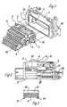
- 1 shows an electrical connector according to the invention with an exploded view of the base part and the connector part with a test adapter arranged on the rear,
- FIG. 2 shows a partial side view of the connector part,
- Figure 3 is a sectional view according to section III-III of Figure 2 by the clip connection between the bracket web of the strut latch and the protective contact angle on the connector part.
Der elektrische Steckverbinder hat ein Sockelteil 1, das auf der Außenwand eines Gehäuses, beispielsweise eines Schaltschrankes, im Bereich eines Durchbruches durch die Wand befestigt wird, wozu es mit Schraubflanschen la versehen ist. Der elektrische Steckverbinder beinhaltet ferner ein Verbinderteil 2 mit einem daran rückwärtig angeordneten Prüfadapter 2a. Das Verbinderteil 2 mit dem Prüfadapter 2a werden, wie in Figur 1 illustriert, bezogen auf die Gehäusewand von rückwärts, d.h. von der der Steckseite abgewandten Innenseite her, in das Sockelteil eingesetzt und daran befestigt. Für die definitive Befestigung von Verbinderteil 2 und Sockelteil 1 sind dazu an dem Verbinderteil 2 Schraubwinkel 3 vorgesehen, die mittels Schrauben 4 an Anlageschultern 5 im Sockelteil 1 angeschraubt werden können. Um diese Montagegänge von nur einer Person durchführen lassen zu können, ist zwischen dem Sockelteil 1 und dem Verbinderteil 2 eine Rastverbindung für eine Vorfixierung vorgesehen, die es der Person nach dem Einstecken des Verbinderteiles 2 in das Sockelteil 1 von rückwärts bzw. innen ermöglicht, auf die Vorderseite der Gehäusewand, beispielsweise eines Schaltschrankes, zu gehen, um dort die definitive Verschraubung durchzuführen. Um diese Vorfixierung im Bedarfsfall auch leichtgängig und ohne Werkzeug wieder lösen zu können, sind als ein Elementensatz der zusammenwirkenden Rastelemente nun an dem Verbinderteil 2 auf dessen beiden Schmalseiten Federbeinrasthaken 6 vorgesehen, für die in den entsprechenden schmalen Seiten des Innenwandbereiches des Sockelteiles 1 Gegenraststücke 7 vorgesehen sind, die von den Hakenabschnitten am unteren freien Ende der Federbeinrasthaken 6 federnd schnappend im Sinne der Vorfixierung hintergriffen werden.The electrical connector has a base part 1, which is fastened on the outer wall of a housing, for example a control cabinet, in the region of an opening through the wall, for which purpose it is provided with
Die Federbeinrasthaken 6 sind im Bedarfsfall problemlos und griffbequem von Hand zusammenzudrücken, d. h. in Richtung auf das Verbinderteil 2 zu zu bewegen, wodurch die Rastverbindung gelöst wird. Da die Federbeinrasthaken aufgrund ihrer Lage an den beiden Schmalseiten des Verbinderteiles insgesamt besonders griffgünstig liegen, können sie insgesamt auch zur Handhabung des Verbinderteiles als solchem benutzt werden. Sie sind zweckmäßig an ihrer Außenseite mit einer ergonomisch geformten Griffmulde 8 versehen, die im Sinne eines sicheren Greifens in ihrem Grund geriffelt sein kann.The
In zweckmäßiger, da konstruktiv einfacher Ausgestaltung werden die an den Schmalseiten des Verbinderteiles 2 vorhandenen Schutzkontaktwinkel 9 für die Anbringung und Festlegung der Federbeinrasthaken benutzt. Hierzu sind die Federbeinrasthaken 8 einstückig mit Halterungsstegen 10 geformt, an die ihrerseits abschnittsweise Clipse 11 angeformt sind, die schnappend über einen Abschnitt der Schutzkontaktwinkel 9 geclipst werden können, wie in Figur 3 gezeigt. Ferner ist an den Halterungsstegen 10, nach außen zum Federbeinrasthaken 8 weisend, ein Anschlag 12 angeformt, der dem Schutz des Federbeinrathakens 8 vor zu starken Zusammendrückung dient.In an expedient, structurally simple configuration, the
Claims (5)
Priority Applications (5)
| Application Number | Priority Date | Filing Date | Title |
|---|---|---|---|
| DE8888104898T DE3883209D1 (en) | 1988-03-26 | 1988-03-26 | ELECTRICAL CONNECTOR. |
| ES88104898T ES2043705T3 (en) | 1988-03-26 | 1988-03-26 | PLUGGABLE ELECTRICAL CONNECTOR. |
| EP88104898A EP0334972B1 (en) | 1988-03-26 | 1988-03-26 | Electrical connector |
| US07/327,091 US4940428A (en) | 1988-03-26 | 1989-03-22 | Electrical connector with resilient retaining means |
| CA000594725A CA1294680C (en) | 1988-03-26 | 1989-03-23 | Electrical plug and socket connector |
Applications Claiming Priority (1)
| Application Number | Priority Date | Filing Date | Title |
|---|---|---|---|
| EP88104898A EP0334972B1 (en) | 1988-03-26 | 1988-03-26 | Electrical connector |
Publications (2)
| Publication Number | Publication Date |
|---|---|
| EP0334972A1 true EP0334972A1 (en) | 1989-10-04 |
| EP0334972B1 EP0334972B1 (en) | 1993-08-11 |
Family
ID=8198843
Family Applications (1)
| Application Number | Title | Priority Date | Filing Date |
|---|---|---|---|
| EP88104898A Expired - Lifetime EP0334972B1 (en) | 1988-03-26 | 1988-03-26 | Electrical connector |
Country Status (5)
| Country | Link |
|---|---|
| US (1) | US4940428A (en) |
| EP (1) | EP0334972B1 (en) |
| CA (1) | CA1294680C (en) |
| DE (1) | DE3883209D1 (en) |
| ES (1) | ES2043705T3 (en) |
Cited By (2)
| Publication number | Priority date | Publication date | Assignee | Title |
|---|---|---|---|---|
| GB2281451A (en) * | 1993-08-13 | 1995-03-01 | Fujitsu Ltd | Electrical connecting arrangement for printed circuit boards detachably mounted in cabinet |
| CN110729592A (en) * | 2019-10-28 | 2020-01-24 | 易快(苏州)电气科技有限公司 | Take metal hasp structure and connector guard shield of barrier mechanism |
Families Citing this family (2)
| Publication number | Priority date | Publication date | Assignee | Title |
|---|---|---|---|---|
| US9083119B2 (en) * | 2013-03-14 | 2015-07-14 | Molex Incorporated | Connector having a housing with a pair of engagement arms and catch members |
| CN107658631A (en) * | 2017-10-31 | 2018-02-02 | 南京全信光电系统有限公司 | A kind of switching device for radar power supply protection |
Citations (3)
| Publication number | Priority date | Publication date | Assignee | Title |
|---|---|---|---|---|
| DE1765472A1 (en) * | 1967-05-24 | 1971-07-29 | Foxboro Co | Explosion-proof electrical plug connection |
| DE8308220U1 (en) * | 1983-03-19 | 1983-08-11 | Harting Elektronik Gmbh, 4992 Espelkamp | Electrical connector for installation in flange housing |
| DE3620719A1 (en) * | 1986-06-20 | 1987-12-23 | Wieland Elektrische Industrie | Electrical plug connector having a test adaptor |
Family Cites Families (6)
| Publication number | Priority date | Publication date | Assignee | Title |
|---|---|---|---|---|
| US4601527A (en) * | 1985-01-18 | 1986-07-22 | E. I. Du Pont De Nemours And Company | Shielded header and cable assembly |
| US4699438A (en) * | 1985-11-28 | 1987-10-13 | Hirose Electric Co., Ltd. | Locking mechanism for electrical connector |
| US4717359A (en) * | 1986-04-10 | 1988-01-05 | United Technologies Automotive, Inc. | Arrangement for securing electrical terminal in terminal holder |
| US4789346A (en) * | 1987-03-27 | 1988-12-06 | Amp Incorporated | Solder post alignment and retention system |
| US4718857A (en) * | 1987-04-10 | 1988-01-12 | Burndy Corporation | Electrical connectors and clips and methods of use |
| US4842529A (en) * | 1988-03-31 | 1989-06-27 | Amp Incorporated | Connector with two-piece ground strap |
-
1988
- 1988-03-26 DE DE8888104898T patent/DE3883209D1/en not_active Expired - Fee Related
- 1988-03-26 EP EP88104898A patent/EP0334972B1/en not_active Expired - Lifetime
- 1988-03-26 ES ES88104898T patent/ES2043705T3/en not_active Expired - Lifetime
-
1989
- 1989-03-22 US US07/327,091 patent/US4940428A/en not_active Expired - Lifetime
- 1989-03-23 CA CA000594725A patent/CA1294680C/en not_active Expired - Fee Related
Patent Citations (3)
| Publication number | Priority date | Publication date | Assignee | Title |
|---|---|---|---|---|
| DE1765472A1 (en) * | 1967-05-24 | 1971-07-29 | Foxboro Co | Explosion-proof electrical plug connection |
| DE8308220U1 (en) * | 1983-03-19 | 1983-08-11 | Harting Elektronik Gmbh, 4992 Espelkamp | Electrical connector for installation in flange housing |
| DE3620719A1 (en) * | 1986-06-20 | 1987-12-23 | Wieland Elektrische Industrie | Electrical plug connector having a test adaptor |
Cited By (4)
| Publication number | Priority date | Publication date | Assignee | Title |
|---|---|---|---|---|
| GB2281451A (en) * | 1993-08-13 | 1995-03-01 | Fujitsu Ltd | Electrical connecting arrangement for printed circuit boards detachably mounted in cabinet |
| US5513995A (en) * | 1993-08-13 | 1996-05-07 | Fujitsu Ltd. | Electrical connecting arrangement for establishment of electrical connections of electronic printed circuit boards detachably mounted in cabinet |
| GB2281451B (en) * | 1993-08-13 | 1997-12-17 | Fujitsu Ltd | Electrical connecting arrangement for establishment of electrical connections of electronic printed circuit boards detachably mounted in cabinet |
| CN110729592A (en) * | 2019-10-28 | 2020-01-24 | 易快(苏州)电气科技有限公司 | Take metal hasp structure and connector guard shield of barrier mechanism |
Also Published As
| Publication number | Publication date |
|---|---|
| DE3883209D1 (en) | 1993-09-16 |
| ES2043705T3 (en) | 1994-01-01 |
| CA1294680C (en) | 1992-01-21 |
| US4940428A (en) | 1990-07-10 |
| EP0334972B1 (en) | 1993-08-11 |
Similar Documents
| Publication | Publication Date | Title |
|---|---|---|
| DE2448137C2 (en) | Built-in box, in particular flush-mounted box | |
| DE1765266A1 (en) | On-off switch with snap fastening | |
| DE2523197C2 (en) | Device for the detachable attachment of electrical installation devices to mounting rails | |
| EP0300065B1 (en) | Mounting foot for the fixation of electrical or electronical components | |
| DE2901213C2 (en) | Detachable pin connection for components | |
| DE3432856C2 (en) | ||
| EP2858186B1 (en) | Busbar adapter | |
| EP0334972B1 (en) | Electrical connector | |
| EP0235350B1 (en) | Switch, in particular for a motor vehicle | |
| DE1575118C3 (en) | Screwless connector for electrical devices | |
| DE102018100360B4 (en) | rose furniture | |
| DE2355509C2 (en) | Assembly unit for electrical installation purposes | |
| DE19840642C2 (en) | Fastening element for an operating cable | |
| DE2310373C3 (en) | Wiper blade for windshield wiper systems for vehicles, in particular motor vehicles | |
| DE4031167C2 (en) | Electric lamp | |
| EP0562348B1 (en) | Device for fixing an elongated object to a base | |
| EP3618208A1 (en) | Cable tray and device for connecting cable trays | |
| DE2508484C3 (en) | Encapsulated electrical installation device | |
| DE2046344B2 (en) | Quick-action retaining mechanism - has plate with end hooks and locking spring to hold switch unit to support rail | |
| EP0003283A2 (en) | Mains socket to be mounted in an electrical appliance | |
| DE2648287A1 (en) | Coupling device for electric cables - with both ends having similar coupling elements with matching recesses, secured by clip when connected | |
| DE7602552U1 (en) | Electrical switching device | |
| DE2037268C3 (en) | Device box for electrical installation devices for installation in steel cell ceilings | |
| DE102020102427A1 (en) | Stray current bridge | |
| EP0394746B1 (en) | Locking device for an array of pins or sockets |
Legal Events
| Date | Code | Title | Description |
|---|---|---|---|
| PUAI | Public reference made under article 153(3) epc to a published international application that has entered the european phase |
Free format text: ORIGINAL CODE: 0009012 |
|
| AK | Designated contracting states |
Kind code of ref document: A1 Designated state(s): CH DE ES FR GB IT LI |
|
| 17P | Request for examination filed |
Effective date: 19891021 |
|
| 17Q | First examination report despatched |
Effective date: 19920109 |
|
| RAP1 | Party data changed (applicant data changed or rights of an application transferred) |
Owner name: WEIDMUELLER INTERFACE GMBH & CO. |
|
| ITF | It: translation for a ep patent filed |
Owner name: STUDIO INGG. FISCHETTI & WEBER |
|
| GRAA | (expected) grant |
Free format text: ORIGINAL CODE: 0009210 |
|
| AK | Designated contracting states |
Kind code of ref document: B1 Designated state(s): CH DE ES FR GB IT LI |
|
| GBT | Gb: translation of ep patent filed (gb section 77(6)(a)/1977) |
Effective date: 19930812 |
|
| REF | Corresponds to: |
Ref document number: 3883209 Country of ref document: DE Date of ref document: 19930916 |
|
| ET | Fr: translation filed | ||
| REG | Reference to a national code |
Ref country code: ES Ref legal event code: FG2A Ref document number: 2043705 Country of ref document: ES Kind code of ref document: T3 |
|
| PLBE | No opposition filed within time limit |
Free format text: ORIGINAL CODE: 0009261 |
|
| STAA | Information on the status of an ep patent application or granted ep patent |
Free format text: STATUS: NO OPPOSITION FILED WITHIN TIME LIMIT |
|
| 26N | No opposition filed | ||
| REG | Reference to a national code |
Ref country code: CH Ref legal event code: PL |
|
| REG | Reference to a national code |
Ref country code: CH Ref legal event code: AEN Free format text: WIEDEREINSETZUNG GUTGEHEISSEN |
|
| REG | Reference to a national code |
Ref country code: GB Ref legal event code: IF02 |
|
| PGFP | Annual fee paid to national office [announced via postgrant information from national office to epo] |
Ref country code: GB Payment date: 20030326 Year of fee payment: 16 |
|
| PGFP | Annual fee paid to national office [announced via postgrant information from national office to epo] |
Ref country code: CH Payment date: 20040302 Year of fee payment: 17 |
|
| PGFP | Annual fee paid to national office [announced via postgrant information from national office to epo] |
Ref country code: DE Payment date: 20040305 Year of fee payment: 17 |
|
| PGFP | Annual fee paid to national office [announced via postgrant information from national office to epo] |
Ref country code: FR Payment date: 20040310 Year of fee payment: 17 |
|
| PGFP | Annual fee paid to national office [announced via postgrant information from national office to epo] |
Ref country code: ES Payment date: 20040319 Year of fee payment: 17 |
|
| PG25 | Lapsed in a contracting state [announced via postgrant information from national office to epo] |
Ref country code: GB Free format text: LAPSE BECAUSE OF NON-PAYMENT OF DUE FEES Effective date: 20040326 |
|
| GBPC | Gb: european patent ceased through non-payment of renewal fee |
Effective date: 20040326 |
|
| PG25 | Lapsed in a contracting state [announced via postgrant information from national office to epo] |
Ref country code: IT Free format text: LAPSE BECAUSE OF NON-PAYMENT OF DUE FEES Effective date: 20050326 |
|
| PG25 | Lapsed in a contracting state [announced via postgrant information from national office to epo] |
Ref country code: ES Free format text: LAPSE BECAUSE OF NON-PAYMENT OF DUE FEES Effective date: 20050328 |
|
| PG25 | Lapsed in a contracting state [announced via postgrant information from national office to epo] |
Ref country code: LI Free format text: LAPSE BECAUSE OF NON-PAYMENT OF DUE FEES Effective date: 20050331 Ref country code: CH Free format text: LAPSE BECAUSE OF NON-PAYMENT OF DUE FEES Effective date: 20050331 |
|
| PG25 | Lapsed in a contracting state [announced via postgrant information from national office to epo] |
Ref country code: DE Free format text: LAPSE BECAUSE OF NON-PAYMENT OF DUE FEES Effective date: 20051001 |
|
| REG | Reference to a national code |
Ref country code: CH Ref legal event code: PL |
|
| PG25 | Lapsed in a contracting state [announced via postgrant information from national office to epo] |
Ref country code: FR Free format text: LAPSE BECAUSE OF NON-PAYMENT OF DUE FEES Effective date: 20051130 |
|
| REG | Reference to a national code |
Ref country code: FR Ref legal event code: ST Effective date: 20051130 |
|
| REG | Reference to a national code |
Ref country code: ES Ref legal event code: FD2A Effective date: 20050328 |