EP0334850B1 - Insulation for storage unit - Google Patents
Insulation for storage unit Download PDFInfo
- Publication number
- EP0334850B1 EP0334850B1 EP87907087A EP87907087A EP0334850B1 EP 0334850 B1 EP0334850 B1 EP 0334850B1 EP 87907087 A EP87907087 A EP 87907087A EP 87907087 A EP87907087 A EP 87907087A EP 0334850 B1 EP0334850 B1 EP 0334850B1
- Authority
- EP
- European Patent Office
- Prior art keywords
- insulation according
- longitudinal
- storage container
- plates
- panels
- Prior art date
- Legal status (The legal status is an assumption and is not a legal conclusion. Google has not performed a legal analysis and makes no representation as to the accuracy of the status listed.)
- Expired - Lifetime
Links
Images


Classifications
-
- F—MECHANICAL ENGINEERING; LIGHTING; HEATING; WEAPONS; BLASTING
- F16—ENGINEERING ELEMENTS AND UNITS; GENERAL MEASURES FOR PRODUCING AND MAINTAINING EFFECTIVE FUNCTIONING OF MACHINES OR INSTALLATIONS; THERMAL INSULATION IN GENERAL
- F16L—PIPES; JOINTS OR FITTINGS FOR PIPES; SUPPORTS FOR PIPES, CABLES OR PROTECTIVE TUBING; MEANS FOR THERMAL INSULATION IN GENERAL
- F16L59/00—Thermal insulation in general
- F16L59/12—Arrangements for supporting insulation from the wall or body insulated, e.g. by means of spacers between pipe and heat-insulating material; Arrangements specially adapted for supporting insulated bodies
-
- B—PERFORMING OPERATIONS; TRANSPORTING
- B65—CONVEYING; PACKING; STORING; HANDLING THIN OR FILAMENTARY MATERIAL
- B65D—CONTAINERS FOR STORAGE OR TRANSPORT OF ARTICLES OR MATERIALS, e.g. BAGS, BARRELS, BOTTLES, BOXES, CANS, CARTONS, CRATES, DRUMS, JARS, TANKS, HOPPERS, FORWARDING CONTAINERS; ACCESSORIES, CLOSURES, OR FITTINGS THEREFOR; PACKAGING ELEMENTS; PACKAGES
- B65D90/00—Component parts, details or accessories for large containers
- B65D90/02—Wall construction
- B65D90/06—Coverings, e.g. for insulating purposes
Definitions
- the invention relates to an insulation for storage containers as described in the preamble of claim 1.
- a known storage container with insulation - according to EP-A-117 338 - consists of preformed plate-shaped insulating bodies made of rigid foam plastic. In some areas, they are placed against these and connected to one another via profiled parts. These profiled parts have an arcuate profile in plan, each plate being provided with a groove on one side edge and with a connecting projection on the opposite side edge.
- circumferential tensioning straps were arranged outside the cover layer, as is known, for example, from US-A-163,347.
- these straps located outside of the insulation required additional material and considerable labor for assembly.
- the plates provided with such cover layers can only be used for storage containers of approximately the same diameter or for rectangular storage containers, since the corrugations of the cover layer of the adjacent plates would no longer be congruent with each other even with a small angular position of the adjacent plates , but would rather be tilted against each other. However, this would result in a force acting in the direction of lifting the plates from the storage container when connecting adjacent plates via connecting elements, or the connecting elements would be subjected to shearing. If one wanted to avoid this, the ends of the cover layers of the adjacent plates would have to be folded perpendicularly to the plate surface immediately before assembly to an extent adapted to the respective diameter of the storage container to be clad, in order to allow the overlapping parts of the cover layers to lie one inside the other.
- the invention has for its object to provide insulation that is able to withstand good wind insulation in addition to good thermal insulation due to the high suction forces in large outdoor stores.
- an embodiment according to claim 9 is also advantageous, since it is possible to find length with a single transverse tendon over the circumference of the storage container and the weight can be saved by a large number of coupling devices distributed over the circumference of the storage container.
- the adjacent transverse tendons can each be fastened in the central region of a plate arranged between them.
- this also opens up the possibility of providing a transverse tendon not only in the end regions but also in the longitudinal center of the panels.
- a further development according to claim 14 is advantageous. As a result, cutouts in the individual plates and thus zones with a reduced cross section can be avoided. In addition, compared to an embodiment according to which recesses are provided in the plates, the plates can be formed with a smaller wall thickness.
- the insulation can also be developed according to claim 15, whereby the cross or longitudinal tendons can be connected to such transverse tendons at any time.
- step-by-step tensioning of the cross-tendons already stiffens the individual panels during the construction of the insulation, making their assembly easier.
- possible displacements of the plates during tensioning can be prevented when tensioning the tendon due to the large tensioning paths.
- Each plate is thus supported on two areas spaced apart from one another in the circumferential direction of the container on the wall of the storage container, and vibrations that are harmful to the insulation can be damped more easily in this way.
- an embodiment according to claim 25 is also advantageous, since the penetration of moisture through joints or gaps is reliably prevented even at high wind pressures.
- a further embodiment of the insulation is provided in claim 26, whereby the formation of moisture and condensation between the outside of the storage container and the inside of the insulation is reliably prevented.
- an embodiment according to claim 27 is also advantageous, since in addition to the exact connection of the individual plates through the use of prefabricated profiles, a considerable stiffening of the plates in the region of the side edges is achieved, which can be found both during transport and during assembly and in association with the Isolation is characterized by a higher resistance to deformation under suction and pressure forces.
- a design according to claim 28 is also advantageous, since an intimate connection between the profiles and the foam plastic body of the plates is thereby achieved.
- a further development according to claim 31 is also advantageous since the telescopic guide creates a tight seal between the profile parts.
- connection of plates arranged next to one another is possible by pushing one inside the other in the circumferential direction without threading parallel to the longitudinal axis of the storage container.
- the reinforcing members also provide protection against damage to the side edges of the panels during transport and assembly.
- the invention also includes a method for assembling insulation.
- This method is characterized by the measures specified in claim 39.
- the section-by-section assembly of the insulation and the tendons arranged in it also enable the insulation to be installed independently in several sections.
- the tensioning of the transverse tendons which takes place immediately after the assembly, results in the already assembled parts of the insulation being solidified, which facilitates the assembly of the subsequent plates.
- a storage container 1 which is approximately cylindrical in shape and can be used as a large storage, for example for liquid substances such as mineral oils, bitumen or liquefied gases such as liquid oxygen and nitrogen.
- a longitudinal axis 2 of the storage container 1 extends approximately perpendicular to a contact surface 3.
- the storage container 1 can be made of sheet steel or concrete or the like.
- plates 4 serving as insulating bodies.
- the plates 4 are provided in the region of their longer side edges 5, 6 and in the region of their shorter side edges 7 with connecting and / or reinforcing members.
- the connecting and / or reinforcing members in the region of the shorter side edges 7, 8 are formed by folds 10 arranged in mirror image with respect to the plate surfaces 9.
- the connecting and / or reinforcing members in the region of the longer side edges 5, 6 are formed by springs 11 and grooves 12 which fit into one another in the same shape.
- a cross section of the spring 11 has a greater arc length than a cross section of the groove 12.
- the plates 4 lying next to one another in the circumferential direction are each offset by half a plate length in the direction of the longitudinal axis 2. This creates an association "Full on Groove". This gives the cladding a high degree of rigidity.
- a connecting and / or reinforcing member of a tensioning device 14 is arranged at an approximately equal distance 13 from the two narrower side edges 7, 8 of the plates 4.
- This clamping device 14 comprises a transverse tendon 15 which is foamed into the plate 4.
- the cross-tensioning member 15 is provided with openings which are penetrated by the plastic material of the plate 4 during the foaming process. As a result, the transverse tendon 15 is firmly anchored in the interior of the plate 4 and can absorb higher tensile forces.
- the ends of the transverse tendon 15 are non-positively connected to coupling parts 16, 17.
- the coupling parts 16, 17 of two adjacent transverse tendons 15 can be connected to one another and form a coupling device 18.
- the coupling device 18 can also be designed as clamping elements at the same time.
- reinforcing member 34 it is also possible for reinforcing member 34 to be provided in the area of webs 19 which have remained next to the fold. In this case it is possible to cross-span to clamp members 15 in each case and to connect them in the tensioned state to the reinforcing member 20, for example by means of nails or screws, with these nails or screws being able to simultaneously connect the coupling parts 16 and 17 of two adjacent transverse tendons 15. This results in a dense and firm cohesion between the individual plates 4.
- the coupling device 18 is shown in section.
- the coupling parts 16 of adjacent transverse tendons 15 are provided on the mutually facing sides with transverse ribs or teeth.
- the coupling part 17 is formed by a sleeve which engages around the two coupling parts 16.
- the coupling parts 16, 17 are pressed together and fixed in their relative position in the tensioned state.
- an extension 21 in the area of the side edges 7 is assigned a fold 22 of approximately the same thickness, but which only extends over part of a height 23 of the extension 21.
- a recess 24 adjoins this fold 22, which forms a free space for the transverse tendons 15 and the coupling device 18.
- a height 25 of an extension 26 in the region of the side edge 8 is approximately an extent 27 by which the extension 21 and the fold 22 overlap less than the height 23 of the extension 21.
- an approximately V- Shaped groove 28 is provided, which is associated with a support web 29 in the region of the side edge 7 of the plate 4 which has an opposite configuration.
- a side surface 30 of this support web 29 is inclined towards a plate surface 9, while a side surface 31 is inclined towards the plate surface 9 towards the side edge 8. Due to the oblique course of the side surface 30, the plates 4 can be stacked on one another without play, since the oblique side surface 30 presses a side surface 32 of the fold 22 against the side surface of the extension 21 opposite this. Any water or moisture that may penetrate into the gap between the opposite side surfaces 31 of the groove 28 or the support web 29 can run off outwards and downwards due to the oblique design of the side surface 31. This makes it even more difficult for moisture to penetrate the insulation without the need for expensive sealing devices.
- a seal in the area of the side surface 31, which consists, for example, of a lip seal which closes any space between the groove 28 and the support web 29, or this cavity can be filled with plastic foam or between the side surface 30 of the support web 29 and the opposite side surface of the extension 26, an adhesive or a sealing compound.
- the support web 29 when a suction occurs, especially when the storage container 1 is subjected to wind, the mutually associated side edges 7, 8 can be prevented from detaching or deflecting one another, thus reducing the risk of the cross-tendons 15, the individual plates 4 can be torn out of the bandage by the vacuum or suction.
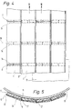
- plates 4 designed as insulating bodies are placed on the outside of a cylindrical wall 33 of a storage container 1 as shown in FIG. 1, specifically parallel to the generatrix or longitudinal axis 2 of this cylinder.
- Each plate 4 has a groove 12 in one longitudinal narrow side or side edge 6 and a connecting projection on the opposite longitudinal narrow side, e.g. a tongue 11 (Fig. 5), the tongue 11 and the groove 12 fit into each other in the same shape.
- the two parts, tongue 11 and groove 12 have an arcuate profile, an arc length of the groove 12 being greater than a semicircular arc and an arc length of the connecting projection or tongue 11 being even greater than that of the cross section of the groove, as detailed in FIG 17 is explained.
- connection approach e.g. the tongue 11 of a plate 4 is inserted into the groove 12 of the adjacent plate 4 in the longitudinal direction thereof, and the plates 4 connected in this way are placed around the wall 33 of the storage container 1, after which the insulation is already half-finished.
- each plate 4 has three reinforcing members 34 transversely to its longitudinal direction, namely one each at the plate ends or side edges 7, 8 and one in a plate center 35. Since, as shown in FIG 4. It can be seen that the plates 4 are arranged with a half offset relative to one another in terms of their length, that is to say form a "full joint", the reinforcing members 34 in the middle of the plate 35 always come between the reinforcing members 34 at the plate ends of the adjacent rows of plates 4 to lie; they thus form spatially closed, ring-like structures in horizontal planes around the cylindrical wall 33 of the large store 1.
- each reinforcing member 34 extends from an outer web 36 delimiting the groove 12 to the connecting projection of the tongue 11 at that of the outer web 36 of the adjacent plate 4 facing side edges 5.
- a screw 37 (Fig. 6) penetrates the overlapping parts namely the outer web 36 and the spring 11 of adjacent plates 4 and the ends of the reinforcing members 34 embedded therein, whereby a non-positive connection of the reinforcements takes place around the entire circumference of the cylindrical memory.
- the reinforcement of the rows of plates 4 formed in this way is able to withstand high acting suction and tensile forces due to wind pressure.
- connecting and / or reinforcing members 34 are also provided, essentially arranged and embedded in the same way as in the embodiments according to FIGS. 4 and 6.
- FIG. 7 there is a stepped stepped profile 38 on the longitudinal narrow sides or side edges 5, 6 of the plates 4, so that in the plate 4 on the left in FIG. 7, the connecting and / or reinforcing members 34 rest at their right end the plate outside, whereas its other end, i.e. the left end of the reinforcement of the plate 4 on the right in FIG. 7, lies approximately in the middle of the plate such that its outside coincides with a butt joint lying parallel to the longitudinal narrow sides of the plates 4.
- the profiling 38 is provided between the plates 4 as a kind of tongue and groove connection. Therefore, similar to FIG. 7, the left end of the reinforcing member 34 of the right plate 4 in FIG. 8 lies in the outer part of the outer web 36 on the outside of the plate, and the other end, here the right end of the reinforcing member 34 of the one in FIG. 8 left plate 4, flush with an outer side surface 40 of the spring 11th
- Laminated composite bodies also made of plastics, can be used as the material for the reinforcements or reinforcing members 20, 34.
- Foamed or extruded plastic parts can also be used.
- insulating bodies designed as plates 4 are applied, parallel to the generatrix of this cylindrical wall.
- the two parts such as tongue 11 and groove 12 have an arcuate profile, the arc length of the groove 12 being greater than a semicircular arc and the arc length of the connecting projection being even greater than that of the cross section of the groove 12, as is shown in detail in FIG. 17 and the AT-PS 377 310 is explained.
- the plates 4 are staggered in the middle in the longitudinal direction, that is to say they are laid in a “fully on joint” arrangement; the upper and lower edge parts of the plates 4 are profiled, namely with a step-like step or a fold 10.
- the connecting projection or the spring 11 of a plate 4 is inserted into the groove 12 of the adjacent plate 4 in the longitudinal direction thereof, and the connected plates 4 are placed around the wall 33 of the store, after which the insulation is already half finished is.
- each plate 4 has reinforcements protecting the rigid foam against deformation, e.g. a reinforcing member 34 made of plywood, and only on the upper edge parts, as can be seen in detail from FIGS. 11-14.
- a reinforcing member 34 made of plywood
- the reinforcing member 34 lies with its upper half in front of the steps or the fold 10
- its lower half is in the foam body Plate 4 foamed to be well anchored in it. Since, as can be seen from FIG. 9, the plates 4 are arranged half offset relative to one another with respect to their length, the steps or the fold 10 and the reinforcing members 34 always lie in the center of the plate 35 of the plate 4 adjacent to plates 41.
- each plate 4, 41 has in its plate center 35 as a recess 42 a tube which is a connection extension and / or reinforcing member 43 forms.
- This is expediently a metallic square tube which receives a transverse tendon 44 formed, for example, by a metal band.
- a tube with a round cross-section, a U-shaped profile or only a plate-shaped reinforcing member in the region of the surface delimiting the recess 42 in the direction of the wall 33. Wood, plastics or iron or. Non-ferrous metals in question.
- a length 45 of the transverse tendon 44 is slightly larger than a double width 46 of the plate 4.41, so that each metal band of a plate 4 protrudes to over half of the adjacent plates 41.
- 11 and 13 left end of the band or cross-tensioning member 44 has a widened end part as a coupling part 16, which has a toothing 47 running transversely to the longitudinal direction of the band and additionally an elongated hole 48 therein. At a distance from this toothing 47, two bores 49 are formed towards the center of the band in order to receive anchoring screws 50, as shown in the right of the two bores.
- the band of the transverse tendon 44 lies in a recess 51 between the steps of the profiled edge parts on the upper and lower end faces of the plates 4.
- a sum of the thicknesses 52 and 53 of webs 54.55 is smaller than one Thickness 56 of the plates 4.
- the right end of the cross-tensioning element 44 which is designed as a band, also has a widened end part as coupling part 17, but here with external toothing 57. Bores 49 for an anchoring screw 50 are also provided on this coupling part 17 .
- Each (right) end or coupling part 17 of a band is also assigned a spaced-apart recess 58 which extends into the upper edge part of each plate 4 through the reinforcing member 34 and the insertion of a tensioning element 59 for the cross-tensioning member designed as a band 44 e.g. a collet.
- the assembly process for fixing the plates 4 to one another is carried out as follows:
- the transverse tendon 44 then becomes the left coupling part 16 brought into engagement of the toothings 47 and 57, the elongated hole 48 making it possible to compensate for dimensional tolerances of the plates 41, and then by means of a connecting screw 50, which may have a self-tapping thread, and is inserted through the elongated hole 48 into the coupling part 17 below , a permanent connection between the via the teeth 47, 57 engaging coupling parts 16, 17 of the adjacent transverse tendons 44. In this way is the mounting of the plates 4 around the container, e.g.
- the right coupling part 17 of the last transverse tendon 44 is finally also permanently connected to the left coupling part 16 of the first transverse tendon 44 of the plate 4 by the self-tapping screw 50.
- the interconnected bands of the transverse tendons 44 around the cylindrical wall 33 of the storage container 1 form a spatial reinforcement which is closed in a circular shape and can withstand the high stresses caused by wind forces.
- the recesses 42 do not necessarily have to be formed or delimited by a tube; in some cases a U-profile or a plate can be used or this can be omitted.
- the recesses 42 can also be formed by groove-like depressions in the outer surface of the plates 4, 41; the groove bottom is then also appropriately provided with reinforcements made of plywood or the like.
- Such recesses do not necessarily have to be in the middle of the plate; e.g. they could also lie in the thirds of the long sides.
- FIG. 33 An outer wall 33 of a storage container 1 is shown in FIG.
- This wall 33 is preceded by insulation which consists of plates 4.
- These plates consist of a foam plastic body 61 and one attached to it preferably during the foaming process with this connected cover layer 62.
- connecting and / or reinforcing members 63 formed by grooves 12 and springs 11 are provided.
- the groove 12 has an arcuate cross section.
- the spring is designed with an arcuate cross section and designed in the manner of a cylinder part. The diameter of the groove 12 and the tongue 11 are the same size, so that the plates are guided into one another without play.
- an arc length 64 of the groove 12 is greater than a semicircular arc.
- An arc length 65 of the tongue 11 is greater than the arc length 64 of the cross section of the groove 12. The difference in the arc length 64 and 65 allows the pivoting range of the two plates 4 to one another to be determined. Because the arc length of the cross section of the groove 12 is greater than that of a semicircular arc, a fixed connection between the groove 11 and the tongue 12 is achieved in every possible rotational position of the groove 12 and tongue 11 relative to one another.
- FIG. 1 Another embodiment of a plate 66 is shown in FIG.
- the plate has a kink 67 and is V-shaped.
- the V-angle is only slightly less than 180 °. It is thereby achieved that the plate 66 rests on the wall 33 of the storage container 1 at two points.
- connecting and / or reinforcing members 69 formed by profiles 68 are arranged. These can be formed, for example, by extruded profiles.
- the extruded profiles are connected to the foam plastic body 61 by an adhesive process or the foam plastic body 61 is foamed onto the profiles.
- An arc length 64 of the groove 12 is again greater than that of a semicircle and the arc length 65 of the tongue 11 is greater than the arc length 64.
- plate 66 is also assigned a further connecting and / or reinforcing member 69, which is formed by a transverse tensioning member 70.
- This connecting and / or reinforcing member 69 is associated with connecting and / or reinforcing members 71, 72.
- connecting and / or reinforcing members 71, 72 are foamed into the foam plastic body 61 and protrude beyond the surface of the plate 66 facing the wall 33 of the storage container 1 - as shown for the connecting and / or reinforcing member 72 - or are in recesses 73 of these surfaces are arranged so that the connecting and / or reinforcing members 71 do not damage the wall 33 or a rust protection coating or the like applied thereon.
- the connecting and / or reinforcing members 74 consist, for example, of profiles 75, 76, which consist of extruded plastic or aluminum.
- these profiles 75, 76 are designed as hollow chamber profiles which have greater stability against deformation transverse to their longitudinal axis, as a result of which the overall strength of the plates 4 and 41 is additionally increased.
- the plates 4, 41 are thereby reinforced in the transition region in such a way that a tight seal between the plates 4, 41 is achieved even with high suction forces.
- FIG. 20 shows a modified embodiment of the profiles 75, 76, the fixing of the relative position of the profiles 75, 76 to one another being effected by a fixing pin 84.
- This fixing pin 84 can also be provided with a threaded attachment, for example a self-tapping thread, in order to connect it to the profiles 75 and 76 simultaneously, for example when inserted.
- the wall thicknesses of the profiles 75, 76 are reinforced as indicated schematically, so that there is sufficient strength against perforation.
- the fixing pin 84 can also penetrate the entire cavity 83 of the profile 75 and on the counter penetrate profiles 75 and 76 on the opposite side.
- An advantage of the illustrated design of the connecting and / or reinforcing members 74 is that the mutual telescopic guidance prevents an absolute tightness against the penetration of, in particular, water from the inside of the insulation.
- any other fixing device such as screws, spring bolts, hollow rivets or the like can of course also be used.
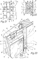
- FIGS. 21 to 23 Another embodiment variant of an insulation according to the invention using individual plates 4 is described in FIGS. 21 to 23.
- the adjacent rows running parallel to the longitudinal axis 2 of the container are each offset by half a length 85 of the plates 4.
- the connection of the individual plates 4 and 41 are now connected via profile webs which are formed by tongues and grooves and run through the length of the side edges, in the present exemplary embodiment the plates 4, 41 are mainly held by the transverse tendons 86 and longitudinal tendons 87.
- the plates 4, 41 are provided in the region of their side edges 5 and 7 with connecting and / or reinforcing members 88 and 89, respectively.
- the connecting and / or reinforcing members 88 in the region of the mutually opposite side edges 5, 6 of the plates 4, 41 are designed as half-shells.
- An inner diameter 90 of the half-shells of the connecting and / or reinforcing members 88 arranged in the region of the side edge 5 essentially corresponds to an outer diameter 91 of the connecting and / or reinforcing members 88 assigned to the side edges 6.
- An inner diameter 92 of the connecting and or or reinforcing members 88 essentially corresponds to an outer diameter 93 of the longitudinal tendon 87 which can be formed, for example, by a steel cable or by a flexible tubular body or the like.
- the longitudinal tendon 87 is formed by a tube made of plastic or metal, it can be fastened in the lower end region in a concrete foundation 94 and be supported on the wall 33 of the storage container 1 with support stamps 95.
- a concrete foundation 94 it is also possible to provide a supporting structure made of metal or similar materials in which the lower end of the steel cable or tubular body forming the longitudinal tendon 87 is anchored.
- the connection of the plates 4, 41 in the region of their mutually facing side edges 7, 8 takes place, as can be seen better from FIG. 22, via the transverse tensioning element 86, which can be a band, rope or the like that runs around the storage container 1 in the circumferential direction. As shown in the illustration in FIG.
- the connecting and / or reinforcing members 89 can additionally form a locking stop for the plates 4 arranged one above the other.
- a groove 96 is arranged in the region of the side edge 8, in which support brackets 97, which are adapted in their cross-sectional shape to the groove 96, engage.
- the transverse tensioning member 86 is also supported and brings about a positioning of the plates 4 in the radial direction in relation to the storage container 1 or its wall 33.
- the forces that occur are absorbed by the annular cross-tensioning element 86 and are distributed evenly over the connecting and / or reinforcing elements 88, 89 to the individual plates 4, 41.
- the connecting and / or reinforcing members 88, 89 are provided with anchoring parts 98 which protrude into the foam plastic body 61 of the plates 4 and 41, respectively, and are advantageously foamed into the latter.
- anchoring parts 98 which protrude into the foam plastic body 61 of the plates 4 and 41, respectively, and are advantageously foamed into the latter.
- the transverse tendon 86 runs in the area of the groove 96 when it is assigned to the side edges 7, 8 of the individual plates 4, 41, while it can run between the plate 4 and the wall 33 in the central region of the plates 4.
- the connection between the cross-tensioning element 86 and the plate 4 in the central region can be made, for example, as shown in FIG. 18 by means of connecting and / or reinforcing elements 71.
- the support against opening of the plates in the case of a negative pressure by suction is carried out exclusively by the transverse tendons, the suction forces acting on the plate surface are shared in the present exemplary embodiment on the longitudinal and transverse tendons 86 and 87 respectively.
- the transverse tendons 86 enclose the longitudinal tendons 87 on their side facing away from the wall 33 and thereby fix the side edges 7 or 8 running vertically in the present exemplary embodiment against relative movement in the suction direction via the longitudinal tendons 87.
- the transverse tendons 87 are tensioned or the longitudinal tendons 87 are also pulled or tensioned so that the plates are also held without play over the longitudinal tendons 87 in the areas between the transverse tendons.
- the longitudinal tendons 87 are arranged and prestressed at a distance corresponding to the width 46 of the plates 4, 41.
- the first row of plates is then inserted between the longitudinal tendons 87.
- the transverse tendons 86 are then mounted in the area of the longitudinal center and in the area of the ends of the first row of plates.
- the cross tendons are provisionally or finally tensioned to the desired extent.
- the next row of plates 4, 41 is inserted between the longitudinal tendons 87, the transverse tendons 86 required for this being mounted at the same time.
- the longitudinal tendons 86 are also tensioned to a predetermined extent, so that the connecting and / or reinforcing links 88 lying between the transverse tendons are held in the desired position by the tensioned longitudinal tendon 87.
- seals 100 can be arranged in the transition area, as indicated schematically.
- the connecting and / or reinforcing member 101 designed as a spring 11 is provided with a longitudinal corrugation 103.
- This longitudinal corrugation 103 is associated with an opposite longitudinal corrugation 104 in the region of the groove 12 of the connecting and / or reinforcing member 102.
- a flattening 105 ensures that the tongue 11 can be inserted more easily into the groove 12 when the plate surfaces 9 are at an extreme angle to one another.
- a full-surface guidance between tongue 11 and groove 12 is then again provided.
- a cavity 106 remaining between the flat 105 and the groove 12 can be covered with a plastic, e.g. a plastic foam 78 such as polyurethane or the like can be foamed or cast.
- the tongue 11 and the groove 12 are positively connected to one another and a change of position of the plates 4, 41 after assembly is no longer possible. This also prevents fluttering in the region of the side edges 5, 6 in the event of strong negative pressure phenomena due to suction.
- the tongue 11 and the groove 12 are each provided with a polygonal cross section, the number of corners for the groove 12 and tongue 11 being the same, or the number of corners of the groove 12 being an even multiple of the number of corners of the tongue 11.
- the number of corners of the groove 12 also determines the minimum adjustment angle by which the position of the plates 4, 41 can be changed.
- the plates 4, 41 are automatically fixed in their position after the adjustment. If the plate parts of the plate 4 adjacent to the groove 12 are designed to be elastically resilient, the plates 4, 41 can be rotated relative to one another without the spring 11 having to be removed from the groove 12.
- the springs 11 can also be provided with flats 105 in these embodiments, as indicated by dashed lines. The cavity formed between these flats 105 and the groove 12 can then be filled with a plastic 78, as described in connection with FIG. 25.
- each of the illustrated and described embodiments of the connecting and / or reinforcing members for example those described in connection with the side edges 5, 6, also for the side edges 7, 8 and vice versa, and with one another as desired to combine.
- any of the illustrated and assign versions of transverse and / or longitudinal tendons described it is possible to use reinforcing members 107 in the area of the tongues 11 and the groove 12, as shown by the two-dot-dash lines in FIG. 26.
- Reinforcing members 108 can be assigned to these in the areas of the plates 4 and 41 adjacent to the groove 12, the reinforcing members 107 and 108 of the plates 4, 41 being connected to one another by means of anchoring screws 50 so that the plate parts, which are flexible, are in their position on both sides of the groove 12 to fix to the spring 11 and to prevent the same from lifting in the event of a suction effect.
- seals 109, 110 which are formed, for example, by hollow chamber seals or lip seals.
- seals 109, 110 which are formed, for example, by hollow chamber seals or lip seals.
- moisture-tight seals can be achieved at different angular positions between the plates 4 or 41.
- the lip seals of the seal 110 if the lips are provided with corresponding internal metal reinforcements or the like, which withstand a correspondingly high negative pressure under suction. These reinforcements can be omitted if the material thickness or rigidity of the materials used is so high that the suction forces occurring with respect to their surface do not allow the seal to be lifted off.
- the transverse tendon 15 - as indicated schematically in FIG. I - consists of two parts 111, 112.
- the ends of the parts 111, 112 which are turned away from the coupling parts 16 are connected to anchoring parts 113, for example grids, barbs or other mostly flexible parts, by means of which the individual parts 111, 112 of the transverse tendons 15 are to be anchored in the interior of the plates 4, 41 .
- a length 114 of the longitudinal tendons 87 is greater than a length 85 of the individual plates 4, 41.
- the flanks delimiting the groove 12 can have different lengths, the longer flank being on the side facing away from the storage container 1 and the shorter flank on the side facing it.
- the overlapping profile parts 116, 117 of the profiles 75, 76 form sealing lips, since the two profile parts 75, 76 are guided in the manner of a telescope in the region of their profile parts 117, 116. This telescopic guide is achieved in that the profile parts 116, 117 run coaxially with the jacket of the spring 11.
- a slot 118 in the transition region between two plates, for example in the web remaining between the groove 12 and the outside of the plate.
- This slot 118 can be formed by inserting a plastic profile during the foaming process or by milling.
- a transverse channel 119 can be provided which connects the slot 118 to the recess 42.
- This slot 118 and the transverse channel 119 can be used to introduce liquid sealants after assembly, which fill the cavities remaining during assembly. Through the transverse channels 119, this liquid sealant can also penetrate into the recesses 42 and these can be filled entirely. This prevents condensation water from forming in these cavities when there are large temperature differences between the storage container and the ambient air and from becoming lodged in these areas.
- liquid sealant a slowly curing plastic foam or another type of potting compound can also be introduced.
Abstract
Description
Die Erfindung betrifft eine Isolierung für Speicherbehälter wie sie im Oberbegriff des Patentanspruches 1 beschrieben ist.The invention relates to an insulation for storage containers as described in the preamble of
Ein bekannter Speicherbehälter mit einer Isolierung - gemäß EP-A-117 338 - besteht aus vorgeformten plattenförmigen Isolierkörpern aus Hartschaumkunststoff. Sie sind bereichsweise an diesen anliegend herumgelegt, und über profilierte Teile miteinander verbunden. Diese profilierten Teile weisen im Grundriß ein kreisbogenförmiges Profil auf, wobei jede Platte an der einen Seitenkante mit einer Nut und an der gegenüberliegenden Seitenkante mit einem Verbindungsansatz versehen ist. Der Verbindungsansatz und dieA known storage container with insulation - according to EP-A-117 338 - consists of preformed plate-shaped insulating bodies made of rigid foam plastic. In some areas, they are placed against these and connected to one another via profiled parts. These profiled parts have an arcuate profile in plan, each plate being provided with a groove on one side edge and with a connecting projection on the opposite side edge. The connection approach and the
Nut passen formgleich ineinander. Da eine Bogenlänge des Verbindungsansatzes in Draufsicht größer ist als eine Bogenlänge der Nut, können einander benachbarte Platten in unterschiedliche Winkelstellungen zueinander verstellt werden. Durch diese Ausbildung der bekannten Isolierung war es einfach möglich derartige Speicherbehälter mit einem im wesentlichen fugenfreien Isoliermantel zu umgeben.Groove fit into each other in the same shape. Since an arc length of the connecting projection is larger in plan view than an arc length of the groove, adjacent plates can be adjusted to different angular positions to one another. This design of the known insulation made it possible to easily surround such storage containers with an essentially joint-free insulating jacket.
Um eine ausreichende Befestigung der Isolierung bzw. eine Ableitung der Windkräfte zu erreichen wurden außerhalb der Deckschicht umlaufende Spannbänder angeordnet, wie diese beispielsweise aus der US-A-163 347 bekannt sind. Diese außerhalb der Isolation angeordneten Spannbänder erforderten jedoch zusätzlichen Materialund beträchtlichen Arbeitsaufwand für die Montage.In order to achieve adequate fastening of the insulation or a diversion of the wind forces, circumferential tensioning straps were arranged outside the cover layer, as is known, for example, from US-A-163,347. However, these straps located outside of the insulation required additional material and considerable labor for assembly.
Bei einer weiteren bekannten Ausbildung einer Isolierung gemäß CH-A-487 480 - wird davon ausgegangen, daß eine Deckschicht verwendet wird, die eine derart hohe Widerstandsfestigkeit aufweist, daß die Sog- und Druckkräfte durch im Bereich der Stoßstellen der Platten sich einander überlappende Teile der Deckschichten, in welchen Verbindungsglieder angeordnet sind, aufgenommen werden können. Dies erfordert eine entsprechend massive Ausbildung der Deckschicht und führt dazu, daß das Gewicht einer derartigen Isolierung sehr hoch wird. Es sind damit massive Stützkonstruktionen vor allem bei höheren Speicherbehältern notwendig um das Gewicht der Isolierung aufnehmen zu können. Dazu kommt, daß die mit derartigen Deckschichten versehenen Platten jeweils nur für Speicherbehälter mit etwa gleichen Durchmesser oder für rechteckige Speicherbehälter eingesetzt werden können da bereits bei, geringer winkeliger Lage der einander benachbarten Platten die Wellungen der Deckschicht der einander benachbarten Platten nicht mehr deckungsgleich einander liegen würden, sondern vielmehr gegeneinander verkantet wären. Dies würde aber dazu führen, daß bei dem Verbinden benachbarter Platten über Verbindungsglieder eine in Richtung einer Abhebung der Platten vom Speicherbehälter wirkende Kraft auftreten würde, bzw. die Verbindungsglieder auf Abscherung beansprucht würden. Wollte man dies vermeiden, müßten die Enden der Deckschichten der einander benachbarten Platten unmittelbar vor der Montage in einem dem jeweiligen Durchmesser des zu verkleidenden Speicherbehälters angepaßten Ausmaß senkrecht zur Plattenfläche abgekantet werden um ein dekkungsgleiches Ineinanderliegen der einander überlappenden Teile der Deckschichten zu ermöglichen.In a further known embodiment of insulation according to CH-A-487 480 - it is assumed that a cover layer is used which has such a high resistance that the suction and pressure forces due to overlapping parts of the plates in the region of the joints of the plates Cover layers in which connecting links are arranged can be included. This requires a correspondingly massive formation of the cover layer and leads to the weight of such insulation becoming very high. So massive support structures are necessary, especially with higher storage tanks, to be able to absorb the weight of the insulation. In addition, the plates provided with such cover layers can only be used for storage containers of approximately the same diameter or for rectangular storage containers, since the corrugations of the cover layer of the adjacent plates would no longer be congruent with each other even with a small angular position of the adjacent plates , but would rather be tilted against each other. However, this would result in a force acting in the direction of lifting the plates from the storage container when connecting adjacent plates via connecting elements, or the connecting elements would be subjected to shearing. If one wanted to avoid this, the ends of the cover layers of the adjacent plates would have to be folded perpendicularly to the plate surface immediately before assembly to an extent adapted to the respective diameter of the storage container to be clad, in order to allow the overlapping parts of the cover layers to lie one inside the other.
Der Erfindung liegt die Aufgabe zugrunde, eine Isolierung zu schaffen, die im Stande ist neben einer guten thermischen Isolierung auch den hohen Sogkräften zufolge Winddruck bei im Freien aufgestellten Großspeichern zuverlässig standzuhalten.The invention has for its object to provide insulation that is able to withstand good wind insulation in addition to good thermal insulation due to the high suction forces in large outdoor stores.
Diese Aufgabe wird durch die im Kennzeichenteil des Patentanspruches 1 angeführten Merkmale gelöst. Durch die Zuordnung von Verbindungs- und/oder Verstärkungsgliedern im Bereich der Seitenkanten wird beim Zusammenfügen der Platten zu einer Isolierung ein in der Isolierung befindliches Verstärkungsgerippe geschaffen. Eine mit einem derartigen Verstärkungsgerippe versehene Isolierung kann den äußeren Einflüssen einen wesentlich höheren Widerstand entgegensetzen, sodaß auch bei hohen Windgeschwindigkeiten und den dabei enstehenden Sogkräften eine derart ausgebildete Isolierung eingesetzt werden kann. Vor allem durch die Verstärkung der Platten im Bereich ihrer Seitenkanten wird gleichzeitig ein dichter Abschluß der Isolierung gegen von außen eindringende Feuchtigkeit erreicht, sodaß die thermische Isolationswirkung der Isolierung über lange Zeit beibehalten werden kann. Dazu kommt, daß durch die in der Platte integrierten Verstärkungen die Platten beim Transport und beim Handling auf der Baustelle widerstandsfähiger sind und der durch Bruch von Platten entstehende Ausschuß kleingehalten werden kann.This object is achieved by the features stated in the characterizing part of
Es ist weiters auch eine Ausbildung nach Patentanspruch 2 möglich. Dadurch werden keine exzentrischen Zugkräfte auf die Platten aufgebracht.Training according to claim 2 is also possible. As a result, no eccentric tensile forces are applied to the plates.
Eine weitere Ausführungsform ist im Patentanspruch 3 beschrieben. Durch die Verwendung von den Verbindungs- und/oder Verstärkungsgliedern zugeordneten Spannvorrichtungen, insbesondere den Längs- und/oder Querspanngliedern werden die auf die Isolierung einwirkenden Belastungen immer auf mehrere Platten aufgeteilt, wodurch im Verband einer Isolierung die zur Verstärkung benötigten Teile schwächer dimensioniert werden können als wenn jede einzelne Platte die volle Belastung übernehmen müßte.Another embodiment is described in
Vorteilhaft ist aber auch eine Ausführung gemäß Patentanspruch 4, da dadurch innige Krafteinleitung in das Innere der Platten erfolgt.However, an embodiment according to
Es ist aber auch eine Ausbildung nach Patentanspruch 5 möglich, wodurch eine gute Aufteilung der auf der Angriffseite des Windes auftretenden Zugkräfte und der auf der vom Wind abgekehrten Seite auftretende Sogkräfte erzielt wird.However, an embodiment according to
Von Vorteil ist aber auch eine Weiterbildung nach Patentanspruch 6, dadadurch die Platten auch in ihren Bereichen zwischen den Querspanngliedern in einer exakten Lage zum Speicherbehälter abgestützt werden können.However, a further development according to
Es ist aber auch eine Ausbidlung gemäß Patentanspruch 7 moglich, wodurch zu den in den Platten integrierten Verbindungs- und/oder Verstärkungsgliedern gebildeten Verstärkungsgerippe ein weiteres Stütznetz durch die Längs- und Querspannglieder geschaffen wird, sodaß sich die auf die Platten einwirkenden Kräfte gleichmäßig aufteilen können.However, training is also possible, as a result of which the supporting and / or reinforcing members integrated into the plates form a further support network through the longitudinal and transverse tendons, so that the forces acting on the plates can be distributed evenly.
Eine weitere Ausführungsvariante ist im Patentanspruch 8 beschrieben. Durch diese Ausbildung ist eine rasche Verbindung der einander benachbart angeordneten Platten möglich. Zusätzlich wird durch die jeder Platte zugeordneten Quer-und/oder Längsspannglieder eine einfache Handhabung derselben erreicht, wobei durch die Verwendung von Kupplungsgliedern an den voneinander abgewendeten Enden der Quer- und/oder Längsspannglieder eine gute Kraftübertragung auf die benachbarten Platten sichergestellt wird.Another embodiment variant is described in
Vorteilhaft ist aber auch eine Ausführungsform nach Patentanspruch 9, da dadurch mit einem einzigen Querspannglied über den Umfang des Speicherbehälters das Auslangen gefunden werden kann und das Gewicht von einer Vielzahl von über den Umfang des Speicherbehälters verteilten Kupplungsvorrichtungen eingespart werden kann.However, an embodiment according to
Eine andere vorteilhafte Ausgestaltung ist im Patentanspruch 10 beschrieben, sodaß die einander zugeordneten Kupplungsteile der Kupplungsvorrichtung nur ineinander eingehängt werden müssen und nach Fertigstellung der Isolierung trotzdem ein dem gesamten Umfang des Speicherbehälters umgreifender Haltekranz geschaffen wird.Another advantageous embodiment is described in
Es ist aber auch eine Ausbildung nach Patentanspruch 11 möglich. Dadurch können die benachbarten Querspannglieder jeweils im Mittelbereich einer zwischen ihnen angeordneten Platte befestigt werden. Bei "voll auf Fug" verlegten Platten wird dadurch überdies die Möglichkeit eröffnet, nichtnur in den Endbereichen sondern auch in der Längsmitte der Platten ein Querspannglied vorzusehen.However, training according to
Es ist aber auch eine Ausführungsform nach Patentanspruch 12 möglich, wodurch die zum Befestigen der Platten benötigten Querspannglieder fest mit denselben verbunden sind und Verluste von diesen Teilen auf der Baustelle bzw. eine Uberwachung und Lagerung von zusätzlichen Bauteilen nicht notwendig ist.However, an embodiment according to
Vorteilhaft ist eine Ausführung nach Patentanspruch 13, da dadurch in die einzelnen Platten wesentlich höhere Kräfte eingeleitet werden können, als wenn nur das jeweilige Querspannglied durch das Innere der Platten verlaufen würde. Durch diese größere Oberfläche an welcher der Kunststoffschaum der Platten anhaften kann, wird auch eine höhere Ausreißfestigkeit und damit auch eine höhere Beanspruchbarkeit der Platten erzielt.An embodiment according to
Vorteilhaft ist eine Weiterbildung nach Patentanspruch 14. Dadurch können Aussparungen in den einzelnen Platten und somit Zonen mit verringertem Querschnitt vermieden werden. Überdies können die Platten gegenüber einer Ausführungsform nach welcher Aussparungen in den Platten vorgesehen sind mit einer geringeren Wandstärke ausgebildet werden.A further development according to
Die Isolierung kann aber auch nach Patentanspruch 15 weitergebildet werden, wodurch die Quer- bzw. Längsspannglieder jederzeit nachträglich mit derartigen Querspanngliedern verbunden werden können.The insulation can also be developed according to
Ein anderes Lösungsmerkmal ist im Patentanspruch 16 beschrieben, wodurch unterschiedliche auf den Speicherbehälter von außen einwirkende Temperaturen die Funktionstüchtigkeit der Querspannglieder nicht nachteilig beeinflussen können.Another solution feature is described in
Vorteilhaft ist aber auch eine Weiterbildung nach Patentanspruch 17, da dadurch jeweils in halber Höhe derselben ein Haltering integriert werden kann. Durch dieses in die Platten integrierte Verstärkungsgerippe und daß durch die Quer- bzw. Längsspannglieder gebildete Verstärkungsnetz kann auch der zur Haltung des Traggerüstes für diese Platten notwendige Aufwand vermindert werden.However, a further development according to
Es ist aber auch eine Ausführung nach Patentanspruch 18 moglich, wodurch nachträglich jederzeit ein Quer- bzw. Längsspannglied mit den Platten verbunden werden kann.However, an embodiment according to
Eine andere Ausführungsform ist im Patentanspruch 19 beschrieben, wodurch eine rasche und rutschfeste Verspannung erzielt werden kann.Another embodiment is described in claim 19, whereby a quick and non-slip bracing can be achieved.
Vorteilhaft ist aber auch eine Weiterbildung nach Patentanspruch 20, da durch die entsprechende Ausbildung der Querspannglieder keine zusätzlichen Organe benötigt werden um diese mit den Verstärkungsgliedern in den Platten zu verbinden.However, a further development according to
Weiters ist auch eine Weiterbildung nach Patentanspruch 21 möglich. Durch die Schritt für Schritt erfolgende Spannung der Querspannglieder wird bereits während dem Aufbau der Isolierung eine Versteifung der einzelnen Platten untereinander erreicht, wodurch deren Zusammenbau erleichtert wird. Darüber hinaus können beim Spannen des Spanngliedes aufgrund von großen Spannwegen eventuell auftretende Verlagerungen der Platten während des Spannens verhindert werden.Further training is also possible according to
Eine andere Ausführungsform ist im Patentanspruch 22 geoffenbart, wodurch eine einfache Verbindung der einzelnen Platten erreicht wird.Another embodiment is disclosed in
Eine andere vorteilhaften Ausgestaltung der Isolierung ist im Patentanspruch 23 beschrieben. Durch diese Ausbildung ist es möglich mit einer standardmäßig ausgebildeten Platte Speicherbehälter mit unterschiedlichen Durchmessern zu erkleiden, wobei aufgrund der durchgehenden innigen Verbindung im Bereich der Federn und Nuten eine hohe Belastbarkeit mit Sog- und Druckkräften erzielt wird. Gleichzeitig wird trotz der Möglichkeit der Anpassung der Platten an unterschiedliche Außendurchmesser eine dichte Verbindung zwischen den einzelnen Platten erreicht.Another advantageous embodiment of the insulation is described in
Weiters ist auch eine Ausbildung nach Patentanspruch 24 möglich. Jede Platte stützt sich somit an zwei in Umfangsrichtung des Behälters voneinander distanzierten Bereichen auf der Wand des Speicherbehälters ab und es können derart für die Isolierung schädliche Schwingugen leichter gedämpft werden können.Training according to
Vorteilhaft ist aber auch eine Ausbildung nach Patentanspruch 25, da dadurch das Eindringen von Feuchtigkeit auch bei hohen Winddrücken durch Fugen oder Spalten zuverlässig verhindert wird.However, an embodiment according to
Eine weitere Ausbildung der Isolierung ist im Patentanspruch 26 vorgesehen, wodurch das Entstehen von Feuchtigkeit und eine Kondenswasserbildung zwischen der Außenseite des Speicherbehälters und der Innenseite der Isolierung zuverlässig verhindert wird.A further embodiment of the insulation is provided in
Vorteilhaft ist aber auch eine Ausführung nach Patentanspruch 27, da neben der exakten Verbindung der einzelnen Platten durch die Verwendung vorgefertigter Profile auch eine erhebliche Versteifung der Platten im Bereich der Seitenkanten erzielt wird, die sich sowohl beim Transport und bei der Montage als auch im Verband der Isolierung durch eine höhere Widerstandskraft gegen Verformungen bei Sog- und Druckkräften auszeichnet.However, an embodiment according to
Von Vorteil istweiters auch eine Ausbildung nach Patentanspruch 28, da dadurch eine innige Verbindung zwischen den Profilen und dem Schaumkunststoffkörper der Platten erreicht wird.A design according to
Weiters ist auch eine Ausbildung nach Patentanspruch 29. Dadurch werden die Platten im Bereich ihrer Längsmitte verstärkt.Furthermore, there is also an embodiment according to
Eine andere Ausführungsvariante der Isolierung ist im Patentanspruch 30 beschrieben, wodurch ein relativ günstiger Verstellbereich und damit eine einfache Anpassung an unterschiedliche Durchmesser der Speicherbehälter erzielt wird.Another embodiment variant of the insulation is described in
Vorteilhaft ist auch eine Weiterbildung nach Patentanspruch 31, da durch die teleskopartige Führung ein dichter Abschluß zwischen den Profilteilen hergestellt wird.A further development according to
Eine andere Weiterbildung der Isolierung ist nach Patentanspruch 32 vorgesehen. Dadurch wird sowohl von der Innen- als auch von der Außenseite her ein dichter Abschluß zwischen den einzelnen Platten erzielt.Another development of the insulation is provided according to
Eine andere Ausführungsvariante ist nach Patentanspruch 33 vorgesehen, wodurch das Verbinden nebeneinander angeordneter Platten durch ein Inneinanderschieben in Umfangsrichtung ohne ein Einfädeln parallel zur Längsachse des Speicherbehälters möglich ist.Another embodiment variant is provided according to
Es ist aber auch eine Ausführung nach Patentanspruch 35 bei der die Verstärkungsglieder zweier einander unmittelbar benachbarter Platten mit einem beide durchsetzenden Verbindungselement verbunden werden können.But it is also an embodiment according to
Eine andere Ausführungsvariante der Isolierung ist im Patentanspruch 36 beschrieben. Die Verstärkungsglieder bilden gleichzeitig einen Schutz gegen Beschädigungen der Seitenkanten der Platten während des Transportes und der Montage.Another embodiment variant of the insulation is described in
Schließlich umfaßt die Erfindung auch ein Verfahren zur Montage einer Isolierung.Finally, the invention also includes a method for assembling insulation.
Dieses Verfahren ist durch die im Patentanspruch 39 angeführten Maßnahmen gekennzeichnet. Durch das abschnittweise Zusammensetzen der Isolierung und der in dieser angeordneten Spannglieder wird auch eine in mehreren Abschnitten voneinander unabhängig verlaufende Montage der Isolierung ermöglicht. Darüber hinaus wird durch die unmittelbar nach dem Zusammenfügen erfolgte Spannung der Querspannglieder eine Verfestigung der bereits montierten Teile der Isolierung erreicht, die die Montage der nachfolgenden Platten erleichtert.This method is characterized by the measures specified in claim 39. The section-by-section assembly of the insulation and the tendons arranged in it also enable the insulation to be installed independently in several sections. In addition, the tensioning of the transverse tendons, which takes place immediately after the assembly, results in the already assembled parts of the insulation being solidified, which facilitates the assembly of the subsequent plates.
Weitere vorteilhafte Ausführungsformen sind in den Patentansprüchen 34, 37 und 38 beschrieben.Further advantageous embodiments are described in
Zum besseren Verständnis der Erfindung wird diese im folgenden anhand mehrerer in den Zeichnungen dargestellter Ausführungsbeispiele näher erläutert.For a better understanding of the invention, it is explained in more detail below with reference to several exemplary embodiments shown in the drawings.
Es zeigen:
- Fig. 1 einen zylinderförmigen Speicherbehälter mit einer an dessen Außenseite angeordneter erfindungsgemäß ausgebildeter Isolierung in vereinfachter schematischer und schaubildlicher Darstellung;
- Fig. 2 einem Mittelbereich einer Platte der Isolierung in Stirnansicht geschnitten gemäß den Linien 11-11 in Fig. 1;
- Fig. 3 eine Verbindungsstelle zwischen zwei Querspanngliedern der Spannvorrichtung im Ubergangsbereich zwischen zwei Platten in Stirnansicht geschnitten gemäß den Linien 111-111 in Fig. 1;
- Fig. 4 einen Teil eines Speicherbehälters der mit einer erfindungsgemäß ausgebildeten Isolierung versehen ist;
- Fig. 5 den Teil des Speicherbehälters nach Fig. 4 in Draufsicht;
- Fig. 6 eine Verbindung der Platten der Isolierung des Speicherbehälters in vergrößertem Maßstab geschnitten nach den Linien VI-VI in Fig. 4;
- Fig. 7 eine Verbindung der Platten der Isolierung des Speicherbehalters in einem der Fig. 6 ahnlichen Schnitt mit einer anderen Ausführungsform der Isolierung;
- Fig. 8 eine Verbindung der Platten der Isolierung des Speicherbehälters in einem der Fig. 6 ähnlichen Schnitt der Verbindung mit einer weiteren Ausführungsvariante der Isolierung;
- Fig. 9 eine Seitenansicht eines aus vier Plattenreihen gebildeten Teilstückes einer Isolierung für einen Großspeicher;
- Fig. 10 den zugehörigen Schnitt nach den Linien X-X in Fig. 9;
- Fig. 11 einen Verbindungsbereich zwischen zwei Platten in Draufsicht teilweise geschnitten gemäß den Linien XI-XI in Fig. 9;
- Fig. 12 einen Verbindungsbereich zwischen zwei Platten in Draufsicht teilweise geschnitten gemäß den Linien XII-XII in Fig. 9;
- Fig. 13 eine Seitenansicht des in Fig. 11 dargestellten Verbindungsbereiches;
- Fig. 14 eine Seitenanischt des in Fig. 12 dargestellten Verbindungsbereiches;
- Fig. 15 eine Stirnansicht des Verbindungsbereiches im Schnitt gemäß den Linien XV-XV in Fig. 13;
- Fig. 16 eine Stirnansicht des Verbindungsbereiches im Schnitt gemäß den Linein XVI-XVI in Fig. 14;
- Fig. 17 mehrere einer äußeren Wand eines Speicherbehälters zugeordnete Platten einer erfindungsgemäßen Isolierung in Draufsicht und geschnitten;
- Fig. 18 eine Ausführungsvariante einer Platte für eine erfindungsgemäß ausgebildete Isolierung mit einem zwischen der Platte und der Wand des Speicherbehälters umlaufenden Querspannglied in Draufsicht und geschnitten;
- Fig. 19 eine Draufsicht auf eine Verbindungsstelle zwischen zwei Seitenkanten einer Platte einer erfindungsgemäßen Isolierung mit einem profilartigen Verbindungs- und bzw. oder Verstärkungsglied in Draufsicht und im Schnitt und verschiedenen Möglichkeiten zum Verschließen der nach der Montage der Platten zwischen diesen verbleibenden Schlitzen in Draufsicht und im Schnitt;
- Fig. 20 eine Draufsicht auf eine Verbindungsstelle zwischen zwei nebeneinader angeordneten Platten einer erfindungsgemäßen Isolierung mit durch Profile gebildeten Verbindungs- und bzw. oder Verstärkungsgliedern und einer möglichen Ausführungsform einer Arretierung;
- Fig. 21 eine andere Ausführungsvariante einer erfindungsgemäß ausgebildeten Isolierung für einen zylinderförmigen Speicherbehälter in vereinfachter schematischer schaubildlicher Darstellung;
- Fig. 22 die Wand des Speicherbehälters und die dieser vorgeordnete Isolierung in Stirnansicht und im Schnitt gemäß den Linien XXII-XXII in Fig. 21;
- Fig. 23 eine schaubildliche Darstellung eines Übergangsbereichs zwischen zwei nebeneinander angeordneten Platten der Isolierung gemäß Fig. 21 teilweise im Schnitt gemäß den Linien XXIII-XXIII in Fig. 21;
- Fig. 24 eine Ausführungsvariante der Verbindungs- und bzw. oder Verstärkungsglieder zwischen zwei Platten der Isolierung und diesen zugeordnete Dichtungen in Draufsicht geschnitten;
- Fig. 25 eine andere Ausführungsform der Verbindungs- und bzw. oder Verstärkungsglieder zwischen zwei Platten der Isolierung und diesen zugeordnete Dichtungen in Draufsicht geschnitten;
- Fig. 26 eine andere Ausführungsform der Verbindungs- -und bzw. oder Verstärkungsglieder zwischen zwei Platten der Isolierung in Draufsicht und im Schnitt.
- 1 shows a cylindrical storage container with an insulation designed according to the invention arranged on the outside thereof in a simplified schematic and diagrammatic representation;
- FIG. 2 shows a central region of a plate of the insulation in end view, cut along lines 11-11 in FIG. 1;
- 3 shows a connection point between two transverse tendons of the tensioning device in the transition area between two plates in front view according to lines 111-111 in FIG. 1;
- 4 shows a part of a storage container which is provided with insulation designed according to the invention;
- 5 shows the part of the storage container according to FIG. 4 in a top view;
- 6 shows a connection of the plates of the insulation of the storage container on an enlarged scale cut along the lines VI-VI in Fig. 4.
- 7 shows a connection of the plates of the insulation of the storage container in a section similar to FIG. 6 with another embodiment of the insulation;
- 8 shows a connection of the plates of the insulation of the storage container in a section of the connection similar to FIG. 6 with a further embodiment variant of the insulation;
- 9 shows a side view of a section of insulation for a large store formed from four rows of plates;
- 10 shows the associated section along lines XX in Fig. 9.
- 11 shows a connection area between two plates, in a top view, partially cut along the lines XI-XI in FIG. 9;
- 12 shows a connection area between two plates in a top view, partially cut along the lines XII-XII in FIG. 9;
- Fig. 13 is a side view of the connection area shown in Fig. 11;
- Fig. 14 is a side view of the connection area shown in Fig. 12;
- 15 shows an end view of the connection area in section along the lines XV-XV in FIG. 13;
- Fig. 16 is an end view of the connection area in section according to the lines XVI-XVI in Fig. 14;
- 17 shows a plurality of plates of an insulation according to the invention associated with an outer wall of a storage container, in plan view and in section;
- 18 shows an embodiment variant of a plate for insulation designed according to the invention with a transverse tendon running between the plate and the wall of the storage container, in a top view and in section;
- Fig. 19 is a plan view of a connection point between two side edges of a plate of insulation according to the invention with a profile-like connecting and / or reinforcing member in plan view and in section and various options for closing the remaining slots between the slits between these in plan view and in Cut;
- 20 shows a plan view of a connection point between two adjacent plates of an insulation according to the invention with connecting and / or reinforcing members formed by profiles and a possible embodiment of a locking device;
- 21 shows another embodiment variant of an insulation designed according to the invention for a cylindrical storage container in a simplified schematic diagrammatic representation;
- FIG. 22 shows the wall of the storage container and the insulation arranged upstream of it in an end view and in section along the lines XXII-XXII in FIG. 21;
- 23 shows a diagrammatic representation of a transition region between two adjacent plates of the insulation according to FIG. 21, partly in section according to lines XXIII-XXIII in FIG. 21;
- 24 shows an embodiment variant of the connecting and / or reinforcing members between two plates of the insulation and seals associated therewith cut in a top view;
- 25 shows another embodiment of the connecting and / or reinforcing members between two plates of the insulation and seals associated therewith in a top view;
- Fig. 26 shows another embodiment of the connecting and / or reinforcing members between two plates of the insulation in plan view and in section.
In Fig. 1 ist ein Speicherbehälter 1 gezeigt, der in etwa zylinderförmig ausgebildet ist und als Großspeicher beispielsweise für flüssige Stoffe wie Mineralöle, Bitumen oder verflüssigte Gase wie flüssigen Sauerstoff und Stickstoff verwendet werden kann. Eine Längsachse 2 des Speicherbehälters 1 verläuft in etwa senkrecht zu einer Aufstandsfläche 3. Der Speicherbehälter 1 kann aus Stahlblech oder Beton oder dgl. bestehen. Zur Wärmeisolierung des Speicherbehälters 1 ist dessen Außenseite mit Isolierkörpern dienenden Platten 4 umgeben.In Fig. 1, a
Die Platten 4 sind im Bereich ihrer längeren Seitenkanten 5, 6 und im Bereich ihrer kürzeren Seitenkanten 7, mit Verbindungs- und bzw. oder Verstärkungsgliedern versehen. Die Verbindungsund bzw. oder Verstärkungsglieder im Bereich der kürzeren Seitenkanten 7, 8 werden durch zu den Plattenoberflächen 9 spiegelbildlich angeordnete Falze 10 gebildet sind. Die Verbindung- und bzw. oder Verstärkungsglieder im Bereich der längeren Seitenkanten 5, 6 sind durch Federn 11 und Nuten 12 gebildet, die formgleich ineinander passen. Wie weiters nachfolgend im Detail noch beschrieben werden wird, weist ein Querschnitt der Feder 11 eine größere Bogenlänge auf als ein Querschnitt der Nut 12. Dadurch können die Platten 4 in unterschiedliche Winkelstellungen zueinander verbracht werden. Dadurch können gleichartige Platten 4 zum Verkleiden von Speicherbehältern 1 mit unterschiedlichen Außendurchmessern verwendet werden.The
Wie weiters der Zeichnung in Fig. I zu entnehmen ist werden die in Umfangsrichtung nebeneinanderliegenden Platten 4 in Richtung der Längsachse 2 jeweils um eine halbe Plattenlänge gegeneinander versetzt verlegt. Es entsteht dadurch ein Verband "Voll auf Fug". Dadurch wird eine hohe Eigensteifigkeit der Verkleidung erreicht.As can further be seen from the drawing in FIG. I, the
In den Fig. 1 bis 3 ist weiters gezeigt, daß in einem etwa gleich großen Abstand 13 von den beiden schmäleren Seitenkanten 7, 8 der Platten 4 ein Verbindungs- und bzw. oder Verstärkungsglied einer Spannvorrichtung 14 angeordnet ist. Diese Spannvorrichtung 14 umfaßt ein Querspannglied 15 welches in die Platte 4 eingeschäumt ist. Wie besser aus Fig. 2 zu ersehen ist, ist das Querspannglied 15 mit Offnungen versehen, die von dem Kunststoffmaterial der Platte 4 während des Schäumvorganges durchdrungen werden. Dadurch ist das Querspannglied 15 fest im Inneren der Platte 4 verankert und kann höhere Zugkräfte aufnehmen.1 to 3 it is further shown that a connecting and / or reinforcing member of a
Die Enden des Querspanngliedes 15 sind mit Kupplungsteilen 16, 17 kraftschlüssig verbunden.The ends of the
Wie weiters gezeigt können die Kupplungsteile 16, 17 zweier benachbarter Querspannglieder 15 miteinander verbunden werden und bilden eine Kupplungsvorrichtung 18. Die Kupplungsvorrichtung 18 kann gleichzeitig auch als Spannelemente ausgebildet sein. Es ist aber auch möglich, daß im Bereich von Stegen 19 die neben dem Falz verblieben sind, Verstärkungsglied 34 vorgesehen ist. In diesem Fall ist es möglich, die Querspannglieder 15 jeweils zu spannenund im gespannten Zustand mit dem Verstärkungsglied 20 z.B. über Nägel oder Schrauben zu verbinden, wobei durch diese Nägel oder Schrauben gleichzeitig die Verbindung der Kupplungsteile 16 und 17 von zwei benachbarten Querspanngliedern 15 erfolgen kann. Dadurch wird ein dichter und fester Zusammenhalt zwischen den einzelnen Platten 4 erreicht.As further shown, the
In Fig. 3 ist die Kupplungsvorrichtung 18 im Schnitt gezeigt. Die Kupplungsteile 16 benachbarter Querspannglieder 15 sind auf den einander zugewendeten Seiten mit Querrippen bzw. einer Verzahnung versehen. Der Kupplungsteil 17 wird durch eine Hülse gebildet, die die beiden Kupplungsteile 16 umgreift. Durch eine Verformung der Kupplungsvorrichtung 18 werden die Kupplungsteile 16, 17 zusammengepreßt und in ihrer Relativlage im gespanntem Zustand fixiert. Selbstverständich ist es auch möglich, den z.B. als Hülse Angeordneten Kupplungsteil 17 auf der den Kupplungsteilen 16 zugewandten Seite mit Querrippen einer Riffelung oder dergleichen zu versehen, sodaß es neben dem Reibungsschluß auch zu einer formschlüssigen Arretierung der Stellung der Querspannglieder 15 in der Kupplungsvorrichtung 18 kommt. Weiters ist aus der Fig. 3 ersichtlich, daß die Platten 4 im Bereich ihrer Seitenkanten 7 bzw. 8 gegengleich ausgebildet sein können. So ist einem Fortsatz 21 im Bereich der Seitenkanten 7 ein Falz 22 mit etwa gleicher Dicke zugeordnet der sich jedoch nur über einen Teil einer Höhe 23 des Fortsatzes 21 erstreckt. An diesen Falz 22 schließt eine Ausnehmung 24 an, die einen Freiraum für die Querspannglieder 15 und die Kupplungsvorrichtung 18 bildet. Eine Höhe 25 eines Fortsatzes 26 im Bereich der Seitenkante 8 ist in etwa um ein Ausmaß 27 um welches sich der Fortsatz 21 und der Falz 22 überdecken kleiner als die Höhe 23 des Fortsatzes 21. In einer Stirnkante des Fortsatzes 26 ist eine in etwa V-förmige Nut 28 vorgesehen, der ein Stützsteg 29 im Bereich der Seitenkante 7 der Platte 4 zugeordnet ist der eine gegengleiche Ausbildung aufweist. Eine Seitenfläche 30 dieses Stüztstegs 29 ist in Richtung einer Platttenoberfläche 9 geneigt, während eine Seitenfläche 31 gegen die Plattenoberfläche 9 zu in Richtung der Seitenkante 8 geneigt ist. Durch den schrägen Verlauf der Seitenfläche 30 können die Platten 4 spielfrei aufeinandergestellt werden, da durch die schräge Seitenfläche 30 eine Seitenfläche 32 des Falzes 22 gegen die dieser gegenüberliegende Seitenfläche des Fortsatzes 21 gepreßt wird. Ein eventuell in den Spalt zwischen den gegenüberliegenden Seitenflächen 31 der Nut 28 bzw. des Stützsteges 29 eindringendes Wasser bzw. eine Feuchtigkeit kann durch die schräge Gestaltung der Seitenfläche 31 nach außen und unten abrinnen. Dadurch wird das Eindringen von Feuchtigkeit in die Isolierung zusätzlich erschwert, ohne das aufwendige Dichtvorrichtungen erforderlich sind. Selbstverständlich ist es möglich, im Bereich der Seitenfläche 31 zusätzlich eine Dichtung anzuordnen, die beispielsweise aus einer Lippendichtung besteht, welche einen eventuellen Freiraum zwischen der Nut 28 und dem Stützsteg 29 verschließt oder es kann dieser Hohlraum mit Kunststoffschaum ausgefüllt werden bzw. zwischen der Seitenfläche 30 des Stützsteges 29 und der dieser gegenüberliegenden Seitenfläche des Fortsatzes 26 ein Kleber oder eine Dichtmasse eingebracht werden.In Fig. 3, the
Durch die Verwendung des Stützsteges 29 wird beim Auftreten eines Soges vor allem bei einer Windbelastung des Speicherbehälters 1 verhindert, daß sich die einander zugeordneten Seitenkanten 7, 8 voneinander lösen bzw. auslenken können und damit wird das zusätzlich zu der Wirkung der Querspannglieder 15 Risiko verringert, das einzelne Platten 4 durch den Unterdruck bzw. Sog aus dem Verband herausgerissen werden können.By using the
In den Fig 4 bis 6 sind an der Außenseite einer wie in Fig. 1 gezeigten zylindrischen Wand 33 eines Speicherbehälters 1 als Isolierkörper ausgebildete Platten 4 angelegt und zwar parallel zu der Erzeugenden bzw. Längsachse 2 dieses Zylinders. Jede Platte 4 weist in der einen Längsschmalseite bzw. Seitenkante 6 eine Nut 12 und an der gegenüberliegenden Längsschmalseite einen Verbindungsansatz z.B. eine Feder 11 auf (Fig. 5), wobei die Feder 11 und die Nut 12 formgleich ineinanderpassen. Im Grundriß weisen die beiden Teile Feder 11 und Nut 12 ein kreisbogenförmiges Profil auf, wobei eine Bogenlänge der Nut 12 größer als ein Halbkreisbogen und eine Bogenlänge des Verbindungsansatzes bzw. der Feder 11 noch größer als jene des Querschnittes der Nut ist, wie dies eingehend in der Fig. 17 erläutert ist.In FIGS. 4 to 6,
Zur Anbringung einer solchen Isolierung wird der Verbindungsansatz z.B. die Feder 11 einer Platte 4 in die Nut 12 der benachbarten Platte 4 in deren Längsrichtung eingeschoben, und die so zusammenhängenden Platten 4 werden um die Wand 33 des Speicherbehälters 1 herumgelegt, wonach die Isolierung bereits halbfertig ist.To attach such insulation, the connection approach e.g. the
Wie ferner aus den Fig. 4 und 5 ersichtlich ist, weist jede Platte 4 quer zu ihrer Längsrichtung drei Verstärkungsglieder 34 auf, und zwar je eines an den Plattenenden bzw. Seitenkanten 7, 8 und eine in einer Plattenmitte 35. Da, wie aus Fig. 4 erkenntlich, die platten 4 bezüglich ihrer Länge unter halber Versetzung zueinander angeordnet sind, also einen Verband "Voll auf Fug" bilden, kommen die Verstärkungsglieder 34 in der Plattenmitte 35 immer zwischen den Verstärkungsgliedern 34 an den Plattenenden der jeweils benachbarten Reihen von Platten 4 zu liegen; sie bilden so räumlich geschlossene, ringartige Strukturen in Horizontalebenen um die zylindrische Wand 33 des Großspeichers 1 herum.As can also be seen from FIGS. 4 and 5, each
Wie aus Fig. 5 und der vergrößerten Darstellung nach Fig. 6 ersichtlich ist, reicht jedes Verstärkungsglied 34, an seinem in Fig. 6 linken Ende, von einem die Nut 12 begrenzenden Außensteg 36 bis in den Verbindungsansatz der Feder 11 an dessen der dem Außensteg 36 der benachbarten Platte 4 zugekehrten Seitenkanten 5. Eine Schraube 37 (Fig. 6) durchsetzt dabei die sich überlappend angeordneten Teile nämlich den Außensteg 36 und die Feder 11 benachbarter Platten 4 und die darin eingebetteten Enden der Verstärkungsglieder 34, wodurch eine kraftschlüssige Verbindung der Verstärkungen um den ganzen Umfang des zylindrischen Speichers herum erfolgt. Die in dieser Weise gebildete Armierung der Reihen von Platten 4 vermag hohen einwirkenden Sog- und Zugkräften zufolge Winddruck standzuhalten.As can be seen from FIG. 5 and the enlarged representation according to FIG. 6, each reinforcing
Daß diese Ausbildung nicht nur, wie anhand der Fig. 4 und 6 beschrieben, bei Isolierungen nach dem Patent Nr. 377 310 anwendbar ist, sondern auch bei Isolierungen, deren Platten 4 an ihrer Längsschmalseite Profilierungen anderer als kreisbogenartiger Form aufweisen, ergibt sich aus den Ausführungsformen nach Fig. 7 und 8, wobei der Einfachheit halber angenommen wird, daß eine ebene Wand eines Speicherbehälters 1 zu isolieren ist.That this design can be used not only, as described with reference to FIGS. 4 and 6, for insulations according to patent no. 377 310, but also for insulations, the
In diesen beiden Fällen sind ebenfalls Verbindungs und bzw. oder Verstärkungsglieder 34 vorgesehen, im Wesen genau so angeordnet und eingebettet wie bei den Ausbildungen nach Fig. 4 und 6.In both of these cases, connecting and / or reinforcing
Nach Fig. 7 liegt eine st fenartig abgetreppte Profilierung 38 an den Längsschmalseiten bzw. Seitenkanten 5, 6 der Platten 4 vor, sodaß sich bei der in Fig. 7 linken Platte 4 die Verbindungs- und bzw. oder Verstärkungsglieder 34 an ihrem rechten Ende an der Plattenaußenseite befinden, wogegen ihr anderes Ende, also das linke Ende der Verstärkung der in Fig. 7 rechten Platte 4, in etwa in der Plattenmitte liegt, dergestalt, daß ihre Außenseite mit einer parallel zu den Längsschmalseiten der Platten 4 liegenden Stoßfuge zusammenfällt.According to FIG. 7, there is a stepped stepped
Nach Fig. 8 ist die Profilierung 38 zwischen den Platten 4 als eine Art Feder - Nut - Verbindung vorgesehen. Daher liegt, ähnlich wie nach Fig. 7, das linke Ende des Verstärkungsgliedes 34 der in Fig. 8 rechten Platte 4 im äußeren Teil des Außensteges 36 an der Plattenaußenseite, und das andere Ende, hier das rechte Ende des Verstärkungsgliedes 34 der in Fig. 8 linken Platte 4, bündig mit einer äußeren Seitenfläche 40 der Feder 11.According to FIG. 8, the
Naturgemäß kann die Ausbildung nach den Fig. 7 und 8 auch bei Speichern mit zylindrischer äußeren Wand 33 vorgesehen werden, unter Anordnung der Platten 4 zueinander unter stumpfen Winkel, wie nach Fig. 6.7 and 8 can also be provided in the case of accumulators with a cylindrical
Im Rahmen der Erfindung sind weitere Abänderungen und Ausgestaltungen an den beschriebenen Isolierungen möglich. Anstelle von Schrauben 37 als Verbindungsglieder können auch Nägel, Niete u. dgl. eingesetzt werden. Als Werkstoff für die Verstärkungen bzw. Verstärkungsglieder 20, 34 können laminierte Verbundkörper, auch aus Kunststoffen, verwendet werden. Bewährt hat sich auch Schichtholz, insbesondere Sperrholz. Es können aber auch geschäumte oder extrudierte Kunststoffteile verwendet werden. Desweiteren ist es möglich, die Verstärkungsglieder durch übergeschobene oder zumindest teilweise eingeschäumte Profilteile aus Metall z.B. Aluminium, GFK, oder Kunststoff zu bilden.Within the scope of the invention, further modifications and configurations to the insulation described are possible. Instead of
Von Vorteil ist es ferner, wenn die Außenseite der Platten 4, also ihre von der Wand 33 des Speicherbehälters 1 abgewendete Seite, mit einer Deckschicht, z.B. aus Aluminium, versehen ist.It is also advantageous if the outside of the
In Fig. 9 und 10 sind an der Außenseite einer zylindrischen Wand 33 eines Großspeichers mit vertikaler Längsachse als Platten 4 ausgebildete Isolierkörper angelegt, und zwar parallel zu der Erzeugenden dieser zylindrischen Wand. Jede Platte 4, die an ihrer Außenseite mit einer Deckschicht, z.B. aus Aluminium, versehen sein kann, weist in der einen Längsschmalseite bzw. Seitenkante 5 eine Nut 12 und an der gegenüberliegenden Längsschmalseite bzw. Seitenkante 6 einen Verbindungsansatz bzw. eine Feder 11 auf (Fig. 10), wobei der Verbindungsansatz also die Feder und die Nut 12 formgleich ineinanderpassen. Im Grundriß weisen die beiden Teile wie Feder 11 und Nut 12 ein kreisbogenförmiges Profil auf, wobei die Bogenlänge der Nut 12 größer als ein Halbkreisbogen und die Bogenlänge des Verbindungsansatzes noch größer als jene des Querschnittes der Nut 12 ist, wie dies eingehend in der Fig. 17 und der AT-PS 377 310 erläutert ist.9 and 10, on the outside of a
Die Platten 4 werden dabei, wie in Fig. 9 erkenntlich, mittig in Längsrichtung gestaffelt versetzt, also in einem Verband "Voll auf Fug" verlegt; die oberen und unteren Randteile der Platten 4 sind profiliert, nämlich mit einer stufenartigen Abtreppung bzw. einem Falz 10 ausgebildet.As can be seen in FIG. 9, the
Zur Anbringung einer solchen Isolierung wird der Verbindungsansatz bzw. die Feder 11 einer Platte 4 in die Nut 12 der benachbarten Platte 4 in deren Längsrichtung eingeschoben, und die so zusammenhängenden Platten 4 werden um die Wand 33 des Speichers herumgelegt, wonach die Isolierung bereits halb fertig ist.To apply such insulation, the connecting projection or the
Wie ferner aus Fig. 10 ersichtlich ist, weist jede Platte 4 quer zu ihrer Längsrichtung an der Abtreppung bzw. dem Falz 10 eine den Hartschaumstoff gegen Deformation schützende Verstärkungen, z.B. ein Verstärkungsglied 34 aus Sperrholz, auf, und zwar nur an den oberen Randteilen, wie dies auch im einzelnen aus den Fig. 11 -14 hervorgeht. Wie aus Fig. 15 in der der zugehörige untere profilierte Randteil der nach oben folgenden Platte 4 strichliert dargestellt ist, ersichtlich, liegt das Verstärkungsglied 34 mit seiner oberen Hälfte vor der Abtreppung bzw. dem Falz 10, und seine untere Hälfte ist in den Schaumstoffkörper der Platte 4 eingeschäumt, um darin gut verankert zu sein. Da, wie aus Fig. 9 erkenntlich, die Platten 4 bezüglich ihrer Länge unter halber Versetzung zueinander angeordnet sind, kommen immer die Abtreppungen bzw. der Falz 10 und die Verstärkungsglieder 34 in der Plattenmitte 35 der jeweils zu Platten 41 benachbarten Platte 4 zu liegen.As can also be seen from FIG. 10, each
Wie in Fig. 16 in Verbindung mit Fig. 9 gezeigt ist weist jede Platte 4, 41 in ihrer Plattenmitte 35 als Aussparung 42 ein Rohr auf, das ein Verbindungs- und bzw. oder Verstärkungsglied 43 bildet. Dieses ist zweckmäßig ein metallisches Vierkantrohr, das ein z.B. durch ein Metallband gebildetes Querspannglied 44 aufnimmt. Selbstverständlich ist es auch möglich anstelle des Vierkantrohrs ein Rohr mit rundem Querschnitt, ein U-Profil oder im Bereich der die Aussparung 42 in Richtung der Wand 33 begrenzenden Oberfläche nur ein plattenförmiges Verstärkungsglied anzuordnen. Als Material kommen sowohl Holz, Kunststoffe oder Eisen-bzw. Nichteisenmetalle in Frage. Eine Länge 45 des Querspanngliedes 44 ist etwas größer als eine doppelte Breite 46 der Platte 4,41, sodaß jedes Metallband einer Platte 4 bis über die Hälfte der jeweils benachbarten Platten 41 vorragt.As shown in FIG. 16 in connection with FIG. 9, each
Das in den Fig. 11 und 13 linke Ende des Bandes bzw. Querspanngliedes 44 weist einen verbreiterten Endteil als Kupplungsteil 16 auf, der innen eine quer zur Bandlängsrichtung verlaufende Verzahnung 47 und darin zusätzlich ein Langloch 48 aufweist. Im Abstand von dieser Verzahnung 47 sind gegen die Bandmitte hin zwei Bohrungen 49 ausgebildet, um wie bei der rechten der beiden Bohrungen gezeigt Verankerungsschrauben 50 aufzunehmen. Wie aus Fig. 15 erkenntlich, liegt das Band des Querspanngliedes 44 in einer Aussparung 51 zwischen den Abtreppungen der profilierten Randteile an den oberen und unteren Stirnseiten der Platten 4. Dazu ist eine Summe von Dicken 52 und 53 von Stegen 54,55 kleiner als eine Dicke 56 der Platten 4.11 and 13 left end of the band or
Das andere, in den Fig. 12, 14 rechte Ende des als Band ausgebildeten Querspanngliedes 44 weist ebenfalls einen verbreiterten Endteil als Kupplungsteil 17 auf, jedoch hier mit einer außenliegenden Verzahnung 57. Auch an diesem Kupplungsteil 17 sind Bohrungen 49 für je eine Verankerungsschraube 50 vorgesehen. Jedem (rechten) End- bzw. Kupplungsteil 17 eines Bandes ist weiters eine von im Abstand liegende Aussparung 58 zugeordnet, die sich in den oberen Randteil jeder Platte 4 durch das Verstärkungsglied 34 hindurch erstreckt und das Einsetzen eines Spannorganes 59 für das als Band ausgebildete Querspannglied 44 z.B. einer Spannzange, ermöglicht.The other, in FIGS. 12, 14, the right end of the
Beim Montagevorgang zur Festlegung der Platten 4 untereinander wird wie folgt vorgegangen:The assembly process for fixing the
Wenn z.B. die in Fig. 9 oberste Platte 4 zwischen die beiden ihr benachbarten Platten 41, wie eingangs beschrieben, von oben her eingeschoben worden ist, befinden sich in der dargestellten Endstellung dann die End- bzw. Kupplungsteile 16, 17 des aus der Aussparung 42 beiderseits herausragenden Bandes des Querspanngliedes 44 genau in der Mitte vor den Stegen 55 der benachbarten Platten 41, bzw. vor deren Verstärkungsglied 34. Nun wird durch die Bohrungen 49 des linken End- bzw. Kupplungsteiles 16 mindestens eine Verankerungsschraube 50 in das Verstärkungsglied 34 eingeschraubt, wodurch der linke Endteil des Bandes mit der linken benachbarten Platte 41 für dauernd verbunden ist. Hierauf erfolgt mittels einer Spannzange 59 in Fig. 14 in dünnen vollen Linien dargestellt, von der ein Zapfen 60 in die Aussparung 58 im Steg 55 bzw. dem Verstärkungsglied 34 der Platte 41 eingesetzt wird und deren andere Backe am rechten Kupplungsteil 17 des Querspanngliedes 44 angreift, ein Spannen desselben und im gespannten Zustand danach eine Festlegung des rechten Kupplungsteils 17 mittels mindestens einer weiteren Verankerungsschraube 50 in einer der Bohrungen 49. Bei der (nach rechts) neben der Platte 41 folgenden weiteren Platten 4 wird dann das Querspannglied 44 mit dem linken Kupplungsteil 16 in gegenseitigen Eingriff der Verzahnungen 47 und 57 gebracht, wobei das Langloch 48 einen Ausgleich bezüglich Dimensionstoleranzen der Platten 41 ermöglicht, und dann wird mittels einer Verbindungsschraube 50, die ein selbstschneidendes Gewinde aufweisen kann und durch das Langloch 48 in den darunterliegenden Kupplungsteil 17 eingeführt wird, eine dauernde Verbindung zwischen den über die Verzahnungen 47, 57 in Eingriff stehenden Kupplungsteile 16, 17 der benachbarten Querspannglieder 44 hergestellt. Ist in dieser Weise die Montage der Platten 4 um den Behälter herum, z.B. in einer Reihe oder sektorweise, fertiggestellt, wird ebenso schließlich der rechte Kupplungsteil 17 des letzten Querspanngliedes 44 mit dem linken Kupplungsteil 16 des ersten Querspanngliedes 44 der Platte 4 durch die ein selbstschneidendens Gewinde aufweisende Verankerungsschraube 50 für dauernd verbunden. Dadurch wird durch die so untereinander verbundenen Bänder der Querspannglieder 44 um die zylindrische Wand 33 des Speicherbehälters 1 herum eine räumliche, in kreisringform geschlossene Armierung gebildet, die den hohen Beanspruchungen durch auftretende Windkräfte standzuhalten vermag.If e.g. 9, the
Im Rahmen der Erfindung sind mannigfaltige Abänderungen und Ausgestaltungen an dem beschriebenen Ausführungsbeispiel möglich. Als Verstärkungsteile können anstelle von Sperrholz oder Schichtholz auch andere schraubbare Werkstoffe, wie laminierte Verbundkörper, auch aus Kunststoffen, eingesetzt werden. Die Verbindung der Bänder bzw. der Querspannglieder 15 untereinander kann auch durch Haken erfolgen; ferner können hiefür Spannschlösser oder Bajonettverschlüsse eingesetzt werden.Various modifications and refinements to the described exemplary embodiment are possible within the scope of the invention. Instead of plywood or plywood, other screwable materials, such as laminated composite bodies, also made of plastics, can be used as reinforcing parts. The connection of the bands or the
Die Aussparungen 42 müssen nicht unbedingt durch ein Rohr gebildet bzw. begrenzt sein; in manchen Fällen kann ein U-Profil oder eine Platte verwendet oder dieses auch weggelassen werden. Auch können die Aussparungen 42 durch nutartige Vertiefungen in der Außenfläche der Platten 4, 41 gebildet sein; der Nutboden ist dann ebenfalls zweckmäßig mit Verstärkungen aus Sperrholz od. dgl. versehen. Solche Aussparungen müssen nicht unbedingt in Plattenmitte liegen; sie könnten z.B. auch in den Dritteln der Längsschmalseiten liegen.The
In Fig. 17 ist eine äußere Wand 33 eines Speicherbehälters 1 gezeigt. Dieser Wand 33 ist eine Isolierung vorgeordnet die aus Platten 4 besteht. Diese Platten bestehen aus einem Schaumkunststoffkörper 61 und einer auf diese aufgebrachten vorzugsweise beim Schäumvorgang mit dieser verbundenen Deckschicht 62. Zur Verbindung der Platten 4 im Bereich ihrer Seitenkanten 5, 6 sind durch Nuten 12 und Federn 11 gebildete Verbindungs- und bzw. oder Verstärkungsglieder 63 vorgesehen. Um die Platten 4 für die Isolierung von Speicherbehältern 1 mit unterschiedlichen Durchmessern verwenden zu können weist die Nut 12 einen kreisbogenförmigen Querschnitt auf. Ebenso ist die Feder mit einem kreisbogenförmigen Querschnitt ausgebildet und in Art eines Zylinderteils ausgeführt. Die Durchmesser der Nut 12 und der Feder 11 sind gleich groß, sodaß die Platten spielfrei ineinandergeführt sind. Um die Verschwenkung der Platten 4 in radialer Richtung relativ zum Speicherbehälter 1 zu ermöglichen, ist eine Bogenlänge 64 der Nut 12 größer als ein Halbkreisbogen. Eine Bogenlänge 65 der Feder 11 ist größer als die Bogenlänge 64 des Querschnittes der Nut 12. Durch die Differenz der Bogenlänge 64 und 65 kann der Verschwenkbereich der beiden Platten 4 zueinander festgelegt werden. Dadurch, daß die Bogenlänge des Querschnittes der Nut 12 größer ist als die eines Halbkreisbogens wird in jeder möglichen Drehstellung der Nut 12 und Feder 11 relativ zueinander eine fixe Verbindung zwischen Nut 11 und Feder 12 erreicht.An
In Fig. 18 ist eine andere Ausführungsform einer Platte 66 gezeigt. Die Platte weist einen Knick 67 auf und ist V-förmig ausgebildet. Der V-Winkel ist nur wenig kleiner als 180°. Dadurch wird erreicht, daß die Platte 66 an zwei Stellen auf der Wand 33 des Speicherbehälters 1 anliegt. Im Bereich der Seitenkanten 5, 6 sind durch Profile 68 gebildete Verbindungs- und bzw. oder Verstärkungsglieder 69 angeordnet. Diese können beispielsweise durch extrudierte Profile gebildet sein. Die extrudierten Profile werden mit dem Schaumkunststoffkörper 61 durch einen Klebevorgang verbunden oder der Schaumkunststoffkörper 61 wird an die Profile angeschäumt. Eine Bogenlänge 64 der Nut 12 ist wieder größer als die eines Halbkreises und die Bogenlänge 65 der Feder 11 ist größer als die Bogenlänge 64. Dadurch wird der gleiche Effekt wie er bereits bei den Platten 4 in Fig. 17 beschrieben wurde erreicht. Der Platte 66 ist aber noch ein weiteres Verbindungs- und bzw. oder Verstärkungsglied 69 zugeordnet, welches durch ein Querspannglied 70 gebildet ist. Diesem Verbindungs- und bzw. oder Verstärkungsglied 69 sind Verbindungs- und bzw. oder Verstärkungsglieder 71, 72 zugeordnet. Diese Verbindungs- und bzw. oder Verstärkungsglieder 71, 72 sind in den Schaumkunststoffkörper 61 eingeschäumt und ragen über die der Wand 33 des Speicherbehälters 1 zugewandte Oberfläche der Platte 66 - wie beim Verindungs-und bzw. oder Verstärkungsglied 72 gezeigt - vor oder sind in Ausnehmungen 73 dieser Oberflächen angeordnet, sodaß durch die Verbindungsund bzw. oder Verstärkungsglieder 71 die Wand 33 oder eine darauf aufgebrachte Rostschutzbeschichtung oder dgl. nicht beschädigt wird.Another embodiment of a
In Fig. 19 ist eine Ausführungsform von Verbindungs- und bzw, oder Verstärkungsgliedern 74 gezeigt, welche den Seitenkanten 5 bzw. 6 von benachbarten Platten 4, 41 zugeordnet ist. Die Verbindungs- und bzw. oder Verstärkungsglieder 74 bestehen beispielsweise aus Profilen 75, 76, die aus extrudiertem Kunststoff bzw. aus Aluminium bestehen. Im dargestellten Ausführungsbeispiel sind diese Profile 75, 76 als Hohlkammerprofile ausgebildet, die gegen eine Verformung quer zu ihrer Längsachse eine höhere Stabilität aufweisen, wodurch die Gesamtfestigkeit der Platten 4 bzw. 41 zusätzlich erhöht wird. Außerdem werden dadurch die Platten 4, 41 im Übergangsbereich derart verstärkt, daß auch bei hohen Sogkräften ein dichter Abschluß zwischen den Platten 4, 41 erreicht wird. Um die Platten 4,41 in ihrer jeweiligen Winkellage in Abhängigkeit vom Radius bzw. Durchmesser des Speicherbehälters 1 zu fixieren ist es wie in Fig. 19 beispielsweise gezeigt, möglich, einen Hohlraum 77 mit schematisch durch Schraffur angedeuteten Kunststoffschaum 78 auszuschäumen um die Position oder die relative Stellung der Profile 75, 76 zueinander zu fixieren. Um den beim Schäumvorgang auftretenden Schäumdruck entgegenzuwirken ist es auf der der Wand 33 zugewendeten Seite der beiden Profile 75, 76 möglich ein Distanzstück 79 z.B. einen Keil oder dgl. einzusetzen. Überdies können im Bereich des Distanzstückes 79 sich gegenseitig überlappende Dichtlippen 80 vorgesehen sein, wobei bei einer dichten Ausbildung oder Führung der Dichtlippen 80 aneinander auch dieser Zwischenraum gleichzeitig ausgeschäumt werden kann. Um den Kunststoffschaum 78 in dem Hohlraum 77 ausreichend zu verankern ist es wie mit strichlierten Linien angedeutet, möglich, in dem Profil 75 oder am Profil 76 Verankerungsstege 81 anzuordnen, sodaß sich der Kunststoffschaum 78 in dem Hohlraum 77 festsetzen kann. Unter anderem ist es aber auch möglich, die Hohlkammern 82, 83 mit einem Kunststoffschaum 78 zu füllen, sodaß eine ununterbrochene Isolierwirkung über die gesamte Isolierung auch in dem Bereich zwischen den Kunststoffkörpern der Platten 4, 41 erreicht wird. Dies kann beispielsweise dadurch erfolgen, daß wie schematisch angedeutet, Öffnungen in den zwischen den Platten 4, 41 und den Hohlräumen 82, 93 liegenden Stegen der Profile 75, 76 angeordnet werden.19 shows an embodiment of connecting and / or reinforcing
In Fig. 20 ist eine abgeänderte Ausführungsform der Profile 75, 76 gezeigt, wobei die Fixierung der Relativstellung der Profile 75, 76 zueinander durch einen Fixierstift 84 erfolgt. Dieser Fixierstift 84 kann auch mit einem Gewindeansatz beispielsweise einem selbstschneidenden Gewinde versehen sein, um ihn beispielsweise beim Einsetzen gleichzeitig mit den Profilen 75 und 76 zu verbinden. Dazu sind die Wandstärken der Profile 75, 76 wie schematisch angedeutetverstärkt, sodaß eine ausreichende Festigkeit gegen Lochlaibung entsteht. Wie weiters durch strichlierte Linien schematisch angedeutet kann der Fixierstift 84 auch den gesamten Hohlraum 83 des Profils 75 durchsetzen und auf der gegenüberliegenden Seite die Profile 75 und 76 durchdringen.20 shows a modified embodiment of the
Selbstverständlich ist es bei dieser Ausführungsform ebenso möglich, die mit gleichen Bezugszeichen bezeichneten Hohlkammern 82 und 83 der Profile 75, 76 mit Kunststoffschaum zu füllen bzw. zusätzlich in den Hohlraum 77 Kunststoffschaum oder ein Distanzstück einzubringen.Of course, in this embodiment it is also possible to fill the
Ein Vorteil der dargestellten Ausbildung der Verbindungs- und bzw. oder Verstärkungsglieder 74 liegt darin, daß durch die gegenseitige teleskopartige Führung eine absolute Dichtheit gegen das Eindringen insbesondere von Schlagwasser in den Innenraum der Isolierung vermieden wird.An advantage of the illustrated design of the connecting and / or reinforcing
Anstelle des dargestellten Fixierstiftes 84 können selbstverständlich auch beliebige andere Fixiereinrichtung wie Schrauben, Federbolzen, Hohlnieten oder dgl. verwendet werden.Instead of the fixing
In den Fig. 21 bis 23 ist eine andere Ausführungsvariante einer erfindungsgemäßen Isolierung unter Verwendung von einzelnen Platten 4 beschrieben. Wie bereits anhand der Fig. I, 4 und 9 erläutert werden die parallel zur Längsachse 2 des Behälters verlaufenden nebeneinanderliegenden Reihen jeweils um die Hälfte einer Länge 85 der Platten 4 versetzt. Während nun bei den Ausführungsformen gemäß den Fig. I bis 20 die Verbindung der einzelnen Platten 4 bzw. 41 über durch Federn und Nuten gebildete über die Länge der Seitenkanten durchlaufende Profilstege verbunden sind, erfolgt die Halterung der Platten 4, 41 beim vorliegenden Ausführungsbeispiel hauptsächlich durch die Querspannglieder 86 und Längsspannglieder 87. Die Platten 4, 41 sind im Bereich ihrer Seitenkanten 5, und der Seitenkanten 7 mit Verbindungs- und bzw. oder Verstärkungsgliedern 88 bzw. 89 versehen. Die Verbindungs- und bzw. oder Verstärkungsglieder 88 im Bereich der einander gegenüberliegenden Seitenkanten 5, 6 der Platten 4, 41 sind als Halbschalen ausgebildet. Ein Innendurchmesser 90 der Halbschalen der im Bereich der Seitenkante 5 angeordneten Verbindungs- und bzw. oder Verstärkungsglieder 88 entspricht im wesentlichen einem Außendurchmesser 91 der den Seitenkanten 6 zugeordneten Verbindungsund bzw. oder Verstärkungsglieder 88. Ein Innendurchmesser 92 der mit der Seitenkante 6 verbundenen Verbindungs- und bzw. oder Verstärkungsglieder 88 entspricht im wesentlichen einem Außendurchmesser 93 des Längsspanngliedes 87 welches beispielsweise durch ein Stahlseil oder durch einen flexiblen Rohrkörper oder dgl. gebildet sein kann. Vor allem dann wenn das Längsspannglied 87 durch ein Rohr aus Kunststoff oder Metall gebildet ist kann dieses im unteren Endbereich in einem Betonfundament 94 befestigt sein und sich mit Stüztstempeln 95 auf der Wand 33 des Speicherbehälters 1 abstützen. Selbstverständlich ist es möglich, anstelle des Betonfundaments 94 auch eine Tragkonstruktion aus Metall oder ähnlichen Materialien vorzusehen, in der das untere Ende des das Längsspannglied 87 bildenden Stahlseiles oder Rohrkörpers verankert ist. Die Verbindung der Platten 4, 41 im Bereich ihrer einander zugewendeten Seitenkanten 7, 8 erfolgt wie besser aus Fig. 22 zu ersehen ist über das Querspannglied 86 welches ein in Umfangsrichtung um den Speicherbehälter 1 umlaufendes Band, Seil oder dgl. sein kann. Wie in der Darstellung in Fig. 22 gezeigt können dabei zusätzlich die Verbindungs- und bzw. oder Verstärkungsglieder 89 einen Verriegelungsanschlag für die übereinander angeordneten Platten 4 bilden. Dazu ist im Bereich der Seitenkante 8 eine Nut 96 angeordnet, in die in ihrer Querschnittsform der Nut 96 angepaßte Stützbügel 97 eingreifen. Gegen diese Stützbügel des Verbindungs- und bzw. oder Verstärkungsgliedes 89 stützt sich auch das Querspannglied 86 ab und bewirkt eine Positionierung der Platten 4 in radialer Richtung bezogen auf den Speicherbehälter 1 bzw. dessen Wand 33. Dadurch wird auch bei starken Unterdrücken im Bereich der Silo-Oberfläche bei starken Stürmen ein Flattern der Platten 4 im Bereich der einander zugewandten Seitenkanten 7 und 8 zuverlässig ausgeschaltet. Die dabei auftretenden Kräfte werden durch das ringförmige Querspannglied 86 aufgenommen und verteilen sich gleichmäßig über die Verbindungs- und bzw. oder Verstärkungsglieder 88,89 auf die einzelnen Platten 4,41.Another embodiment variant of an insulation according to the invention using
Die Verbindungs- und bzw. oder Verstärkungsglieder 88, 89 sind mit Verankerungsteilen 98 versehen, die in den Schaumkunststoffkörper 61 der Platten 4 bzw, 41 hineinragen und in vorteilhafter Weise in diese eingeschäumt sind. Es ist aber ebenso möglich in den Platten Ausnehmungen vorzusehen in welchen mittels eines gießfähigen Harzes oder Klebers die Verbindungs- und bzw. oder Verstärkungsglieder 88, 89 befestigt werden.The connecting and / or reinforcing
Wie am besten aus Fig. 23 ersichtlich verläuft das Querspannglied 86 wenn es den Seitenkanten 7, 8 der einzelnen Platten 4, 41 zugeordnet ist im Bereich der Nut 96 während es im Mittelbereich der Platten 4 zwischen der Platte 4 und der Wand 33 verlaufen kann. Die Verbindung zwischen dem Querspannglied 86 und der Platte 4 im Mittelbereich kann beispielsweise wie in Fig. 18 gezeigt durch Verbindungs- und bzw. oder Verstärkungsglieder 71 erfolgen.As best seen in FIG. 23, the
Wie jedoch weiters mit strichlierten Linien in Fig. 22 angedeutet ist es auch möglich im Mittelbereich der Platten 4, 41 eine Ausnehmung 99 vorzusehen, durch die das Querspannglied 86 hindurchgeführt wird. Zwischen dem Querspannglied 86 und der diesen in Richtung der Wand 33 zugeordneten Oberfläche der Ausnehmung 99 kann ein Verstärkungsglied 34 wie das anhand der Fig. 10 bis 16 beschrieben wurde vorgesehen sein. Ebenso ist es aber auch möglich, das Querspannglied 86 wie in Verbindung mit Fig. 2 und 3 beschrieben in den Kunststoffschaumkörper der Platten 4, 41 einzuschäumen. Während bei den Ausführungsformen gemäß den Fig. I bis 20 die Abstützung gegen ein Öffnen der Platten bei einem Unterdruck durch Sogwirkung ausschließlich durch die Querspannglieder erfolgt teilen sich die auf die Plattenoberfläche einwirkenden Sogkräfte bei dem vorliegenden Ausführungsbeispiel auf die Längs- und Querspannglieder 86 bzw. 87 auf. Dazu umfassen die Querspannglieder 86 die Längsspannglieder 87 auf ihrer von der Wand 33 abgewendeten Seite und fixieren dadurch über die Längsspannglieder 87 die im vorliegenden Ausführungsbeispiel vertikal verlaufenden Seitenkanten 7 oder 8 gegen eine Relativbewegung in Sogrichtung ab. Nachdem oder bevor die Querspannglieder 87 gespannt sind bzw. werden werden auch die Länsspannglieder 87 straff gezogen bzw. gespannt sodaß auch in den Bereichen zwischen den Querspanngliedern die Platten über die Längsspannglieder 87 spielfrei gehaltert sind.However, as further indicated by dashed lines in FIG. 22, it is also possible to provide a
Die Verlegung der Platten 4, 41 deren Seitenkanten durch die Verbindungs- und bzw. oder Verstärkungsglieder 88,89 versteift sind und welchen ein durch die Längs- bzw. Querspannglieder gebildetes zusätzliches Verstärkungsnetz überlagert wird erfolgt nun folgender Maßen:The laying of the
Zuerst werden in einem der Breite 46 der Platten 4, 41 entsprechenden Abstand die Längsspannglieder 87 angeordnet und vorgespannt. Danach wird die erste Reihe der Platten zwischen den Längsspanngliedern 87 eingesetzt. Dann werden im Bereich der Längsmitte und im Bereich der Enden der ersten Plattenreihe die Querspannglieder 86 montiert. Diese werden je nachdem ob die Isolierung über den Umfang des Speicherbehälters in einem Arbeitsgang oder in mehreren nebeneinanderliegenden Bereichen aufgebracht wird die Querspannglieder provisorisch oder entgültig in dem gewünschten Ausmaß gespannt. Nun wird die nächste Reihe der Platten 4, 41 zwischen die Längsspannglieder 87 eingefügt, wobei gleichzeitig die dazu benötigten Querspannglieder 86 montiert werden. Ist die Isolierung fertiggestellt werden auch die Längsspannglieder 86 auf ein vorbestimmtes Maß gespannt, soda8 die zwischen den Querspanngliedern liegenden Verbindungs- und bzw. oder Verstärkungsglieder 88 durch das gespannte Längsspannglied 87 in der gewünschten Position gehalten werden.First, the
Um auch bei dieser Ausführungsform bei welcher sich die Schaumkunststoffkörper 61 nicht direkt überlappen eine entsprechende Abdichtung zwischen diesen zu erzielen können im Ubergangsbereich wie schematisch angedeutet Dichtungen 100 angeordnet sein.In order to achieve a corresponding seal between them in this embodiment, too, in which the
In den Fig. 24 bis 26 sind weiters unterschiedliche Ausbildungen der Federn 11 und Nuten 12 von Verbindungs- und bzw. oder Verstärkungsgliedern 101, 102 gezeigt, die bevorzugt im Verlauf der vertikalen Seitenkanten 5, 6 der Platten 4, 41 angeordnet sind. Vor allem soll durch diese Gestaltung die Verstellbarkeit der ineinander geführten Verbindungs- und bzw. oder Verstärkungsglieder 101, 102 in ihrer jeweiligen winkeligen Lage zueinander feststellbar sein. Dazu ist das als Feder 11 ausgebildete Verbindungs- und bzw. oder Verstärkungsglied 101 mit einer Längsriffelung 103 versehen. Dieser Längsriffelung 103 ist im Bereich der Nut 12 des Verbindungsund bzw. oder Verstärkungsgliedes 102 eine gegengleiche Längsriffelung 104 zugeordnet. Dadurch können die beiden Platten 4, 41 relativ feinfühlig um geringe Winkelschritte zueinander verstellt werden und sind in ihrer jeweiligen Position durch die Längsriffelung automatisch arretiert.24 to 26 also show different designs of the
Bei der Ausführungsform in Fig. 25 wird durch eine Abflachung 105 erreicht, daß bei einer extremen Winkelstellung der Plattenoberflächen 9 zueinander die Feder 11 leichter in die Nut 12 eingesetzt werden kann. Bei einem Verdrehen in ihre in Fig. 25 gezeigte Gebrauchslage ist dann wieder eine vollflächige Führung zwischen Feder 11 und Nut 12 gegeben. Um auch bei einer derartigen Ausgestaltung der Verbindungs- und bzw. oder Verstärkungsglieder 101, 102 eine formschlüssige Verbindungs- bzw. Arretierung sicherzustellen kann ein zwischen der Abflachung 105 und der Nut 12 verbleibender Hohlraum 106 mit einem Kunststoff z.B. einem Kunststoffschaum 78 wie Polyurethan oder dgl. ausgeschäumt oder gegossen werden. Dadurch werden die Feder 11 und die Nut 12 formschlüssig miteinander verbunden und eine Stellungsveränderung der Platten 4,41 nach der Montage ist nicht mehr möglich. Dadurch wird auch verhindert, daß es im Bereich der Seitenkanten 5, 6 bei starken Unterdruckerscheinungen durch Sogwirkung zu einem Flattern kommen kann.In the embodiment in FIG. 25, a flattening 105 ensures that the
In Fig. 26 ist die Feder 11 und die Nut 12 jeweils mit einem mehreckigen Querschnitt versehen, wobei die Anzahl der Ecken bei Nut 12 und Feder 11 gleich ist, oder die Eckenzahl der Nut 12 ein gerades Vielfaches der Eckenzahl der Feder 11 haben kann.26, the
Durch die Anzahl der Ecken der Nut 12 wird gleichzeitig auch der minimale Verstellwinkel, um den die Platten 4, 41 in ihrer Lage zueinander veränderbar sind, festgelegt. Auch bei dieser Ausführungsform werden die Platten 4, 41 nach der Verstellung automatisch in ihrer Lage fixiert. Bei entsprechend elastisch federnd nachgebender Ausbildung der der Nut 12 benachbarten Plattenteile der Platte 4 kann eine Verdrehung der Platten 4, 41 zueinander erfolgen, ohne das die Feder 11 aus der Nut 12 entfernt werden muß. Um auch bei den Ausführungsformen nach den Fig, 24 und 26 eine formschlüssige Verbindung zwischen den Platten 4, 41 herzustellen, können die Federn 11 auch bei diesen Ausführungsformen mit Abflachungen 105-wie mit strichlierten Linien angedeutet - versehen sein. Der zwischen diesen Abflachungen 105 und der Nut 12 gebildete Hohlraum kann dann wie in Verbindung mit Fig. 25 beschrieben durch einen Kunststoff78 ausgefüllt werden.The number of corners of the
Im Rahmen der Erfindung ist es selbstverständlich möglich, jede der dargestellten und beschriebenen Ausführungsformen der Verbindungs- und bzw. Verstärkungsglieder also beispielsweise solche die in Verbindung mit den Seitenkanten 5, 6 beschrieben wurden auch für die Seitenkanten 7, 8 und umgekehrt zu verwenden und beliebig miteinander zu kombinieren. Gleichermaßen ist es unabhängig von der Ausbildung der Verbindungs- und bzw. oder Verstärkungsglieder möglich, diesen jede beliebige der dargestellten und beschriebenen Ausführungen von Quer- und bzw. oder Längsspanngliedern zuzuordnen. Auch ist es beispielsweise möglich im Bereich der Federn 11 und der Nut 12 Verstärkungsglieder 107 wie mit strich-zwei-punktierten Linien in Fig. 26 dargestellt zu verwenden. Diesen können in den der Nut 12 benachbarten Bereichen der Platten 4 bzw. 41 Verstärkungsglieder 108 zugeordnet sein, wobei die Verstärkungsglieder 107 und 108 der Platten 4, 41 mittels Verankerungsschrauben 50 miteinander verbunden werden um damit die ansich nachgiebigen Plattenteile beidseits der Nut 12 in ihrer Lage zur Feder 11 zu fixieren und ein Abheben derselben bei einer Sogwirkung zu verhindern.Within the scope of the invention, it is of course possible to use each of the illustrated and described embodiments of the connecting and / or reinforcing members, for example those described in connection with the side edges 5, 6, also for the side edges 7, 8 and vice versa, and with one another as desired to combine. Similarly, regardless of the design of the connecting and / or reinforcing members, it is possible to use any of the illustrated and assign versions of transverse and / or longitudinal tendons described. It is also possible, for example, to use reinforcing
In den Fig. 24 bis 26 sind dann auch noch weitere Ausführungs- und Anordnungsmöglichkeiten für Dichtungen 109, 110 die beispielsweise durch Hohlkammerdichtungen bzw. Lippendichtungen gebildet sind, dargestellt. Wie insbesondere aus der Darstellung in Fig. 25 ersichtlich, können bei entsprechender Anordnung derartiger durch Hohlkammerdichtungen gebildete Dichtungen 109 bei unterschiedlichen Winkelstellungen zwischen den Platten 4 bzw. 41 feuchtigkeitsdichte Abdichtungen erreicht werden. Gleiches trifft auf die Lippendichtungen der Dichtung 110 zu wenn die Lippen mit entsprechenden innenliegenden Metallverstärkungen oder dgl. versehen sind, die einem entsprechend hohem Unterdruck bei Sogwirkung standhalten. Diese Verstärkungen können dann wegfallen, wenn die Materialstärke bzw. Steifigkeit der verwendeten Materialien so hoch ist, daß die bezogen auf ihre Oberfläche auftretenden Sogkräfte ein Abheben der Dichtung nicht ermöglichen.24 to 26 also show further design and arrangement options for
Desweiteren ist es im Rahmen der vorliegenden Erfindung auch möglich, daß das Querspannglied 15 - wie in Fig. I schematisch angedeutet - aus zwei Teilen 111, 112 besteht. Die von den Kupplungsteilen 16 abgewendeten Enden der Teile 111, 112 sind mit Verankerungsteilen 113 beispielsweise Gitternetzen, Widerhaken oder sonstigen meist flexilben flächenhaften Teilen verbunden durch die die Verankerung der einzelnen Teile 111, 112 der Querspannglieder 15 im Inneren der Platten 4, 41 sichergestellt werden sollen.Furthermore, it is also possible within the scope of the present invention that the transverse tendon 15 - as indicated schematically in FIG. I - consists of two
Weiters ist aus der Darstellung in Fig. 21 ersichtlich, daß eine Länge 114 der Längsspannglieder 87 größer ist als eine Länge 85 der einzelnen Platten 4, 41.Furthermore, it can be seen from the illustration in FIG. 21 that a
Nach einer weiteren Ausführungsvariante der vorliegenden Erfindung ist es aber auch möglich, daß wie in Fig. 17 schematisch angedeutet zwischen der Außenseite der Wand 33 des Speicherbehälters 1 und der Innenseiten der Platten 4, 41 gegebenenfalls vorhandene Zwischenräume 115 mit einem Schaumstoff beispielsweise einen Einkomponenten-Schaumstoff gefüllt werden. Dies erfolgt derart, daß nach dem Fertigstellen der Isolierung in diese Zwischenräume 114 der Kunststoff in flüssiger Form eingebracht wird, dort aufschäumt und dadurch die Zwischenräume 115 vollflächig füllt. Ein weiterer Vorteil dieser Lösung liegt darin, daß durch die beim Aufschäumen des Kunststoffs entstehende Volumsvergrö- ßerung eine Schubkraft auf die Platten 4, 41 in Richtung der Querspannglieder 15, 44, 70, 86 ausgeübt wird, sodaß es zu einer Vorspannung dieser Querspannglieder kommt. Dadurch wird jegliches Spiel zwischen den Platten 4, 41 der Wand 33 und den Querspanngliedern 15 ausgeschaltet. Dadurch ist es auch nach einer längeren Einsatzdauer kaum möglich, daß sich die Platten 4, 41 lockern.According to a further embodiment variant of the present invention, it is also possible that, as indicated schematically in FIG. 17, between the outside of the
Wie weiters den Fig. 19 und 20 zu entnehmen ist, können die die Nut 12 begrenzenden Flanken verschieden lang sein, wobei die längere Flanke an der dem Speicherbehälter 1 abgewendeten und die kürzer Flanke an der diesem zugewandten Seite liegt. Desweiteren bilden die einander überdeckenden Profilteile 116, 117 der Profile 75, 76 Abdichtlippen, da die beiden Profilteile 75, 76 im Bereich ihrer Profilteile 117, 116 in Art eines Teleskop geführt sind. Diese Teleskopführung wird dadurch erreicht, daß die Profilteile 116, 117 koaxial zum Mantel der Feder 11 verlaufen.19 and 20, the flanks delimiting the
Desweiteren ist es im Rahmen der Erfindung möglich, wie beispielsweise in den Fig. 12 und 13 gezeigt im Übergangsbereich zwischen zwei Platten beispielsweise in den zwischen der Nut 12 und der Außenseite der Platte verbleibenden Steg einen Schlitz 118 anzuordnen. Dieser Schlitz 118 kann durch Einlegen eines Kunststoffprofiles während des Schäumvorganges oder durch eine Ausfräsung gebildet sein.Furthermore, it is possible within the scope of the invention, as shown for example in FIGS. 12 and 13, to arrange a
Im Mittelbereich der Platten kann wie mit strichlierten Linien in Fig. 12 und 13 angedeutet ein Querkanal 119 vorgesehen sein, der den Schlitz 118 mit der Aussparung 42 verbindet. Dieser Schlitz 118 und der Querkanal 119 können dazu verwendet werden, um nach der Montage flüssige Dichtmittel einzubringen, die die während der Montage verbliebenen Hohlräume ausfüllen. Durch die Querkanäle 119 kann dieses flüssige Dichtmittel auch in die Aussparungen 42 eindringen und diese können zur Gänze gefüllt werden. Dies verhindert, daß in diesen Hohlräumen bei starken Temperaturunterschieden zwischen dem Speicherbehälter und der Umgebungsluft Kondenzwasser entsteht und sich in diesen Bereichen festsetzt.In the central region of the plates, as indicated by dashed lines in FIGS. 12 and 13, a
Selbstverständlich kann anstelle der flüssigen Dichtmittel auch ein langsam aushärtender Kunststoffschaum oder eine andere Art von Vergußmasse eingebracht werden.Of course, instead of the liquid sealant, a slowly curing plastic foam or another type of potting compound can also be introduced.
Claims (39)
Applications Claiming Priority (4)
| Application Number | Priority Date | Filing Date | Title |
|---|---|---|---|
| AT2938/86 | 1986-11-04 | ||
| AT0293886A AT386448B (en) | 1986-11-04 | 1986-11-04 | Insulation for tanks |
| AT51187 | 1987-03-05 | ||
| AT511/87 | 1987-03-05 |
Publications (2)
| Publication Number | Publication Date |
|---|---|
| EP0334850A1 EP0334850A1 (en) | 1989-10-04 |
| EP0334850B1 true EP0334850B1 (en) | 1990-08-22 |
Family
ID=25592996
Family Applications (1)
| Application Number | Title | Priority Date | Filing Date |
|---|---|---|---|
| EP87907087A Expired - Lifetime EP0334850B1 (en) | 1986-11-04 | 1987-11-03 | Insulation for storage unit |
Country Status (6)
| Country | Link |
|---|---|
| EP (1) | EP0334850B1 (en) |
| AT (1) | ATE55825T1 (en) |
| AU (1) | AU8037387A (en) |
| FI (1) | FI93054C (en) |
| HU (1) | HUT49940A (en) |
| WO (1) | WO1988003630A1 (en) |
Cited By (2)
| Publication number | Priority date | Publication date | Assignee | Title |
|---|---|---|---|---|
| DE10331268B4 (en) * | 2003-07-10 | 2009-10-08 | Iwg Isolier Wendt Gmbh | Arrangement for the thermal and / or acoustic insulation of a plant |
| DE102011121875A1 (en) * | 2011-12-21 | 2013-06-27 | Createc Fischer & Co. Gmbh | Wall element and encapsulation for the thermal insulation of a vacuum system and method for their operation |
Families Citing this family (7)
| Publication number | Priority date | Publication date | Assignee | Title |
|---|---|---|---|---|
| AT401757B (en) * | 1994-04-07 | 1996-11-25 | Greiner & Soehne C A | MULTI-LAYER COMPONENT MADE OF THERMALLY DEFORMABLE PLASTIC FOAM |
| DE19919896C1 (en) * | 1999-04-30 | 2000-12-14 | Matthias Ehm | Method and device for cold insulation of containers, in particular fermentation tanks |
| DK1203184T3 (en) * | 1999-08-19 | 2004-05-03 | Rheinhold & Mahla Ag | Electrofilter insulation cover |
| DE202011051717U1 (en) | 2011-10-21 | 2011-11-02 | Beneke Vermietung Und Verwaltung Gmbh & Co. Kg | Thermal insulation system for round tanks and thermal insulation element therefor |
| CA2942805C (en) | 2014-03-28 | 2020-09-22 | Public Joint Stock Company "Transneft" | Method for thermally insulating reservoirs |
| WO2015147687A1 (en) | 2014-03-28 | 2015-10-01 | Открытое акционерное общество "Акционерная компания по транспорту нефти "ТРАНСНЕФТЬ" | Thermally insulated reservoir |
| CN110184589B (en) * | 2019-05-30 | 2021-07-02 | 中国电子科技集团公司第十一研究所 | Baking clothes for molecular beam epitaxy equipment and using method thereof |
Family Cites Families (5)
| Publication number | Priority date | Publication date | Assignee | Title |
|---|---|---|---|---|
| US2955686A (en) * | 1957-07-23 | 1960-10-11 | Blomeley Engineering Corp | Insulating structure and method of producing same |
| DE1810238A1 (en) * | 1968-11-22 | 1970-06-11 | Wrede & Niedecken Gmbh | Liquid container with thermal insulation |
| US4163347A (en) * | 1977-11-08 | 1979-08-07 | Emil Marcmann | Method and apparatus for securing insulation panels to a structure to be insulated thereby |
| AT377310B (en) * | 1983-01-27 | 1985-03-11 | Greiner Kg | INSULATION FOR STORAGE |
| DE3345964A1 (en) * | 1983-12-20 | 1985-06-27 | Kaefer Isoliertechnik Gmbh & Co Kg, 2800 Bremen | Element for insulations against heat and sound |
-
1987
- 1987-11-03 HU HU875698A patent/HUT49940A/en unknown
- 1987-11-03 AU AU80373/87A patent/AU8037387A/en not_active Abandoned
- 1987-11-03 AT AT87907087T patent/ATE55825T1/en not_active IP Right Cessation
- 1987-11-03 WO PCT/AT1987/000063 patent/WO1988003630A1/en active IP Right Grant
- 1987-11-03 EP EP87907087A patent/EP0334850B1/en not_active Expired - Lifetime
-
1989
- 1989-05-03 FI FI892113A patent/FI93054C/en not_active IP Right Cessation
Cited By (2)
| Publication number | Priority date | Publication date | Assignee | Title |
|---|---|---|---|---|
| DE10331268B4 (en) * | 2003-07-10 | 2009-10-08 | Iwg Isolier Wendt Gmbh | Arrangement for the thermal and / or acoustic insulation of a plant |
| DE102011121875A1 (en) * | 2011-12-21 | 2013-06-27 | Createc Fischer & Co. Gmbh | Wall element and encapsulation for the thermal insulation of a vacuum system and method for their operation |
Also Published As
| Publication number | Publication date |
|---|---|
| EP0334850A1 (en) | 1989-10-04 |
| FI892113A0 (en) | 1989-05-03 |
| FI892113A (en) | 1989-05-03 |
| WO1988003630A1 (en) | 1988-05-19 |
| FI93054C (en) | 1995-02-10 |
| FI93054B (en) | 1994-10-31 |
| AU8037387A (en) | 1988-06-01 |
| HUT49940A (en) | 1989-11-28 |
| ATE55825T1 (en) | 1990-09-15 |
Similar Documents
| Publication | Publication Date | Title |
|---|---|---|
| DE2226889A1 (en) | Building system, in particular for the purpose of building, container and vehicle superstructures | |
| EP0040815B1 (en) | Site-assembled composite beam | |
| DE102006022870A1 (en) | Fastening device for fastening objects e.g. for fastening structures e.g. photovoltaic systems, has installation body attached to fastening object and fastening element is fixed with projection section and base section | |
| CH699766B1 (en) | Frame connector for attachment to a frame. | |
| EP0334850B1 (en) | Insulation for storage unit | |
| WO2010145642A2 (en) | Permanent formwork | |
| AT4958U1 (en) | DEVICE FOR SUPPORTING WINDOW OR DOOR FRAMES ON THE LIMITATION OF A WALL OPENING | |
| EP0059171A1 (en) | Dowel and sleeve for the absorption and transfer of a shearing force | |
| DE19711813A1 (en) | Thermal insulation for construction joints | |
| DE2850085A1 (en) | Prefab house | |
| EP1703036B1 (en) | Construction element for shear and punching reinforcement | |
| WO2022049065A1 (en) | Frame formwork element and frame formwork system, and use of a strip in a frame formwork system | |
| DE19805230A1 (en) | Lift for connecting different storeys in building | |
| EP0627531A1 (en) | Support element for building elements | |
| EP1918469B1 (en) | Composite heat insulation system | |
| DE202005005459U1 (en) | Hollow bar element, in particular, for construction of frame structures of public halls and the like has a cross section with specified length, width and wall thickness, and consists of one of specified aluminum alloys | |
| DE2943786A1 (en) | PRE-PREPARED MOUNTING REAR PANEL ELEMENT AND METHOD FOR THE PRODUCTION THEREOF | |
| AT521553A1 (en) | Process and formwork for making a panel, and panel | |
| DE4027335A1 (en) | BRACKET ARRANGEMENT FOR GLASS PANELS IN GATES | |
| AT386448B (en) | Insulation for tanks | |
| DE102004026429B3 (en) | Joint tape holder as well as production process for concreting sections | |
| DE2264864C3 (en) | Set of components that can be used in a supporting structure | |
| DE8402929U1 (en) | FINISHED CONSTRUCTION ELEMENT FOR BUILDING | |
| AT407544B (en) | Profile bar | |
| DE1609741A1 (en) | Wall panel system |
Legal Events
| Date | Code | Title | Description |
|---|---|---|---|
| PUAI | Public reference made under article 153(3) epc to a published international application that has entered the european phase |
Free format text: ORIGINAL CODE: 0009012 |
|
| 17P | Request for examination filed |
Effective date: 19890505 |
|
| AK | Designated contracting states |
Kind code of ref document: A1 Designated state(s): AT BE CH DE FR GB IT LI LU NL SE |
|
| 17Q | First examination report despatched |
Effective date: 19900206 |
|
| GRAA | (expected) grant |
Free format text: ORIGINAL CODE: 0009210 |
|
| AK | Designated contracting states |
Kind code of ref document: B1 Designated state(s): AT BE CH DE FR GB IT LI LU NL SE |
|
| PG25 | Lapsed in a contracting state [announced via postgrant information from national office to epo] |
Ref country code: SE Free format text: THE PATENT HAS BEEN ANNULLED BY A DECISION OF A NATIONAL AUTHORITY Effective date: 19900822 Ref country code: NL Effective date: 19900822 Ref country code: BE Effective date: 19900822 |
|
| REF | Corresponds to: |
Ref document number: 55825 Country of ref document: AT Date of ref document: 19900915 Kind code of ref document: T |
|
| REF | Corresponds to: |
Ref document number: 3764475 Country of ref document: DE Date of ref document: 19900927 |
|
| ITF | It: translation for a ep patent filed |
Owner name: ING. C. GREGORJ S.P.A. |
|
| PG25 | Lapsed in a contracting state [announced via postgrant information from national office to epo] |
Ref country code: LU Free format text: LAPSE BECAUSE OF NON-PAYMENT OF DUE FEES Effective date: 19901130 |
|
| ET | Fr: translation filed | ||
| GBT | Gb: translation of ep patent filed (gb section 77(6)(a)/1977) | ||
| NLV1 | Nl: lapsed or annulled due to failure to fulfill the requirements of art. 29p and 29m of the patents act | ||
| PLBE | No opposition filed within time limit |
Free format text: ORIGINAL CODE: 0009261 |
|
| STAA | Information on the status of an ep patent application or granted ep patent |
Free format text: STATUS: NO OPPOSITION FILED WITHIN TIME LIMIT |
|
| 26N | No opposition filed | ||
| ITTA | It: last paid annual fee | ||
| PGFP | Annual fee paid to national office [announced via postgrant information from national office to epo] |
Ref country code: GB Payment date: 19961010 Year of fee payment: 10 |
|
| PGFP | Annual fee paid to national office [announced via postgrant information from national office to epo] |
Ref country code: FR Payment date: 19961031 Year of fee payment: 10 |
|
| PGFP | Annual fee paid to national office [announced via postgrant information from national office to epo] |
Ref country code: CH Payment date: 19961114 Year of fee payment: 10 |
|
| PGFP | Annual fee paid to national office [announced via postgrant information from national office to epo] |
Ref country code: AT Payment date: 19961118 Year of fee payment: 10 |
|
| PGFP | Annual fee paid to national office [announced via postgrant information from national office to epo] |
Ref country code: DE Payment date: 19961204 Year of fee payment: 10 |
|
| PG25 | Lapsed in a contracting state [announced via postgrant information from national office to epo] |
Ref country code: GB Free format text: LAPSE BECAUSE OF NON-PAYMENT OF DUE FEES Effective date: 19971103 Ref country code: AT Free format text: LAPSE BECAUSE OF NON-PAYMENT OF DUE FEES Effective date: 19971103 |
|
| PG25 | Lapsed in a contracting state [announced via postgrant information from national office to epo] |
Ref country code: LI Free format text: LAPSE BECAUSE OF NON-PAYMENT OF DUE FEES Effective date: 19971130 Ref country code: FR Free format text: THE PATENT HAS BEEN ANNULLED BY A DECISION OF A NATIONAL AUTHORITY Effective date: 19971130 Ref country code: CH Free format text: LAPSE BECAUSE OF NON-PAYMENT OF DUE FEES Effective date: 19971130 |
|
| GBPC | Gb: european patent ceased through non-payment of renewal fee |
Effective date: 19971103 |
|
| REG | Reference to a national code |
Ref country code: CH Ref legal event code: PL |
|
| PG25 | Lapsed in a contracting state [announced via postgrant information from national office to epo] |
Ref country code: DE Free format text: LAPSE BECAUSE OF NON-PAYMENT OF DUE FEES Effective date: 19980801 |
|
| REG | Reference to a national code |
Ref country code: FR Ref legal event code: ST |
|
| PG25 | Lapsed in a contracting state [announced via postgrant information from national office to epo] |
Ref country code: IT Free format text: LAPSE BECAUSE OF NON-PAYMENT OF DUE FEES;WARNING: LAPSES OF ITALIAN PATENTS WITH EFFECTIVE DATE BEFORE 2007 MAY HAVE OCCURRED AT ANY TIME BEFORE 2007. THE CORRECT EFFECTIVE DATE MAY BE DIFFERENT FROM THE ONE RECORDED. Effective date: 20051103 |