EP0334750A1 - Detektoranordnung für die Tomographie mittels ionisierender Strahlungen - Google Patents
Detektoranordnung für die Tomographie mittels ionisierender Strahlungen Download PDFInfo
- Publication number
- EP0334750A1 EP0334750A1 EP89400792A EP89400792A EP0334750A1 EP 0334750 A1 EP0334750 A1 EP 0334750A1 EP 89400792 A EP89400792 A EP 89400792A EP 89400792 A EP89400792 A EP 89400792A EP 0334750 A1 EP0334750 A1 EP 0334750A1
- Authority
- EP
- European Patent Office
- Prior art keywords
- electrodes
- plate
- stack
- plane
- polarization
- Prior art date
- Legal status (The legal status is an assumption and is not a legal conclusion. Google has not performed a legal analysis and makes no representation as to the accuracy of the status listed.)
- Withdrawn
Links
- 238000001514 detection method Methods 0.000 title claims abstract description 45
- 238000003325 tomography Methods 0.000 title claims abstract description 9
- 230000005865 ionizing radiation Effects 0.000 title claims description 17
- 210000000056 organ Anatomy 0.000 claims abstract description 23
- 125000006850 spacer group Chemical group 0.000 claims abstract description 23
- 230000010287 polarization Effects 0.000 claims description 68
- 239000000463 material Substances 0.000 claims description 6
- 230000000694 effects Effects 0.000 claims description 4
- 230000008030 elimination Effects 0.000 abstract 1
- 238000003379 elimination reaction Methods 0.000 abstract 1
- 230000005855 radiation Effects 0.000 abstract 1
- 230000035945 sensitivity Effects 0.000 description 7
- RYGMFSIKBFXOCR-UHFFFAOYSA-N Copper Chemical compound [Cu] RYGMFSIKBFXOCR-UHFFFAOYSA-N 0.000 description 5
- 229910052802 copper Inorganic materials 0.000 description 5
- 239000010949 copper Substances 0.000 description 5
- 238000010586 diagram Methods 0.000 description 5
- 239000004593 Epoxy Substances 0.000 description 4
- 239000011521 glass Substances 0.000 description 4
- 238000005259 measurement Methods 0.000 description 4
- 230000007547 defect Effects 0.000 description 2
- 238000000034 method Methods 0.000 description 2
- 238000002601 radiography Methods 0.000 description 2
- 230000015572 biosynthetic process Effects 0.000 description 1
- 210000004204 blood vessel Anatomy 0.000 description 1
- 230000007423 decrease Effects 0.000 description 1
- 238000000151 deposition Methods 0.000 description 1
- 235000021183 entrée Nutrition 0.000 description 1
- 239000004065 semiconductor Substances 0.000 description 1
- 239000007787 solid Substances 0.000 description 1
Images

Classifications
-
- H—ELECTRICITY
- H01—ELECTRIC ELEMENTS
- H01J—ELECTRIC DISCHARGE TUBES OR DISCHARGE LAMPS
- H01J47/00—Tubes for determining the presence, intensity, density or energy of radiation or particles
- H01J47/02—Ionisation chambers
-
- G—PHYSICS
- G01—MEASURING; TESTING
- G01T—MEASUREMENT OF NUCLEAR OR X-RADIATION
- G01T1/00—Measuring X-radiation, gamma radiation, corpuscular radiation, or cosmic radiation
- G01T1/29—Measurement performed on radiation beams, e.g. position or section of the beam; Measurement of spatial distribution of radiation
- G01T1/2914—Measurement of spatial distribution of radiation
- G01T1/2921—Static instruments for imaging the distribution of radioactivity in one or two dimensions; Radio-isotope cameras
- G01T1/2935—Static instruments for imaging the distribution of radioactivity in one or two dimensions; Radio-isotope cameras using ionisation detectors
Definitions
- the present invention relates to a detection assembly for tomography with ionizing radiation such as X-rays.
- This invention applies to obtaining sectional images of an object or an organ and in particular of images in which the disturbances due to the electrodes and to the polarization plates used are eliminated.
- the detection assembly of the invention can be used in radiography, radiography being a simplified case of tomography.
- This detection assembly makes it possible to obtain the image of at least one section of an object or of an organ, by detecting the X-rays having passed through the object or the organ in at least one section plane. It comprises at least one sealed chamber containing an ionizable gas, this chamber being provided with an X-ray transparent entry window coming from the organ or from the object.
- the interior of the chamber contains at least one detection stack which comprises a plane conductive polarization plate, arranged on an insulating support parallel to the cutting plane, and a series of identical electrodes, conductive and plane, isolated from one another and arranged on an insulating plane support parallel to the cutting plane. These electrodes extend in a longitudinal direction, towards the object.
- Each cell is characterized by its pitch p close to the width of the electrode in a plane perpendicular to the longitudinal direction, and by its height e equal to the distance separating the plane of the electrodes and the polarization plate.
- Connections make it possible to connect the electrodes to a first potential (a reference mass for example), by means of means for measuring the currents flowing in these electrodes, during the ionization of the gas by X-rays in the cells of detection.
- a first potential a reference mass for example
- Another connection makes it possible to connect the plate to a high voltage source, positive for example.
- the object of the invention is to remedy these drawbacks and in particular to provide a detection assembly for tomography with ionizing radiation, which makes it possible to eliminate in the image of a section of an object or an organ, the artifacts. which usually appear when this object or organ contains inclusions which are strongly inclined with respect to the cutting plane ; these artefacts are due, as indicated above, to disturbances in the ionization of the ionizable material on the electrodes and the polarization plates, and in the vicinity thereof.
- the subject of the invention is a detection assembly for ionizing radiation tomography, for obtaining the image of at least one section of an object or an organ by detecting the ionizing radiation having passed through the object or the organ.
- at least one section plane comprising at least one detection stack comprising a plane conductive plate of polarization parallel to the section plane, a series of identical electrodes, conductive and planar, isolated from each other and parallel to the section plane, these electrodes extending in a longitudinal direction, in the direction of the object, and an ionizable material present between the plate and the electrodes, each volume included between each electrode and a surface portion of the polarization plate opposite this electrode defining a detection cell, each cell being defined by its pitch p close to the width of the electrode in a plane perpendicular to the longitudinal direction and by its height e equal to the di stance separating the electrode and the polarization plate, characterized in that for an object or an organ comprising one or more inclusions having projections on the stack, in a plane perpen
- the ionizable material of the invention can be by example a gas or a solid of the semiconductor type.
- the successive disturbing elements of the stack being associated with the polarization plate and the electrodes, the distance d is equal to the height e between the electrodes and the polarization plate.
- the ionizable material being a gas
- the stack is located in a sealed chamber provided with an inlet window transparent to ionizing radiation coming from the organ or from the object
- the polarization plate and the electrodes are arranged on separate insulating supports, an insulating spacer transparent to ionizing radiation being disposed between the plate and the electrodes, said spacer having at least one part facing the window.
- the disturbing element of the stack associated with the polarization plate consists of said plate, the insulating support on which it is arranged and possibly the polarization plate of the adjacent stack.
- the disturbing element associated with the electrodes is constituted by said electrodes, the insulating support on which they are arranged and possibly the electrodes of the adjacent stack.
- the spacer part opposite the window comprises at least one intermediate plate opaque to ionizing radiation parallel to the cutting plane, said plate forming part of the disturbing elements of the stack.
- the disturbing elements of the stack have the same thickness.
- the intermediate plate is arranged midway between the electrodes and the polarization plate.
- the spacer part opposite the window comprises m intermediate plates opaque to ionizing radiation, parallel to the cutting plane, these plates forming part of the disturbing elements of the stack and dividing the spacer in m + 1 equal intervals, so that: ⁇ m designating the limit angle of inclination above which the artefacts are eliminated when the spacer comprises m intermediate plates, the introduction of the m intermediate plates making it possible to reduce the range of appearance of an artefact, the angular range ( O, Arctg (e / 2p)) to the angular domain (O, Arctg (e / 2p (m + 1))).
- the electrodes and the polarization plate are respectively constituted by conductive deposits of very small thickness on the corresponding insulating supports.
- the insulating supports for the electrodes and the plate are flexible, the chamber containing traction means for tensioning these supports parallel to the cutting plane.
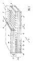
- the detection assembly shown diagrammatically, in perspective and in partial section in FIG. 1 makes it possible to obtain the image of at least one section of an object or of an organ, by detecting the ionizing radiation having passed through this object. or this organ in a section plane.
- the example of X-rays will be taken as ionizing radiation.
- This assembly includes at least one sealed chamber 1 containing an ionizable gas. It is provided with an X-ray transparent entry window 2 coming from the organ or the object. Room 1 and window 2 have not been shown in detail in the figure.
- the interior of the chamber 1 comprises at least one detection stack E1 comprising a plane conductive polarization plate 3, disposed on an insulating support 4 parallel to the cutting plane.
- the stack E1 also includes a series of identical conductive and flat electrodes 5, isolated from each other and arranged on an insulating support 6, parallel to the cutting plane. These electrodes extend in a longitudinal direction directed towards the object; they can be formed for example by depositing copper on the insulating support 6 made of epoxy glass.
- the polarization plate 3 can itself be formed for example by a deposit of copper on the insulating support 4 made of epoxy glass.
- the electrodes 5 are connected by connections 7 to a reference potential (preferably a reference ground) by means of measuring the values of currents flowing in the electrodes and the polarization plate 3 is connected by connection 8 to a DC voltage source, for example positive, not shown in this figure.
- Each stack forms a plurality of detection cells.
- a detection cell is defined by the volume between an electrode and a surface portion of the polarization plate, opposite this electrode.
- the measuring means are themselves connected to means of processing (not shown) which process the measured values to obtain the image of the section of the object or the organ on a display screen.
- the stack E1 also includes an insulating spacer 9 transparent to X-rays, disposed between the polarization plate 3 and the electrodes 5.
- This insulating spacer has the shape of a frame.
- Each detection cell is defined by its pitch p which is substantially equal to the width of the electrode in a plane perpendicular to the longitudinal direction of this electrode. This cell is also defined by its height e which is equal to the distance separating the electrode from the polarization plate 3.
- a stack E2 similar to the stack E1 and comprising electrodes 10 disposed on another face of the insulating support 6, a polarization plate 11 deposited on an insulating support 12, and an insulating spacer 13.
- the spacer part of each stack, located opposite window 2 advantageously comprises at least one plate opaque to X-rays, intermediate plane, parallel to the cutting plane.
- This opaque plate may for example be a copper plate 14 inserted in the spacer 9.
- An intermediate plate 15 is also inserted in the spacer 13 of the stack E2. This intermediate plate makes it possible, as will be seen below in detail, to remove the artefacts for angles of inclination greater than or equal to arctg (d / 2p).
- FIG. 2 provides a better understanding of the disturbances in the ionization of the gas due to the electrodes and to the polarization plate.
- This figure represents a diagram F which gives the variations in the amplitude A of the current which can be collected on each electrode, as a function of the distance D at which the ionization of the gas occurs, relative to the electrode considered. and to the polarization plate, in each of the stacks E1, E2. These stacks are shown schematically and in perspective in the figure, to facilitate understanding.
- the function represented by diagram F can be described as a transverse sensitivity function of the detection assembly.
- the sensitivity or amplitude A of the current supplied by an electrode 5 or 10 increases when the ionization occurs at a distance from the electrode or the corresponding polarization plate (3 or 11). This amplitude decreases when the ionization occurs in the vicinity of each electrode or of each polarization plate. It is zero when ionization occurs on an electrode or on a polarization plate.
- FIG. 3 provides a better understanding of the choice made, according to the invention, in the spacing e between the polarization plate 3 and the measurement electrodes 5 of a detection stack, in relation to the pitch p of each detection cell this choice makes it possible to avoid the appearance of artefacts in the image of a cross-section of an object or an organ, when the latter has inclusions of linear or quasi-linear projections strongly inclined relative to to the cutting plane.
- a straight line I the projection of a plane passing through a plane or quasi-plane inclusion contained in an object, this plane being assumed to be perpendicular to the face front of the detector, itself perpendicular to the cutting plane.
- the straight line I is in fact the projection on the plane perpendicular to the cutting plane and perpendicular to the longitudinal direction of the electrodes, of the inclusion contained in the object or the organ to be studied.
- the angle of the straight line I is designated by ⁇ relative to the plane of the electrodes 5, that is to say relative to the section plane.
- Each crossing by line I of a disturbing element of the stack corresponds to a defect in the image.
- the disturbing elements correspond for example only to those associated with the electrodes 5 and with the polarization plate 3
- the image of the plane or almost plane inclusion corresponding has two faults which are the artifacts respectively due to an electrode and to the polarization plate.
- These defects are reflected for example in the case of a blade, by lines and in the case of a tube, by narrowing.
- the spacing P between the projections on a plane parallel to the cutting plane, of the intersections of the line I with the electrodes and the polarization plate is equal to e / tg ⁇ .
- the number of step detection cells p which participate in the formation of the inclusion image, for the stack considered is equal to n, so that P is close to np
- a single intermediate plate 14 (see FIG. 1) is arranged midway between the electrodes 5 and the polarization plate 3.
- a single intermediate plate 14 is also shown in broken lines in FIG. 3 .
- FIG. 4 provides a better understanding of the importance of choosing a very small thickness of the electrodes and of the polarization plates in the detection assembly.
- This figure represents the transverse sensitivity function of two detection stacks, for which it is assumed that the electrodes, the polarization plates and the supports on which they are arranged have an almost zero thickness.
- the amplitude A of the transverse function F varies between a plateau of maximum amplitude A1 and a minimum M of amplitude A2.
- the transverse function as represented by the dashed lines F1, F2 has a minimum of zero amplitude.
- the thicker the electrodes or the polarization plate the greater the disturbances of the transverse function; this results in important artifacts in the image of a section of an object. It is therefore essential to choose the thicknesses of electrodes, polarization plates and supports for these electrodes and plates, as small as possible. Experience shows that this thickness can be close to the distance B. This distance is in fact the distance which separates the portions F3, F4, of the transverse function F in the vicinity of electrodes or polarization plates of almost zero thickness. , for an amplitude (A1-A2) / 2, close to half the difference in amplitude between the level A1 of the transverse function and the minimum A2 of this function.
- the thickness of the electrodes, of the polarization plates and of the insulating supports of these electrodes and of these plates will be close to a few tenths of a millimeter.
- the insulating supports are advantageously made of epoxy glass while the polarization plates and the electrodes are formed by copper deposits on these insulating supports, for example according to printed circuit techniques.
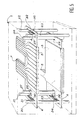
- FIG. 5 shows schematically and in perspective a detection stack according to the invention, inside the ionization chamber 1.
- the same elements have the same references in this figure and in FIG. not shown in this figure the insulating spacer and the intermediate plate.
- the electrodes 5 and the polarization plate 3 are constituted respectively by copper deposits on flexible insulating supports 6, 4 of epoxy glass. Also shown in this figure are connection strips, such as 7 and 8, electrodes and the polarization plate with voltage sources and measurement means external to the enclosure 1.
- the electrodes and the polarization plate as well as their respective supports are very thin. Obtaining a good image quality of a section requires rigorous flatness of the electrode and polarization plate supports.
- means are provided inside the ionization chamber 1 for tensioning the supports 6, 4 parallel to the cutting plane.
- An elastic blade 33 causes the support 4 to be pulled by bearing on the pins 20, 21 and on the tongue 34. It is not necessary, for the support 4 of the plate 3, to pull opposite to the using pins 22, 23 so that the centering pin 28 which passes through the lumen 29 of the support 4, also serves as a pin for holding this position in position.
- the support 6 makes it possible to center the electrodes in the detection assembly. This centering being useless for the polarization plate, the support 4 can be positioned as well by a simple pull as by a double pull of the type of that of the support 6.
Landscapes
- Physics & Mathematics (AREA)
- Health & Medical Sciences (AREA)
- Life Sciences & Earth Sciences (AREA)
- General Physics & Mathematics (AREA)
- High Energy & Nuclear Physics (AREA)
- Molecular Biology (AREA)
- Spectroscopy & Molecular Physics (AREA)
- Measurement Of Radiation (AREA)
- Apparatus For Radiation Diagnosis (AREA)
Applications Claiming Priority (2)
| Application Number | Priority Date | Filing Date | Title |
|---|---|---|---|
| FR8803796 | 1988-03-23 | ||
| FR8803796A FR2629215B1 (fr) | 1988-03-23 | 1988-03-23 | Ensemble de detection pour tomographie a rayonnements ionisants |
Publications (1)
| Publication Number | Publication Date |
|---|---|
| EP0334750A1 true EP0334750A1 (de) | 1989-09-27 |
Family
ID=9364562
Family Applications (1)
| Application Number | Title | Priority Date | Filing Date |
|---|---|---|---|
| EP89400792A Withdrawn EP0334750A1 (de) | 1988-03-23 | 1989-03-21 | Detektoranordnung für die Tomographie mittels ionisierender Strahlungen |
Country Status (4)
| Country | Link |
|---|---|
| US (1) | US5018175A (de) |
| EP (1) | EP0334750A1 (de) |
| JP (1) | JPH01297583A (de) |
| FR (1) | FR2629215B1 (de) |
Families Citing this family (1)
| Publication number | Priority date | Publication date | Assignee | Title |
|---|---|---|---|---|
| US10444381B2 (en) * | 2015-12-03 | 2019-10-15 | Koninklijke Philips N.V. | Radiation detector and imaging apparatus |
Citations (3)
| Publication number | Priority date | Publication date | Assignee | Title |
|---|---|---|---|---|
| US4047039A (en) * | 1976-06-03 | 1977-09-06 | General Electric Company | Two-dimensional x-ray detector array |
| EP0063083A1 (de) * | 1981-04-15 | 1982-10-20 | Commissariat à l'Energie Atomique | Röntgenstrahlungsdetektor |
| US4559639A (en) * | 1982-11-22 | 1985-12-17 | General Electric Company | X-Ray detector with compensation for height-dependent sensitivity and method of using same |
-
1988
- 1988-03-23 FR FR8803796A patent/FR2629215B1/fr not_active Expired - Lifetime
-
1989
- 1989-03-15 US US07/323,885 patent/US5018175A/en not_active Expired - Fee Related
- 1989-03-21 EP EP89400792A patent/EP0334750A1/de not_active Withdrawn
- 1989-03-23 JP JP1069409A patent/JPH01297583A/ja active Pending
Patent Citations (3)
| Publication number | Priority date | Publication date | Assignee | Title |
|---|---|---|---|---|
| US4047039A (en) * | 1976-06-03 | 1977-09-06 | General Electric Company | Two-dimensional x-ray detector array |
| EP0063083A1 (de) * | 1981-04-15 | 1982-10-20 | Commissariat à l'Energie Atomique | Röntgenstrahlungsdetektor |
| US4559639A (en) * | 1982-11-22 | 1985-12-17 | General Electric Company | X-Ray detector with compensation for height-dependent sensitivity and method of using same |
Also Published As
| Publication number | Publication date |
|---|---|
| FR2629215A1 (fr) | 1989-09-29 |
| JPH01297583A (ja) | 1989-11-30 |
| US5018175A (en) | 1991-05-21 |
| FR2629215B1 (fr) | 1990-11-16 |
Similar Documents
| Publication | Publication Date | Title |
|---|---|---|
| EP0678896B1 (de) | Medizinischer Bilderzeugungsvorrichtung mittels ionisierender Röntgen- oder Gamma Strahlungen niedriger Dosis | |
| WO1996017373A1 (fr) | Detecteur de rayonnements ionisants a microcompteurs proportionnels | |
| EP0730291B1 (de) | Vorrichtung zur Erzeugung medizinischer Bilder mittels ionisierender Röntgen- oder niederdosis Gammastrahlen | |
| EP1869500B1 (de) | Vorrichtung zum begrenzen des auftretens von dekodierungsartefakten für eine gammakamera mit kodierter maske | |
| EP0810631A1 (de) | Röntgenbilderzeugungsvorrichtung hoher Auflösung | |
| Wiersma et al. | An accurate technique to record the angular distribution of backscattered light | |
| FR2668612A1 (fr) | Dispositif d'imagerie de radiations ionisantes. | |
| EP0014609A1 (de) | Vorrichtung zur Bilddarstellung auf einem grossen Bildschirm | |
| EP0228933A1 (de) | Vorrichtung zur Wahrnehmung und Lokalisierung von neutralen Partikeln und deren Anwendung | |
| FR2526575A1 (fr) | Procede de traitement d'image radiologique en vue de corriger ladite image des defauts dus au rayonnement diffuse | |
| EP0064913A2 (de) | Mehrelementenröntgendetektor | |
| EP0046125A2 (de) | Strahlungsdetektor | |
| EP0334750A1 (de) | Detektoranordnung für die Tomographie mittels ionisierender Strahlungen | |
| EP0063082A1 (de) | Röntgenstrahlungsdetektor | |
| EP0063083B1 (de) | Röntgenstrahlungsdetektor | |
| EP0368694A1 (de) | Verfahren und Vorrichtung zur hochauflösenden Lokalisierung von neutralen Partikeln | |
| Thiébaut | Speckle interferometry with a photon-counting detector | |
| EP0326479B1 (de) | Röntgenstrahlungsdetektor für Tomographie | |
| EP0267104B1 (de) | Video-Mischerschaltung für Hochauflösungsabbildung mit matrixförmigen Festkörpersensorenkameras | |
| EP0764855B1 (de) | Verfahren zur Erzeugung eines Nuklearmedizin-Körperbildes mit Abstumpfungskorrektur | |
| EP0001523A1 (de) | Verfahren und Einrichtung für axiale transversale Tomographie | |
| EP3749981B1 (de) | System zur charakterisierung eines strahls geladener teilchen und maschine zur erzeugung eines strahls geladener teilchen mit einem solchen system | |
| FR2522415A1 (fr) | Detecteur proportionnel de rayonnements ionisants pour localisation a deux dimensions | |
| FR2488995A1 (fr) | Dispositif d'examen au moyen d'un rayonnement disperse pour la determination de structures internes d'un corps | |
| FR2630829A1 (fr) | Detecteur gazeux pour rayons-x sans parallaxe |
Legal Events
| Date | Code | Title | Description |
|---|---|---|---|
| PUAI | Public reference made under article 153(3) epc to a published international application that has entered the european phase |
Free format text: ORIGINAL CODE: 0009012 |
|
| AK | Designated contracting states |
Kind code of ref document: A1 Designated state(s): DE GB NL |
|
| 17P | Request for examination filed |
Effective date: 19900303 |
|
| 17Q | First examination report despatched |
Effective date: 19920728 |
|
| STAA | Information on the status of an ep patent application or granted ep patent |
Free format text: STATUS: THE APPLICATION IS DEEMED TO BE WITHDRAWN |
|
| 18D | Application deemed to be withdrawn |
Effective date: 19930914 |