EP0334266B2 - Apparatus for closing containers with a sealing lamina - Google Patents
Apparatus for closing containers with a sealing lamina Download PDFInfo
- Publication number
- EP0334266B2 EP0334266B2 EP89104968A EP89104968A EP0334266B2 EP 0334266 B2 EP0334266 B2 EP 0334266B2 EP 89104968 A EP89104968 A EP 89104968A EP 89104968 A EP89104968 A EP 89104968A EP 0334266 B2 EP0334266 B2 EP 0334266B2
- Authority
- EP
- European Patent Office
- Prior art keywords
- pusher
- containers
- actuation
- framework
- conveyor belt
- Prior art date
- Legal status (The legal status is an assumption and is not a legal conclusion. Google has not performed a legal analysis and makes no representation as to the accuracy of the status listed.)
- Expired - Lifetime
Links
Images


Classifications
-
- B—PERFORMING OPERATIONS; TRANSPORTING
- B65—CONVEYING; PACKING; STORING; HANDLING THIN OR FILAMENTARY MATERIAL
- B65B—MACHINES, APPARATUS OR DEVICES FOR, OR METHODS OF, PACKAGING ARTICLES OR MATERIALS; UNPACKING
- B65B7/00—Closing containers or receptacles after filling
- B65B7/16—Closing semi-rigid or rigid containers or receptacles not deformed by, or not taking-up shape of, contents, e.g. boxes or cartons
- B65B7/162—Closing semi-rigid or rigid containers or receptacles not deformed by, or not taking-up shape of, contents, e.g. boxes or cartons by feeding web material to securing means
- B65B7/164—Securing by heat-sealing
Definitions
- the present invention relates to a device for closing containers with a sealing lamina.
- Said containers have a sharp edge along the periphery of their rim and a planar region which is arranged further inwardly and has a limited width.
- the thin lamina of interposed material is cut at the sharp edges and is heat-welded at the planar regions of the rims.
- the containers are conveyed by means of a continuous conveyor belt on supporting tables or grids which are arranged manually below the head, from which they are removed with the same manual method.
- An automatic machine for sealing containers showing the features recited in the precharacterizing part of claim 1, and inlet and outlet fixed guides, is disclosed by the machines XL3.3/3.4 manufactured by Alcan Kunststoff GmbH of Göttingen, Germany.
- the aim of the present invention is to eliminate the above described disadvantages by providing an apparatus for closing containers by heat-welding lids obtained from a lamina, which allows continuous-cycle processing.
- a particular object is to completely automate the transfer of the containers among the various parts of the apparatus.
- a further object of the invention is to provide an apparatus which has reduced dimensions though it allows high speed in its production cycle.
- a not least object of the present invention is to provide an apparatus which is capable of giving the greatest assurances of reliability and safety in use by virtue of its peculiar constructive characteristics.
- the apparatus comprises a framework 2 which supports a first conveyor belt 3 for feeding containers which are to be closed, a heat-welding unit formed by a resting table 4 above which a welding head 6 is arranged and a second conveyor belt 5 for removing the closed containers.
- the first conveyor belt 3 is of the intermittent type to allow a certain number of containers to wait ahead of the heat-welding unit for the time required to transfer them onto the resting table.
- a continuous conveyor belt (not illustrated in figure 1) may be arranged ahead of said first conveyor belt 3; and its end portion 7 adjacent to the conveyor belt 3 has been schematically illustrated in figures 2 to 4.
- the resting table 4 is initially at the same level as the conveyor belts 3 and 5.
- the apparatus according to the invention advantageously comprises a pusher which is arranged laterally on said frame in a region adjacent to the table 4 and to the belts 3 and 5.
- said pusher comprises a first pusher element and a second pusher element, equal to one another or opposite with respect to the table and to the conveyor belts so as to engage the containers on opposite sides.
- the pusher 8 is formed by a grip region 9 having protrusions 10 adapted to engage with a plurality of containers C and connected by means of an intermediate portion 11 to a sleeve-like coupling portion 12.
- the grip portion 9 is conveniently substantially twice as long as the table.
- the shape of the protrusions 1 is extremely simple, since it adapts to lateral protrusions provided on the containers.
- a single lateral pusher element with more complicated grip elements, such as brackets may be provided so as to laterally and rearwardly engage the containers, which may possibly be supported on the opposite side with respect to the pusher by a longitudinal guide.
- a shaft 13 is used to actuate in practice the oscillatory and longitudinal translatory movements of the pusher 8; said shaft is mounted freely rotatable and slidable in a support 14 rigidly associated with the framework 2, in such a position that its axis is parallel to the direction of unwinding of the belts 3 and 5.
- the coupling portion 12 is fixed to one end of the shaft 13 and supports the intermediate portion 11 and the grip portion 9 so that the latter extends in a direction which is parallel to the shaft 13.
- An end sleeve 15 is fixed to the end of the shaft 13 which is opposite to the coupling portion 12; said sleeve supports a pusher bush 16 which is free to rotate but not to shift with respect to the sleeve 15.
- Said sleeve is internally provided with a longitudinal groove 17 which extends parallel to the axis of the shaft 13.
- Actuation means advantageously act on the pusher to make it oscillate about its axis of rotation from a first engagement position to a second disengagement position relatively to the plurality of containers.
- a torsion shaft 18 is supported coaxially to the actuation shaft 13 and has a longitudinal protrusion 19 engageable with the inner groove 17 of the end sleeve 15. Said shaft 18 is inserted in the sleeve 15 and extends within the shaft 13. In this manner, while the torsion shaft 18 transmits a rotation to the actuation shaft 13, the latter can slide freely along its axis by virtue of the groove provided inside the sleeve 15 as indicated in figure 5 by the arrows F1 and F2.
- a crank 20 is keyed to the free end of the torsion shaft 18 and is connected by means of a tension element 21 to an L-shaped lever 22 pivoted at 22a on the supporting framework 2.
- a roller 23 is pivoted on the other end of the L-shaped lever 22 and is slidably guided in a circular groove 24 provided on a cam defined beforehand in a wheel 25.
- Said wheel 25 and said cam path 24 constitute, as a whole, the first guiding means, and are actuated by a first motor reducer assembly 26.
- Second actuation means are advantageously provided and act on the pusher to move it longitudinally along its axis of rotation.
- the pivot 27 fixed to the bush 16 is connected by means of an articulating rod, not illustrated, to the end 28 of a first lever 29 of an articulated quadrilateral; said first lever is pivoted at 29a, and a second follower roller 31 is pivoted on the second lever 30 of said articulated quadrilateral; said second lever is pivoted at 30a.
- Said roller 31 is guided within a circular groove 32 defined on a cam provided beforehand in a second actuation wheel 33 which is rotatably mounted on the framework 2 and is actuated by a second motor reducer assembly 34.
- the table 4 is mounted on a slider 35 formed by columns 36 which can slide vertically in supports 37 rigidly associated with the supporting framework and are downwardly connected to a plate 38.
- Third actuation means conveniently act on the table 4 to move it vertically towards and/or away from the heat-welding head 6, as indicated by the arrow F3.
- Said third actuation means comprise a hydraulic or pneumatic piston which has the function of automatically adjusting the specific welding pressure, which can be preset for any kind and thickness of sealing lamina.
- the length of said piston 39 can be adjusted by means of screws and internal or female threads 40; said piston is connected to one end of an L-shaped lever 41 which is pivoted at 42 in the framework and has a follower roller 43 at the other end.
- Said roller is guided by a guiding groove 44 defined in a third actuation wheel 45 actuated by third motor means 46.
- the wheel 45 and the groove 44 constitute, as a whole, the third guiding means.
- Synchronization means are provided in order to mutually synchronize the movements of the three actuation means and are schematically indicated in figure 7 by the reference numeral 47; said means substantially consist of cam assemblies associated with electric switches for actuating motor reducer units which respectively actuate the actuation wheels 23, 33 and 45.
- rollers 48 and 49 are provided at the input and at the output of the heat-welding head and support a band of laminar material 50.
- the pusher 8 is shown in top view in a first terminal position in which the grip portions 9 are engaged with the containers, with their leading half arranged facing the table 4 and with their trailing half arranged facing the conveyor belt 3.
- Figure 4 illustrates the pushers just before they resume their cycle of transfer from their first longitudinal position, in which the grip portions are engaged with the containers, toward their second longitudinal terminal position.
- the operation of the device according to the invention is evident.
- the first and second actuation means are synchronized so as to provide movement from the first longitudinal position to the second one while the grip portions are engaged with the containers.
- the third actuation means are synchronized so as to keep the table 4 at the same level as the conveyor belts 3 and 5.
- the third actuation means are synchronized so as to cause the table 4 to move towards and subsequently away from the heat-welding head 6.
- the table is at the same level as the conveyor belts 3 and 5 and can thus start a new work cycle.
- the apparatus according to the invention fully achieves the aim of automating the process of heat-welding containers and of making it continuous with a high operating speed, while allowing to contain the dimensions of the apparatus in the direction parallel to the extension of the belts.
- the materials employed may be any according to the requirements and to the state of the art.
Description
- The present invention relates to a device for closing containers with a sealing lamina.
- As is known, in order to perform the process of closing by heat-welding, it is necessary to arrange a plurality of containers below the head of a sealing unit; said containers are subsequently compressed against the opposite surface of said head with the interposition of a film of heat-weldable material such as aluminum or plastic.
- Said containers have a sharp edge along the periphery of their rim and a planar region which is arranged further inwardly and has a limited width.
- Due to the pressure exerted on the containers, the thin lamina of interposed material is cut at the sharp edges and is heat-welded at the planar regions of the rims.
- In practice the containers are conveyed by means of a continuous conveyor belt on supporting tables or grids which are arranged manually below the head, from which they are removed with the same manual method.
- Even with the use of conveyor belts for feeding and removal, the process does not allow high speeds, since it is discontinuous and not automated.
- Another disadvantage resides in the fact that heads of considerable dimensions are used in order to increase the number of containers treated simultaneously, with consequent higher manufacturing and operating costs for the apparatus.
- An automatic machine for sealing containers, showing the features recited in the precharacterizing part of
claim 1, and inlet and outlet fixed guides, is disclosed by the machines XL3.3/3.4 manufactured by Alcan Deutschland GmbH of Göttingen, Germany. - The aim of the present invention is to eliminate the above described disadvantages by providing an apparatus for closing containers by heat-welding lids obtained from a lamina, which allows continuous-cycle processing.
- Within the scope of this aim, a particular object is to completely automate the transfer of the containers among the various parts of the apparatus.
- A further object of the invention is to provide an apparatus which has reduced dimensions though it allows high speed in its production cycle.
- A not least object of the present invention is to provide an apparatus which is capable of giving the greatest assurances of reliability and safety in use by virtue of its peculiar constructive characteristics.
- This aim, as well as these and other objects which will become apparent hereinafter, are achieved by an apparatus for closing containers with a sealing lamina as defined in
claim 1. - Further advantages of the invention will become apparent from the description of a preferred but not exclusive embodiment of the device according to the invention, illustrated only by way of non-limitative example in the accompanying drawings, wherein:
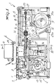
- figure 1 is a partially sectional lateral elevational view of the apparatus according to the invention, with some parts illustrated schematically;
- figures 2 to 4 are schematic top plan views of a detail of the apparatus according to the invention in three successive operating steps, wherein the head has been removed for the sake of clarity;
- figure 5 is a perspective view of a detail of the apparatus, illustrating the pusher element, wherein some parts have been removed for the sake of clarity;
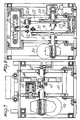
- figure 6 is a partially sectional lateral elevational view of a part of the apparatus according to the invention;
- figure 7 is a first partially sectional front elevational view of the apparatus according to the invention;
- figure 8 is a second partially sectional front elevational view of the apparatus according to the invention;
- figure 9 is a sectional view taken along the line IX-IX of figure 1.
- With reference to the above described figures, the apparatus according to the invention, generally indicated by the
reference numeral 1, comprises aframework 2 which supports afirst conveyor belt 3 for feeding containers which are to be closed, a heat-welding unit formed by a resting table 4 above which awelding head 6 is arranged and asecond conveyor belt 5 for removing the closed containers. - In particular, the
first conveyor belt 3 is of the intermittent type to allow a certain number of containers to wait ahead of the heat-welding unit for the time required to transfer them onto the resting table. A continuous conveyor belt (not illustrated in figure 1) may be arranged ahead of saidfirst conveyor belt 3; and itsend portion 7 adjacent to theconveyor belt 3 has been schematically illustrated in figures 2 to 4. - It should be furthermore noted that the resting table 4 is initially at the same level as the
conveyor belts - The apparatus according to the invention advantageously comprises a pusher which is arranged laterally on said frame in a region adjacent to the table 4 and to the
belts pusher 8 is formed by agrip region 9 havingprotrusions 10 adapted to engage with a plurality of containers C and connected by means of anintermediate portion 11 to a sleeve-like coupling portion 12. Thegrip portion 9 is conveniently substantially twice as long as the table. In the illustrated case the shape of theprotrusions 1 is extremely simple, since it adapts to lateral protrusions provided on the containers. In alternative embodiments, however, a single lateral pusher element with more complicated grip elements, such as brackets, may be provided so as to laterally and rearwardly engage the containers, which may possibly be supported on the opposite side with respect to the pusher by a longitudinal guide. - A
shaft 13 is used to actuate in practice the oscillatory and longitudinal translatory movements of thepusher 8; said shaft is mounted freely rotatable and slidable in asupport 14 rigidly associated with theframework 2, in such a position that its axis is parallel to the direction of unwinding of thebelts coupling portion 12 is fixed to one end of theshaft 13 and supports theintermediate portion 11 and thegrip portion 9 so that the latter extends in a direction which is parallel to theshaft 13. Anend sleeve 15 is fixed to the end of theshaft 13 which is opposite to thecoupling portion 12; said sleeve supports apusher bush 16 which is free to rotate but not to shift with respect to thesleeve 15. Said sleeve is internally provided with alongitudinal groove 17 which extends parallel to the axis of theshaft 13. - Actuation means advantageously act on the pusher to make it oscillate about its axis of rotation from a first engagement position to a second disengagement position relatively to the plurality of containers.
- In particular, a
torsion shaft 18 is supported coaxially to theactuation shaft 13 and has alongitudinal protrusion 19 engageable with theinner groove 17 of theend sleeve 15. Saidshaft 18 is inserted in thesleeve 15 and extends within theshaft 13. In this manner, while thetorsion shaft 18 transmits a rotation to theactuation shaft 13, the latter can slide freely along its axis by virtue of the groove provided inside thesleeve 15 as indicated in figure 5 by the arrows F1 and F2. - A
crank 20 is keyed to the free end of thetorsion shaft 18 and is connected by means of atension element 21 to an L-shaped lever 22 pivoted at 22a on the supportingframework 2. Aroller 23 is pivoted on the other end of the L-shaped lever 22 and is slidably guided in acircular groove 24 provided on a cam defined beforehand in awheel 25. - Said
wheel 25 and saidcam path 24 constitute, as a whole, the first guiding means, and are actuated by a firstmotor reducer assembly 26. - Second actuation means are advantageously provided and act on the pusher to move it longitudinally along its axis of rotation.
- In particular, the
pivot 27 fixed to thebush 16 is connected by means of an articulating rod, not illustrated, to theend 28 of afirst lever 29 of an articulated quadrilateral; said first lever is pivoted at 29a, and asecond follower roller 31 is pivoted on thesecond lever 30 of said articulated quadrilateral; said second lever is pivoted at 30a. Saidroller 31 is guided within acircular groove 32 defined on a cam provided beforehand in asecond actuation wheel 33 which is rotatably mounted on theframework 2 and is actuated by a secondmotor reducer assembly 34. - According to the invention, the table 4 is mounted on a slider 35 formed by
columns 36 which can slide vertically insupports 37 rigidly associated with the supporting framework and are downwardly connected to aplate 38. - Third actuation means conveniently act on the table 4 to move it vertically towards and/or away from the heat-
welding head 6, as indicated by the arrow F3. Said third actuation means comprise a hydraulic or pneumatic piston which has the function of automatically adjusting the specific welding pressure, which can be preset for any kind and thickness of sealing lamina. The length of saidpiston 39 can be adjusted by means of screws and internal orfemale threads 40; said piston is connected to one end of an L-shaped lever 41 which is pivoted at 42 in the framework and has afollower roller 43 at the other end. Said roller is guided by a guidinggroove 44 defined in athird actuation wheel 45 actuated by third motor means 46. Thewheel 45 and thegroove 44 constitute, as a whole, the third guiding means. - Synchronization means are provided in order to mutually synchronize the movements of the three actuation means and are schematically indicated in figure 7 by the reference numeral 47; said means substantially consist of cam assemblies associated with electric switches for actuating motor reducer units which respectively actuate the
actuation wheels - For the sake of completeness of the description, two
rollers laminar material 50. - The operation of the pusher element can be understood more clearly with reference to figures 2, 3 and 4.
- With reference to figure 2, the
pusher 8 is shown in top view in a first terminal position in which thegrip portions 9 are engaged with the containers, with their leading half arranged facing the table 4 and with their trailing half arranged facing theconveyor belt 3. - The rightward movement of the
actuation shafts 13 causes the advancement of the pair of pushers to a second terminal position in which thegrip portions 9 have their trailing half arranged facing the table 4 and their leading half arranged facing theconveyor belt 5. This condition is illustrated in figure 3, wherein the two pusher elements are disengaged from the containers due to their opposite rotation provided by means of theactuation shafts 13. - The pushers return toward their first terminal position with the grip portions open, i.e. not engaged with the containers, as shown in broken lines in figure 3. Figure 4 illustrates the pushers just before they resume their cycle of transfer from their first longitudinal position, in which the grip portions are engaged with the containers, toward their second longitudinal terminal position.
- After what has been described, the operation of the device according to the invention is evident. In order to transfer the containers from the
conveyor belt 3 to the resting table 4, the first and second actuation means are synchronized so as to provide movement from the first longitudinal position to the second one while the grip portions are engaged with the containers. During this step the third actuation means are synchronized so as to keep the table 4 at the same level as theconveyor belts welding head 6. When the table is in its uppermost position the containers resting thereon are pushed against thelamina 50, which is cut and welded onto said containers. - When the pushers are returned to their first terminal position with the grip portions open, the table is at the same level as the
conveyor belts - In practice it has been observed that the apparatus according to the invention fully achieves the aim of automating the process of heat-welding containers and of making it continuous with a high operating speed, while allowing to contain the dimensions of the apparatus in the direction parallel to the extension of the belts.
- In practice, the materials employed, so long as compatible with the specified use, as well as the dimensions, may be any according to the requirements and to the state of the art.
Claims (16)
- An automatic apparatus for closing containers (c) with a sealing lamina (50), the containers (c) being fed to the apparatus by a feeding conveyor (7), the apparatus comprising a framework (2) supporting a sealing unit (4, 6) including a heat-welding head (6) arranged above a resting table (4), a second conveyor belt (5) leading away from an outlet side of said sealing unit (4, 6), a pusher (8) defining a grip portion (9) which is engageable with a plurality of containers (c) to be transferred towards and away from said sealing unit (4, 6), first actuation means (18-20, 22, 26) acting on said pusher (8) to engage it with said plurality of containers (c) and disengage it therefrom and second actuation means (28-33) to move said pusher (8) longitudinally along its axis of rotation, arranged between said feeding conveyor (7) and said sealing unit (4, 6), a first conveyor belt (3) leading from said feeding conveyor belt (7) towards an inlet side of said sealing unit (4, 6), said sealing unit (4, 6) has a longitudinal size for sealing at least one container at a time,
characterized in that- said first conveyor belt (3) is of the intermittent type and is operatively connected to said sealing unit (4, 6) to allow a number of containers to wait ahead of the sealing unit (4, 6) for the time required to transfer them onto said resting table (4) thereof,- said pusher (8) moves from a first position in which said grip portion (9) is arranged to flank a leading portion of said first conveyor belt (3) and said resting table (4) to a second position in which said grip portion (9) is arranged to flank a trailing portion of said second conveyor belt (5) and said resting table (4),- said grip portion (9) overlapping the conveyor belts (3) and (5) at the leading/trailing portion respectively for a length corresponding to the length of at least one container to be processed, - said second conveyor belt (5) being operatively connected to said sealing unit (4, 6). - Apparatus according to claim 1, characterized in that said grip portion (9) extends in a direction which is substantially parallel to the direction of advancement of the containers (c) with a useful length which is substantially twice that of said table (4) in order to simultaneously load and unload an equal number of containers on said table as said pusher (8) passes from said first longitudinal position to said second position.
- Apparatus according to one or more of the preceding claims, characterized in that said grip portion (9) is arranged facing said table (4) with its leading half when said pusher (8) is in said first longitudinal position and with its trailing half when said pusher (8) is in said second longitudinal position.
- Apparatus according to claim 1, characterized in that said table (4) is mounted so as to be vertically movable on said framework (2), third actuation means (39-46) acting on said table (4) to move it vertically from a first elevation, at which it is substantially at the same level as said belts (3, 5), to a second level, at which it is substantially at the level of said head (6) with said lamina (50) and said containers (c) interposed.
- Apparatus according to one or more of the preceding claims, characterized in that it comprises first means (47) for mutually synchronizing said first (18-20, 22, 26) and second (28-33) actuation means, for keeping said pusher (8) in engagement position relatively to said plurality of containers (c) during its passage from said first position to said second position and for keeping said pusher (8) in its release position with respect to said plurality of containers (c) in its reverse passage from said second position to said first position.
- Apparatus according to one or more of the preceding claims, characterized in that it comprises second means (47) for mutually synchronizing said second (28-33) and said third (39-46) actuation means, for keeping said table (4) at said first elevation while said pusher (8) moves from said first position to said second one and for moving said table (4) towards said head (6) and away therefrom during the reverse passage of said pusher (8) from said second position to said first position.
- Apparatus according to one or more of the preceding claims, characterized in that said pusher (8) comprises an intermediate portion (11) for connecting said grip portion (9) and a coupling portion (12) rigidly fixed to one end of an actuation shaft (13) which is rotatably and slidably supported on said framework (2) with its axis parallel to said direction of advancement of the containers (c).
- Apparatus according to one or more of the preceding claims, characterized in that said actuation shaft (13) is internally hollow and has a terminal sleeve (15) at its end opposite to said coupling portion (12), said sleeve (15) being internally provided with a longitudinal groove (17) and supporting a pusher bush (16) which is free to rotate about said sleeve (15) and is longitudinally locked thereon.
- Apparatus according to one or more of the preceding claims, characterized in that said first actuation means (18-20, 22, 26) comprise first guiding means (24, 25) for a first follower roller (23), said first roller being pivoted at one end of first connection means (22) interposed between said first guiding means (24, 25) and said actuation shaft (13), said first connection means (22) comprising an L-shaped lever which is pivoted with its middle portion on said framework (2) and is connected to a crank (20) keyed to one end of a torsion shaft (18), said torsion shaft having, at its other end, a longitudinal protrusion (19) which slidably engages said inner groove (17) of said terminal sleeve (15).
- Apparatus according to one or more of the preceding claims, characterized in that said second actuation means (28-33) comprise second guiding means (32) for a second follower roller (31), said second follower roller (31) being pivoted to an end of second connecting means (30) interposed between said second guiding means (32) and said actuation shaft (13), said second connecting means (30) comprising an articulated quadrilateral pivoted to said framework (2) and connected to said pusher bush (16) with an interposed articulation rod.
- Apparatus according to one or more of the preceding claims, characterized in that said third actuation means (39-46) comprise third guiding means (44, 45) for a third follower roller (43), said third follower roller (43) being pivoted to one end of third connecting means (41) interposed between said third guiding means (44, 45) and a slider (35) which is vertically slidable on said framework (2) which supports said resting table (4), said third connecting means (41) being constituted by an L-shaped lever (41) which is pivoted in said framework (2) and is connected to said slider (35) with an interposed rod-like element.
- Apparatus according to one or more of the preceding claims, characterized in that said rod-like element is constituted by a hydraulic or pneumatic piston (39) which has the function of adjusting the specific welding pressure acting on said table (4).
- Apparatus according to one or more of the preceding claims, characterized in that each of said first, second and third guiding means comprises a circular path on a cam (24, 32, 44) in a respective actuation wheel (25, 33, 45) associated with said framework (2) and actuated by respective motor means (26, 34, 46), said path being slidably coupled respectively to said first, second and third follower roller.
- Apparatus according to one or more of the preceding claims, characterized in that said pusher (8) comprises a first and a second pusher element which are identical to one another and are opposite with respect to said table (4) and to said belts (3, 5).
- Apparatus according to one or more of the preceding claims, characterized in that said pusher (8) comprises a single lateral pusher element provided with grip elements so as to laterally and rearwardly engage the containers (c).
- Apparatus according to one or more of the preceding claims, characterized in that said first conveyor belt (3) is of the intermittent type, with an interruption of its motion when said grip portion (9) partially faces said first belt (3).
Applications Claiming Priority (2)
| Application Number | Priority Date | Filing Date | Title |
|---|---|---|---|
| IT8819934A IT1216515B (en) | 1988-03-24 | 1988-03-24 | EQUIPMENT FOR CLOSING CONTAINERS WITH SEALING PLATE. |
| IT1993488 | 1988-03-24 |
Publications (3)
| Publication Number | Publication Date |
|---|---|
| EP0334266A1 EP0334266A1 (en) | 1989-09-27 |
| EP0334266B1 EP0334266B1 (en) | 1992-09-30 |
| EP0334266B2 true EP0334266B2 (en) | 1995-10-25 |
Family
ID=11162465
Family Applications (1)
| Application Number | Title | Priority Date | Filing Date |
|---|---|---|---|
| EP89104968A Expired - Lifetime EP0334266B2 (en) | 1988-03-24 | 1989-03-20 | Apparatus for closing containers with a sealing lamina |
Country Status (5)
| Country | Link |
|---|---|
| US (1) | US4974392A (en) |
| EP (1) | EP0334266B2 (en) |
| DE (1) | DE68903016T2 (en) |
| ES (1) | ES2034449T5 (en) |
| IT (1) | IT1216515B (en) |
Cited By (1)
| Publication number | Priority date | Publication date | Assignee | Title |
|---|---|---|---|---|
| EP2374717A1 (en) | 2010-04-09 | 2011-10-12 | G. MONDINI S.p.A. | Apparatus for sealing trays. |
Families Citing this family (34)
| Publication number | Priority date | Publication date | Assignee | Title |
|---|---|---|---|---|
| JP2568423Y2 (en) * | 1992-03-06 | 1998-04-15 | 四国化工機株式会社 | Container sealing device |
| IT227649Y1 (en) * | 1992-09-30 | 1997-12-15 | Comau Spa | DEVICE FOR THE QUICK CHANGE OF WORKPIECE PALLET IN AN ASSEMBLY MACHINE. |
| IT1269721B (en) * | 1994-05-06 | 1997-04-15 | Mondini G Spa | MACHINE FOR SEALING CONTAINERS THROUGH THE APPLICATION OF A COVERING PLATE |
| US5522200A (en) * | 1995-02-10 | 1996-06-04 | Nestec Machine Systems Ltd. | Continuous motion sealer |
| GB2343536B (en) | 1998-11-06 | 2003-10-08 | Nokia Mobile Phones Ltd | Alerting apparatus |
| SE518494C2 (en) * | 2001-02-09 | 2002-10-15 | Tetra Laval Holdings & Finance | Device and method for extracting individual objects from a series of objects |
| US7089718B2 (en) * | 2002-06-10 | 2006-08-15 | Green-Line Products, Inc. | Apparatus for heat-shrinking film onto an open-topped container and method of using same |
| US20040020171A1 (en) * | 2002-06-10 | 2004-02-05 | Biba Scott I. | Web cutter |
| US6834476B2 (en) * | 2002-10-17 | 2004-12-28 | Ibaraki Seiki Machinery Company, Ltd. | Sealing and packaging device for cover film on tray |
| DE102004023474A1 (en) * | 2004-05-12 | 2005-12-15 | Multivac Sepp Haggenmüller Gmbh & Co. Kg | Packaging machine and method for closing containers |
| US20050274092A1 (en) * | 2004-06-10 | 2005-12-15 | Packaging Technologies, Inc. | Continuous motion sealer |
| ITMI20072058A1 (en) | 2007-10-25 | 2009-04-26 | Mondini Spa G | SYSTEM FOR THE CONTEMPORARY SEALING OF MORE FILES OF CONTAINERS |
| DE102008008678B4 (en) | 2008-02-12 | 2017-02-02 | Multivac Sepp Haggenmüller Se & Co. Kg | Packaging machine and method for closing containers with foil |
| DE102008030510A1 (en) | 2008-06-27 | 2010-01-14 | Multivac Sepp Haggenmüller Gmbh & Co. Kg | Packaging machine with a gripper system |
| DE102008048831A1 (en) | 2008-09-25 | 2010-04-08 | Multivac Sepp Haggenmüller Gmbh & Co. Kg | Conveying device for packaging machine, has buffer conveyor, on which containers are conveyed, and collecting conveyor, through which containers are brought in predetermined distance to each other |
| DE102009004837A1 (en) * | 2009-01-16 | 2010-07-22 | Multivac Sepp Haggenmüller Gmbh & Co. Kg | Multitrack packaging machine |
| IT1396479B1 (en) * | 2009-08-10 | 2012-12-14 | Gruppo Fabbri S P A | MACHINE FOR PACKAGING PRODUCTS IN RIGID OR SEMI-RIGID TRAYS, CLOSED SUPERIOR WITH A THERMOPLASTIC FILM, PARTICULARLY TO PRODUCE MODIFIED ATMOSPHERE PACKAGES. |
| DE102010027211B4 (en) * | 2010-07-15 | 2012-04-26 | Multivac Sepp Haggenmüller Gmbh & Co. Kg | Gripper system for a tray sealing machine |
| DE102010056316B4 (en) * | 2010-12-27 | 2015-07-02 | Multivac Sepp Haggenmüller Gmbh & Co. Kg | Shell sealing machine and method of operating such a tray sealing machine |
| EP2517963B1 (en) * | 2011-04-29 | 2013-10-23 | Multivac Sepp Haggenmüller GmbH & Co. KG | Packaging machine with transport device |
| PL2731892T3 (en) * | 2011-07-11 | 2017-06-30 | Å&R Carton Lund Ab | Apparatus and method for sealing a cardboard based container |
| US8695779B2 (en) | 2011-10-24 | 2014-04-15 | Remedi Technology Holdings, Llc | Packaging system for pharmaceutical dispenser and associated method |
| DE102012007598B4 (en) * | 2012-04-16 | 2022-02-24 | Multivac Sepp Haggenmüller Se & Co. Kg | Pusher unit and method for positioning products on a package carrier |
| ITBO20120353A1 (en) * | 2012-06-26 | 2013-12-27 | Gruppo Fabbri Vignola Spa | APPARATUS FOR THE ORDERED SUPPLY OF TRAYS GROUPS TO A MACHINE USED FOR SEALING THE SHEETS WITH THEIR APPLICATION OF A COVER FILM |
| DE102012015401B4 (en) * | 2012-08-03 | 2019-04-11 | Multivac Sepp Haggenmüller Se & Co. Kg | Tray sealing machine |
| EP2706012B1 (en) * | 2012-09-10 | 2014-11-05 | MULTIVAC Sepp Haggenmüller GmbH & Co KG | Jacket closing machine |
| WO2014091504A1 (en) | 2012-12-10 | 2014-06-19 | G. Mondini Spa | Sealing machine with no residual film waste |
| WO2014091503A1 (en) | 2012-12-10 | 2014-06-19 | G. Mondini Spa | Modified atmosphere packaging with perforation of the container |
| DE102013021146A1 (en) * | 2013-12-12 | 2015-07-02 | Multivac Sepp Haggenmüller Gmbh & Co. Kg | Packaging machine and method with a loose slide |
| WO2016142564A1 (en) * | 2015-03-09 | 2016-09-15 | Nexes Control Design Engineering S.L.U. | Work station for a packaging line and a packaging line comprising at least two of said work stations |
| ES2662934T3 (en) * | 2015-09-04 | 2018-04-10 | Multivac Sepp Haggenmüller Se & Co. Kg | Cuvette closure machine |
| IT201600076881A1 (en) | 2016-07-21 | 2018-01-21 | Mondini S R L | CONTAINER SEALING MACHINE |
| DE102018213213B4 (en) * | 2018-08-07 | 2020-03-12 | Multivac Sepp Haggenmüller Se & Co. Kg | Method for operating a tray sealing machine |
| DE102019206345A1 (en) | 2019-05-03 | 2020-11-05 | Multivac Sepp Haggenmüller Se & Co. Kg | TRAY SEALING MACHINE AND METHOD FOR OPERATING A GRIPPER DEVICE ON THE TRAY SEALING MACHINE |
Family Cites Families (13)
| Publication number | Priority date | Publication date | Assignee | Title |
|---|---|---|---|---|
| US1577627A (en) * | 1924-10-23 | 1926-03-23 | Webster Thomas Herbert | Means for handling projectiles and other bodies |
| US2295049A (en) * | 1938-09-14 | 1942-09-08 | Tri State Cap & Cap Machinery | Machine for and method of applying covers to containers |
| US3135395A (en) * | 1960-03-21 | 1964-06-02 | Livernois Engineering Co | Transfer device |
| US3345797A (en) * | 1964-08-03 | 1967-10-10 | Dow Chemical Co | Heat sealing method and apparatus |
| US3453167A (en) * | 1966-05-13 | 1969-07-01 | Corley Miller Inc | Package handling mechanism |
| US3430782A (en) * | 1967-06-29 | 1969-03-04 | Edward J Henkel | Article transfer apparatus |
| US3507093A (en) * | 1967-08-16 | 1970-04-21 | Maryland Cup Corp | Container capping machine |
| AU4141068A (en) * | 1968-07-30 | 1970-02-05 | Empaques, Sociedad Anonima Industrial Y Commercial | Automatic machine for sealing containers |
| US3841468A (en) * | 1970-11-27 | 1974-10-15 | Owens Illinois Inc | Molded plastic container secondary operations machine |
| US3754667A (en) * | 1972-01-07 | 1973-08-28 | R Storch | Transfer mechanism |
| US3757961A (en) * | 1972-01-10 | 1973-09-11 | East Dayton Tool & Die Co | Article transfer apparatus |
| US4095390A (en) * | 1976-04-01 | 1978-06-20 | Mckenna Equipment Company, Inc. | Machine and process for capping and sealing containers |
| FR2601330B1 (en) * | 1986-07-09 | 1989-07-28 | Robache Roger | MACHINE FOR CLOSING A TRAY, OR OTHER PACKAGING CONTAINER, BY WELDING A THERMO-PLASTIC FILM ON THE EDGES OF SUCH A CONTAINER |
-
1988
- 1988-03-24 IT IT8819934A patent/IT1216515B/en active
-
1989
- 1989-03-20 DE DE68903016T patent/DE68903016T2/en not_active Expired - Lifetime
- 1989-03-20 EP EP89104968A patent/EP0334266B2/en not_active Expired - Lifetime
- 1989-03-20 ES ES89104968T patent/ES2034449T5/en not_active Expired - Lifetime
- 1989-03-21 US US07/326,840 patent/US4974392A/en not_active Expired - Lifetime
Cited By (1)
| Publication number | Priority date | Publication date | Assignee | Title |
|---|---|---|---|---|
| EP2374717A1 (en) | 2010-04-09 | 2011-10-12 | G. MONDINI S.p.A. | Apparatus for sealing trays. |
Also Published As
| Publication number | Publication date |
|---|---|
| DE68903016T2 (en) | 1996-02-29 |
| ES2034449T3 (en) | 1993-04-01 |
| IT8819934A0 (en) | 1988-03-24 |
| IT1216515B (en) | 1990-03-08 |
| DE68903016D1 (en) | 1992-11-05 |
| US4974392A (en) | 1990-12-04 |
| EP0334266B1 (en) | 1992-09-30 |
| ES2034449T5 (en) | 1996-03-01 |
| EP0334266A1 (en) | 1989-09-27 |
Similar Documents
| Publication | Publication Date | Title |
|---|---|---|
| EP0334266B2 (en) | Apparatus for closing containers with a sealing lamina | |
| US5475965A (en) | Machine for sealing containers by applying a covering film | |
| US4219988A (en) | Automatic high-speed wrapping machine | |
| US5443150A (en) | Apparatus for advancing preformed containers | |
| EP1986916B1 (en) | Pouch filling method | |
| US4164171A (en) | Carton forming apparatus | |
| CN107031910B (en) | Panty-shape diapers automatic packaging machine's panty-shape diapers conveying mechanism | |
| US20060063657A1 (en) | Web folding machine | |
| GB2139175A (en) | A machine for packing continuously moving articles with a strip of heat-shrinkable material | |
| US5956931A (en) | Apparatus for wrapping products | |
| US4209958A (en) | Article strapping | |
| US5014496A (en) | Method of and apparatus for continuous bakery product wrapping | |
| CN111392125A (en) | Automatic change tubular product packagine machine | |
| US4207136A (en) | Welding machine for thermoplastic web | |
| JP2012224442A (en) | Feeding conveyor of lateral bag-making/filling/packaging machine | |
| EP0465207B1 (en) | Method and apparatus for packaging resiliently deformable articles | |
| EP1167201B1 (en) | Method and machine for wrapping cigars | |
| US5806392A (en) | Producing shaped articles | |
| CN108778933B (en) | Device for moving an article advancing continuously along an advancing direction | |
| EP2149448B1 (en) | Pile-strapping machine with straps made of weldable plastic material | |
| US5107659A (en) | Method of and apparatus for continuous bakery product wrapping | |
| US5071112A (en) | Apparatus for superposing pieces of photographic film | |
| US5584789A (en) | Method and apparatus for forming non-round containers | |
| CN112607109A (en) | Full-automatic skein vacuum packaging machine | |
| EP1757521B1 (en) | A machine for packing products in cases |
Legal Events
| Date | Code | Title | Description |
|---|---|---|---|
| PUAI | Public reference made under article 153(3) epc to a published international application that has entered the european phase |
Free format text: ORIGINAL CODE: 0009012 |
|
| AK | Designated contracting states |
Kind code of ref document: A1 Designated state(s): CH DE ES FR GB IT LI NL |
|
| 17P | Request for examination filed |
Effective date: 19891025 |
|
| 17Q | First examination report despatched |
Effective date: 19910723 |
|
| GRAA | (expected) grant |
Free format text: ORIGINAL CODE: 0009210 |
|
| AK | Designated contracting states |
Kind code of ref document: B1 Designated state(s): CH DE ES FR GB IT LI NL |
|
| REF | Corresponds to: |
Ref document number: 68903016 Country of ref document: DE Date of ref document: 19921105 |
|
| ET | Fr: translation filed | ||
| ITF | It: translation for a ep patent filed |
Owner name: MODIANO & ASSOCIATI S.R |
|
| PLBI | Opposition filed |
Free format text: ORIGINAL CODE: 0009260 |
|
| 26 | Opposition filed |
Opponent name: ALCAN ALUMINIUMWERKE GMBH Effective date: 19930630 |
|
| NLR1 | Nl: opposition has been filed with the epo |
Opponent name: ALCAN ALUMINIUMWERKE GMBH. |
|
| PUAH | Patent maintained in amended form |
Free format text: ORIGINAL CODE: 0009272 |
|
| STAA | Information on the status of an ep patent application or granted ep patent |
Free format text: STATUS: PATENT MAINTAINED AS AMENDED |
|
| 27A | Patent maintained in amended form |
Effective date: 19951025 |
|
| AK | Designated contracting states |
Kind code of ref document: B2 Designated state(s): CH DE ES FR GB IT LI NL |
|
| ITF | It: translation for a ep patent filed |
Owner name: MODIANO & ASSOCIATI S.R.L. |
|
| REG | Reference to a national code |
Ref country code: CH Ref legal event code: AEN Free format text: MAINTIEN DU BREVET DONT L'ETENDUE A ETE MODIFIEE |
|
| NLR2 | Nl: decision of opposition | ||
| ET3 | Fr: translation filed ** decision concerning opposition | ||
| REG | Reference to a national code |
Ref country code: ES Ref legal event code: DC2A Kind code of ref document: T5 Effective date: 19960301 |
|
| NLR3 | Nl: receipt of modified translations in the netherlands language after an opposition procedure | ||
| K2C3 | Correction of patent specification (complete document) published |
Effective date: 19920930 |
|
| REG | Reference to a national code |
Ref country code: CH Ref legal event code: NV Representative=s name: MARK-PAT MODIANO S.A. |
|
| REG | Reference to a national code |
Ref country code: GB Ref legal event code: IF02 |
|
| REG | Reference to a national code |
Ref country code: CH Ref legal event code: PCAR Free format text: G. MONDINI S.P.A.#VIA BRESCIA, 5-7#COLOGNE BRESCIANO (BRESCIA) (IT) -TRANSFER %%- G. MONDINI S.P.A.#VIA BRESCIA, 5-7#COLOGNE BRESCIANO (BRESCIA) (IT) Representative=s name: MARK-PAT MODIANO S.A, CH |
|
| PGFP | Annual fee paid to national office [announced via postgrant information from national office to epo] |
Ref country code: ES Payment date: 20080311 Year of fee payment: 20 Ref country code: CH Payment date: 20080314 Year of fee payment: 20 |
|
| PGFP | Annual fee paid to national office [announced via postgrant information from national office to epo] |
Ref country code: NL Payment date: 20080328 Year of fee payment: 20 Ref country code: GB Payment date: 20080326 Year of fee payment: 20 Ref country code: IT Payment date: 20080317 Year of fee payment: 20 |
|
| PGFP | Annual fee paid to national office [announced via postgrant information from national office to epo] |
Ref country code: FR Payment date: 20080313 Year of fee payment: 20 Ref country code: DE Payment date: 20080327 Year of fee payment: 20 |
|
| REG | Reference to a national code |
Ref country code: CH Ref legal event code: PL |
|
| REG | Reference to a national code |
Ref country code: GB Ref legal event code: PE20 Expiry date: 20090319 |
|
| REG | Reference to a national code |
Ref country code: ES Ref legal event code: FD2A Effective date: 20090321 |
|
| PG25 | Lapsed in a contracting state [announced via postgrant information from national office to epo] |
Ref country code: NL Free format text: LAPSE BECAUSE OF EXPIRATION OF PROTECTION Effective date: 20090320 |
|
| NLV7 | Nl: ceased due to reaching the maximum lifetime of a patent |
Effective date: 20090320 |
|
| PG25 | Lapsed in a contracting state [announced via postgrant information from national office to epo] |
Ref country code: GB Free format text: LAPSE BECAUSE OF EXPIRATION OF PROTECTION Effective date: 20090319 |
|
| PG25 | Lapsed in a contracting state [announced via postgrant information from national office to epo] |
Ref country code: ES Free format text: LAPSE BECAUSE OF EXPIRATION OF PROTECTION Effective date: 20090321 |
|
| PG25 | Lapsed in a contracting state [announced via postgrant information from national office to epo] |
Ref country code: DE Free format text: THE PATENT HAS BEEN ANNULLED BY A DECISION OF A NATIONAL AUTHORITY Effective date: 20091007 |