EP0334122A1 - Container for a plant root ball - Google Patents
Container for a plant root ball Download PDFInfo
- Publication number
- EP0334122A1 EP0334122A1 EP89104269A EP89104269A EP0334122A1 EP 0334122 A1 EP0334122 A1 EP 0334122A1 EP 89104269 A EP89104269 A EP 89104269A EP 89104269 A EP89104269 A EP 89104269A EP 0334122 A1 EP0334122 A1 EP 0334122A1
- Authority
- EP
- European Patent Office
- Prior art keywords
- container
- groove
- root ball
- tongue
- designed
- Prior art date
- Legal status (The legal status is an assumption and is not a legal conclusion. Google has not performed a legal analysis and makes no representation as to the accuracy of the status listed.)
- Granted
Links
Images

Classifications
-
- A—HUMAN NECESSITIES
- A01—AGRICULTURE; FORESTRY; ANIMAL HUSBANDRY; HUNTING; TRAPPING; FISHING
- A01G—HORTICULTURE; CULTIVATION OF VEGETABLES, FLOWERS, RICE, FRUIT, VINES, HOPS OR SEAWEED; FORESTRY; WATERING
- A01G9/00—Cultivation in receptacles, forcing-frames or greenhouses; Edging for beds, lawn or the like
- A01G9/02—Receptacles, e.g. flower-pots or boxes; Glasses for cultivating flowers
- A01G9/029—Receptacles for seedlings
-
- A—HUMAN NECESSITIES
- A01—AGRICULTURE; FORESTRY; ANIMAL HUSBANDRY; HUNTING; TRAPPING; FISHING
- A01G—HORTICULTURE; CULTIVATION OF VEGETABLES, FLOWERS, RICE, FRUIT, VINES, HOPS OR SEAWEED; FORESTRY; WATERING
- A01G9/00—Cultivation in receptacles, forcing-frames or greenhouses; Edging for beds, lawn or the like
- A01G2009/003—Receptacles consisting of separable sections, e.g. for allowing easy removal of the plant
Definitions
- the invention relates to a container for receiving the root ball of plants with connecting means provided along a dividing line on the side walls and the bottom of the container, allowing separation into sections.
- Such containers or flower pots, as z. B. from DE-OS 36 16 034 have the disadvantage that they are broken down into parts for stuffing, i.e. must be destroyed and are not reusable.
- the flower pots and planters known from markets have the disadvantage that the root system of the plant often squeezes through the outlet opening of the vessel bottom and expands in such a way that the entire root ball together with the plant is "grown together" with the vessel.
- Another disadvantage is that the root ball expands during the growth and by the watering of the plant and is so tight and close to the walls of the vessel that it can no longer be detached from it without being at least partially destroyed.
- the container should be able to be put together and reused after being stuffed, in order to save the relatively high costs for the procurement of large containers.
- the connecting means at the connecting points of the container sections are designed as mutually corresponding tongue and groove elements which permit a positive connection of the sections.
- the fact that the tongue and groove elements according to the invention have corresponding projections ensures a jamming interlocking of the two container parts along their dividing lines.
- the projections, which are provided in tongue and groove, enable the two sections to be clamped in such a way that the adhesion is so great that it provides sufficient resistance to the expansion force of the root ball due to the growth of the plants.
- the container according to the invention shown in Figure 1 for receiving the root ball of plants consists of two identical sections 3 and 3 ', which runs along a middle left through the container side wall and container bottom dividing line, by means of mutually corresponding groove 4 and 5 elements equipped along this line can be separated or put together.
- the tongue and groove elements according to the invention have the peculiarity that they are provided on their surface with projections 6 and 7, which are designed to be able to engage with one another and which through this one Establish a clamp connection that offers sufficient resistance to the pressure of the root ball expanding as the plant grows.
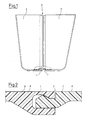
- FIG. 2 shows an enlarged detail of a connection as it connects two container halves on their side walls and in the bottom area.
- the connection points are designed as a groove 4 and tongue 5 that the projections 6 and 7 provided on these enable a clamping connection of the two halves.
- the surfaces of the container halves facing outwards also form a flat surface in the connection area.
- a container half has an edge design as a groove on its one side wall and the associated half of the bottom area up to the drainage opening in the middle, and an edge designed as a tongue in the other part.
- This construction allows two identical halves, which can be produced on a single machine, to be combined to form a container according to the invention.
- the use of plastic is preferred for producing a container according to the invention, since ceramic or glass due to the special construction of the tongue and groove element in the connection area do not withstand the stresses that occur when the container halves are joined together.
- Another advantage is that, because of the reusability of the containers, a reduction in the amount of waste is achieved, so that one can speak of an ideal solution to the problems at hand because of the increased economy achieved overall.
Abstract
Description
Die Erfindung betrifft einen Behälter zur Aufnahme des Wurzelballens von Pflanzen mit entlang einer Trennlinie an den Seitenwandungen und dem Behälterboden vorgesehenen, eine Trennung in Teilstücke erlaubenden, Verbindungsmitteln.The invention relates to a container for receiving the root ball of plants with connecting means provided along a dividing line on the side walls and the bottom of the container, allowing separation into sections.
Derartige Behälter bzw. Blumentöpfe, wie sie z. B. aus der DE-OS 36 16 034 bekannt sind, weisen den Nachteil auf, daß sie zum Austopfen in Teile zerlegt werden, d.h. zerstört werden müssen, und nicht wiederverwendbar sind.Such containers or flower pots, as z. B. from DE-OS 36 16 034 have the disadvantage that they are broken down into parts for stuffing, i.e. must be destroyed and are not reusable.
Blumentöpfe oder Pflanzgefäße werden heute nur noch selten aus Ton hergestellt. Im wesentlichen hat sich die Verwendung von Kunststoff auf diesem Gebiet durchgesetzt. Dieses liegt daran, daß der Verbraucher entweder die zu erwerbende Pflanze versetzen möchte, sei es in ein Beet oder in einen Blumenkasten, oder die Pflanze in einen individuell gestalteten, beispielsweise schmuckvollen Behälter umpflanzen möchte. Die von Pflanz- und Aufzucht-Anstalten verwendeten Behälter sind daher, soweit sie für Pflanzen verwendet werden, die zum Verkauf bestimmt sind, fast ausschließlich Einweg-Produkte; sie dienen lediglich dazu, eine Pflanze aufzuziehen und vorübergehend zu beherrbergen, um dem Erwerber eine unproblematische und saubere Versetzung der Pflanze mit einem möglichst unversehrten Wurzelballen zu ermöglichen.Flower pots or planters are now rarely made from clay. Essentially, the use of plastic has become established in this area. This is because the consumer either wants to move the plant to be acquired, be it in a bed or in a flower box, or transplant the plant into an individually designed, for example, decorative, container. The containers used by planting and rearing institutions are therefore, as far as they are used for plants intended for sale, almost exclusively disposable products; they only serve to raise and temporarily control a plant in order to enable the purchaser to move the plant easily and cleanly with the root ball as intact as possible.
Die von Märkten her bekannten Blumentöpfe und Pflanzgefäße weisen den Nachteil auf, daß sich häufig das Wurzelwerk der Pflanze durch die Abflußöffnung des Gefäßbodens hindurchzwängt und so ausweitet, daß der gesamte Wurzelballen nebst Pflanze quasie mit dem Gefäß "verwachsen" ist. Ein weiterer Nachteil ist, daß sich der Wurzelballen während des Wachstums und durch das Tränken der Pflanze ausdehnt und sich so fest und eng an die Gefäßwände anlegt, daß er von diesen nicht mehr gelöst werden kann, ohne daß er dabei selbst zumindest teilweise zerstört wird.The flower pots and planters known from markets have the disadvantage that the root system of the plant often squeezes through the outlet opening of the vessel bottom and expands in such a way that the entire root ball together with the plant is "grown together" with the vessel. Another disadvantage is that the root ball expands during the growth and by the watering of the plant and is so tight and close to the walls of the vessel that it can no longer be detached from it without being at least partially destroyed.
Will man eine Pflanze aus einem herkömmlichen Blumentopf zum Umpflanzen entfernen, muß man den Behälter nebst Wurzelballen und Pflanze umstülpen und schütteln, wobei es meist nicht möglich ist, die Pflanze aus dem Gefäß unversehrt zu entfernen.If you want to remove a plant from a conventional flower pot for transplanting, you have to invert and shake the container together with the root ball and the plant, whereby it is usually not possible to remove the plant from the container intact.
Es stellt sich daher für die Erfindung die Aufgabe, einen Behälter zur Aufnahme des Wurzelballens von Pflanzen, insbesondere einen Blumentopf, so auszugestalten, daß der Wurzelballen beim Austopfen oder Umtopfen nicht verformt oder beschädigt wird und auch Beschädigungen an Stängeln, Stielen usw. der betreffenden Pflanze vermieden werden. Insbesondere soll der Behälter nach dem Austopfen wieder zusammenfügbar und wiederverwendbar sein, um die relativ hohen Kosten für die Neubeschaffung großer Behälter zu sparen.It is therefore the object of the invention to design a container for holding the root ball of plants, in particular a flower pot, in such a way that the root ball is not deformed or damaged when being potted or repotted, and also damage to stems, stems, etc. of the plant in question be avoided. In particular, the container should be able to be put together and reused after being stuffed, in order to save the relatively high costs for the procurement of large containers.
Diese Aufgabe wird bei einem eingangs genannten Behälter erfindungsgemäß dadurch gelöst, daß die Verbindungsmittel an den Verbindungsstellen der Behälter-Teilstücke als, eine formschlüssige Verbindung der Teilstücke erlaubende, einander entsprechende Nut- und Feder-Elemente ausgestaltet sind. Dadurch, daß die erfindungsgemäßen Nut- und Federelemente einander entsprechende Vorsprünge aufweisen, wird ein klemmendes Ineinandergreifen der beiden Behälterteile entlang ihrer Trennlinien gewährleistet. Die Vorsprünge, die in Nut und Feder vorgesehen sind, ermöglichen ein Verklemmen der beiden Teilstücke dergestalt, daß die Haftung so groß ist, daß sie der Dehnungskraft des Wurzelballens infolge von Wachstum der Pflanzen ausreichend Widerstand leistet.This object is achieved according to the invention in a container mentioned at the outset in that the connecting means at the connecting points of the container sections are designed as mutually corresponding tongue and groove elements which permit a positive connection of the sections. The fact that the tongue and groove elements according to the invention have corresponding projections ensures a jamming interlocking of the two container parts along their dividing lines. The projections, which are provided in tongue and groove, enable the two sections to be clamped in such a way that the adhesion is so great that it provides sufficient resistance to the expansion force of the root ball due to the growth of the plants.
Besonders vorteilhaft ist, daß zur Herstellung beider Teilstücke eines Behälters lediglich eine einzige Spritzgußform erforderlich ist.It is particularly advantageous that only a single injection mold is required to produce both sections of a container.
Im folgenden wird ein Ausführungsbeispiel der Erfindung in der Zeichnung dargestellt und näher beschrieben. Es zeigen:
Figur 1 einen erfindungsgemäßen Behälter in Seitenansicht,Figur 2 einen Querschnitt durch ein erfindungsgemäßes Verbindungsdetail,Figur 3 einen Querschnitt durch eine Behälterhälfte.
- FIG. 1 shows a container according to the invention in side view,
- FIG. 2 shows a cross section through a connection detail according to the invention,
- Figure 3 shows a cross section through a container half.
Der in Figur 1 dargestellte erfindungsgemäße Behälter zur Aufnahme des Wurzelballens von Pflanzen besteht aus zwei identischen Teilstücken 3 und 3′, die entlang einer mittig links durch Behälter-Seitenwandung und Behälter-Boden verlaufenden Trennlinie, mittels einander entsprechender Nut 4- und Feder 5-Elemente ausgestattet entlang dieser Linie getrennt bzw. zusammengesetzt werden können. Die erfindungsgemäßen Nut- und Federelemente weisen die Besonderheit auf, daß sie an ihrer Oberfläche mit Vorsprüngen 6 und 7 versehen sind, die ineinander eingreifbar ausgestaltet sind und die durch diese eine Klemmverbindung herstellen, die dem Druck des sich durch Wachstum der Pflanze ausdehnenden Wurzelballens einen hinreichenden Widerstand bietet.The container according to the invention shown in Figure 1 for receiving the root ball of plants consists of two
Dadurch, daß diese Verbindungselemente entlang der gesamten Trennlinie sowohl in der Seitenwand als auch im Boden beider Hälften verlaufen und einander entsprechende Ausführung dergestalt aufweisen, daß eine Behälterhälfte jeweils in der einen Seitenwand und der bis zum Abflußloch reichenden Hälfte des Bodens eine Nut, in der zweiten Hälfte dieses Behältersegments eine Feder aufweist, können die einander entsprechenden Behälterhälften in nur einer einzigen Form und damit besonders kostengünstig hergestellt werden.Characterized in that these connecting elements run along the entire dividing line both in the side wall and in the bottom of both halves and have mutually corresponding design such that a container half in each of the one side wall and the half of the bottom extending to the drain hole has a groove, in the second Half of this container segment has a spring, the corresponding container halves can be produced in only a single shape and thus particularly inexpensively.
In Figur 2 ist in Vergrößerung ein Verbindungsdetail dargestellt, wie es zwei Behälterhälften an ihren Seitenwandungen wie auch im Bodenbereich verbindet. Dabei sind die Verbindungsstellen so als Nut 4 und Feder 5 ausgebildet, daß die an diesen vorgesehenen Vorsprünge 6 und 7 eine klemmende Verbindung beider Hälften ermöglichen. Dabei bilden die nach außen gewandten Oberflächen der Behälterhälften auch im Verbindungsbereich eine ebene Fläche.FIG. 2 shows an enlarged detail of a connection as it connects two container halves on their side walls and in the bottom area. The connection points are designed as a groove 4 and
Aus der Darstellung in Figur 3 ist ersichtlich, daß eine Behälterhälfte jeweils an ihrer einen Seitenwand sowie der dazugehörigen Hälfte des Bodenbereiches bis zur Entwässerungsöffnung in der Mitte eine Kantenausführung als Nut, in dem anderen Teil eine als Feder ausgebildete Kante aufweist.It can be seen from the illustration in FIG. 3 that a container half has an edge design as a groove on its one side wall and the associated half of the bottom area up to the drainage opening in the middle, and an edge designed as a tongue in the other part.
Durch diese Konstruktionsweise ist es möglich, zwei identische, auf einer einzigen Maschine herstellbare Hälften, zu einem erfindungsgemäßen Behälter zusammenzusetzen. Zur Herstellung eines erfindungsgemäßen Behälters wird die Verwendung von Kunststoff bevorzugt, da Keramik oder Glas wegen der besonderen Konstruktion von Nut- und Federelement im Verbindungsbereich den bei dem Zusammenfügen der Behälterhälften auftretenden Spannungen nicht widerstehen. Als weiterer Vorteil kommt hinzu, daß wegen der Wiederverwendbarkeit der Behälter eine Verringerung der Abfallmenge erreicht wird, so daß man wegen der insgesamt erreichten erhöhten Wirtschaftlichkeit von einer idealen Lösung der anstehenden Probleme sprechen kann.This construction allows two identical halves, which can be produced on a single machine, to be combined to form a container according to the invention. The use of plastic is preferred for producing a container according to the invention, since ceramic or glass due to the special construction of the tongue and groove element in the connection area do not withstand the stresses that occur when the container halves are joined together. Another advantage is that, because of the reusability of the containers, a reduction in the amount of waste is achieved, so that one can speak of an ideal solution to the problems at hand because of the increased economy achieved overall.
Claims (6)
Priority Applications (1)
| Application Number | Priority Date | Filing Date | Title |
|---|---|---|---|
| AT89104269T ATE72921T1 (en) | 1988-03-23 | 1989-03-10 | CONTAINER FOR ROOT BALL OF PLANTS. |
Applications Claiming Priority (4)
| Application Number | Priority Date | Filing Date | Title |
|---|---|---|---|
| DE3809697A DE3809697A1 (en) | 1988-03-23 | 1988-03-23 | Container for receiving the root ball of plants |
| DE3809697 | 1988-03-23 | ||
| DE8815259U | 1988-12-08 | ||
| DE8815259U DE8815259U1 (en) | 1988-03-23 | 1988-12-08 |
Publications (2)
| Publication Number | Publication Date |
|---|---|
| EP0334122A1 true EP0334122A1 (en) | 1989-09-27 |
| EP0334122B1 EP0334122B1 (en) | 1992-03-04 |
Family
ID=25866270
Family Applications (1)
| Application Number | Title | Priority Date | Filing Date |
|---|---|---|---|
| EP89104269A Expired - Lifetime EP0334122B1 (en) | 1988-03-23 | 1989-03-10 | Container for a plant root ball |
Country Status (5)
| Country | Link |
|---|---|
| EP (1) | EP0334122B1 (en) |
| JP (1) | JPH029323A (en) |
| DE (2) | DE8815259U1 (en) |
| DK (1) | DK136289A (en) |
| ES (1) | ES2031293T3 (en) |
Cited By (6)
| Publication number | Priority date | Publication date | Assignee | Title |
|---|---|---|---|---|
| DE4244399A1 (en) * | 1992-12-29 | 1994-07-07 | Thomas Von Garrel | Folding plant pot for mechanised plant packing |
| EP1574444A1 (en) * | 2004-03-11 | 2005-09-14 | Container Centralen Limited | Means for packaging flowers |
| EP1889536A1 (en) * | 2006-08-17 | 2008-02-20 | Butz, Agnes u. Eberhard | Plant pot |
| US11191221B2 (en) * | 2019-04-09 | 2021-12-07 | John W. Linnert | Container utilizing angle elements |
| DE202022100412U1 (en) | 2022-01-25 | 2022-02-25 | Christian Orth | flower box |
| DE102022101705A1 (en) | 2022-01-25 | 2023-07-27 | Christian Orth | flower box |
Families Citing this family (2)
| Publication number | Priority date | Publication date | Assignee | Title |
|---|---|---|---|---|
| DE19955488A1 (en) * | 1999-11-17 | 2001-06-07 | Enrico Hilbert | Plant pot has top section which can be removed from base and is in at least two parts |
| JP3824596B2 (en) * | 2003-03-26 | 2006-09-20 | サントリーフラワーズ株式会社 | Plant cultivation container |
Citations (5)
| Publication number | Priority date | Publication date | Assignee | Title |
|---|---|---|---|---|
| FR999480A (en) * | 1949-10-27 | 1952-01-31 | Pot with side perforations | |
| US2594307A (en) * | 1947-01-24 | 1952-04-29 | Ralph C Valenzuela | Sectional plant pot |
| FR1197267A (en) * | 1958-06-17 | 1959-11-30 | Separating brackets for agricultural use, provided with assembly profiles to make removable containers | |
| DE1298440B (en) * | 1965-07-30 | 1969-06-26 | Holzwerte Ag | Collapsible box |
| FR2214285A5 (en) * | 1973-01-17 | 1974-08-09 | Bouchet Papeterie | Storing and transporting packages - by cutting in half and stacking one inside the other |
Family Cites Families (3)
| Publication number | Priority date | Publication date | Assignee | Title |
|---|---|---|---|---|
| JPS4725337U (en) * | 1971-04-15 | 1972-11-21 | ||
| JPS4880334A (en) * | 1972-02-08 | 1973-10-27 | ||
| JPS52136743A (en) * | 1976-05-04 | 1977-11-15 | Rotocrop International Ltd | Container for gardening |
-
1988
- 1988-12-08 DE DE8815259U patent/DE8815259U1/de not_active Expired
-
1989
- 1989-03-10 ES ES198989104269T patent/ES2031293T3/en not_active Expired - Lifetime
- 1989-03-10 EP EP89104269A patent/EP0334122B1/en not_active Expired - Lifetime
- 1989-03-10 DE DE8989104269T patent/DE58900885D1/en not_active Expired - Lifetime
- 1989-03-21 DK DK136289A patent/DK136289A/en not_active Application Discontinuation
- 1989-03-23 JP JP1073675A patent/JPH029323A/en active Pending
Patent Citations (5)
| Publication number | Priority date | Publication date | Assignee | Title |
|---|---|---|---|---|
| US2594307A (en) * | 1947-01-24 | 1952-04-29 | Ralph C Valenzuela | Sectional plant pot |
| FR999480A (en) * | 1949-10-27 | 1952-01-31 | Pot with side perforations | |
| FR1197267A (en) * | 1958-06-17 | 1959-11-30 | Separating brackets for agricultural use, provided with assembly profiles to make removable containers | |
| DE1298440B (en) * | 1965-07-30 | 1969-06-26 | Holzwerte Ag | Collapsible box |
| FR2214285A5 (en) * | 1973-01-17 | 1974-08-09 | Bouchet Papeterie | Storing and transporting packages - by cutting in half and stacking one inside the other |
Cited By (6)
| Publication number | Priority date | Publication date | Assignee | Title |
|---|---|---|---|---|
| DE4244399A1 (en) * | 1992-12-29 | 1994-07-07 | Thomas Von Garrel | Folding plant pot for mechanised plant packing |
| EP1574444A1 (en) * | 2004-03-11 | 2005-09-14 | Container Centralen Limited | Means for packaging flowers |
| EP1889536A1 (en) * | 2006-08-17 | 2008-02-20 | Butz, Agnes u. Eberhard | Plant pot |
| US11191221B2 (en) * | 2019-04-09 | 2021-12-07 | John W. Linnert | Container utilizing angle elements |
| DE202022100412U1 (en) | 2022-01-25 | 2022-02-25 | Christian Orth | flower box |
| DE102022101705A1 (en) | 2022-01-25 | 2023-07-27 | Christian Orth | flower box |
Also Published As
| Publication number | Publication date |
|---|---|
| DE58900885D1 (en) | 1992-04-09 |
| DK136289D0 (en) | 1989-03-21 |
| JPH029323A (en) | 1990-01-12 |
| DE8815259U1 (en) | 1989-06-15 |
| DK136289A (en) | 1989-09-24 |
| EP0334122B1 (en) | 1992-03-04 |
| ES2031293T3 (en) | 1992-12-01 |
Similar Documents
| Publication | Publication Date | Title |
|---|---|---|
| DE9117301U1 (en) | Small container with plug connection | |
| DE2634380A1 (en) | INTO ANOTHER PLUG-IN CONTAINER MADE OF ELASTIC PLASTIC | |
| EP3576518B1 (en) | Tray for cultivating plants, and system comprising a tray and plant pot | |
| EP0334122A1 (en) | Container for a plant root ball | |
| DE2507823A1 (en) | PACKAGING UNIT FROM CONTAINERS | |
| DE2119359A1 (en) | Bottle opener. AnmrHuff, Otto, 4630 Bochum | |
| DE2646024A1 (en) | RELEASABLE CONNECTOR | |
| DE4325205A1 (en) | Container for food, in particular for serving, storing and transporting, and the associated connecting body | |
| EP0965633B1 (en) | Cell culture vessel for the cultivation of non-adherent cells | |
| DE3800019A1 (en) | Apparatus for the long-term tending, in particular, of plants, and process for the production of the apparatus | |
| DE19911326A1 (en) | Device for growing human or animal tissue | |
| EP0392273B1 (en) | Divisible plastic bottle case | |
| DE3109331A1 (en) | Stackable right parallelepipedal container | |
| DE102005040996B3 (en) | Holder plants e.g. tomatoes, beans or plants with relatively small load-bearing stems has two clamping parts which are connected to the holding clamp for stems of plant and the holding clamp, which restricts a through opening for stems | |
| DE3809697A1 (en) | Container for receiving the root ball of plants | |
| DE2345899A1 (en) | Plant growth hydroponics vessel insert - is like flower-pot and self-supporting, with slots for water passages to fit into vessel | |
| WO1994027876A1 (en) | Stackable nestable containers | |
| DE1857288U (en) | GROWING POT. | |
| EP0596519B1 (en) | Flowerpot, especially transplanting pot | |
| DE808965C (en) | Underground cable entry box | |
| DD244063A5 (en) | PLASTIC CANE OR BOTTLE, IN PARTICULAR PLASTIC COAT OF AN INSULATING CAN OR BOTTLE, WITH A RELIEF ORNAMENT ON THE COAT | |
| DE3130698C2 (en) | Method and device for inserting plant bodies in plant trays | |
| DE102021122401A1 (en) | plant pot | |
| CH661406A5 (en) | Cultivation shell for raising young plants | |
| DE8121160U1 (en) | Device for stacking bottles |
Legal Events
| Date | Code | Title | Description |
|---|---|---|---|
| PUAI | Public reference made under article 153(3) epc to a published international application that has entered the european phase |
Free format text: ORIGINAL CODE: 0009012 |
|
| AK | Designated contracting states |
Kind code of ref document: A1 Designated state(s): AT BE CH DE ES FR GB IT LI NL SE |
|
| 17P | Request for examination filed |
Effective date: 19900207 |
|
| 17Q | First examination report despatched |
Effective date: 19901221 |
|
| GRAA | (expected) grant |
Free format text: ORIGINAL CODE: 0009210 |
|
| AK | Designated contracting states |
Kind code of ref document: B1 Designated state(s): AT BE CH DE ES FR GB IT LI NL SE |
|
| REF | Corresponds to: |
Ref document number: 72921 Country of ref document: AT Date of ref document: 19920315 Kind code of ref document: T |
|
| PGFP | Annual fee paid to national office [announced via postgrant information from national office to epo] |
Ref country code: NL Payment date: 19920331 Year of fee payment: 4 |
|
| REF | Corresponds to: |
Ref document number: 58900885 Country of ref document: DE Date of ref document: 19920409 |
|
| PGFP | Annual fee paid to national office [announced via postgrant information from national office to epo] |
Ref country code: DE Payment date: 19920526 Year of fee payment: 4 |
|
| PGFP | Annual fee paid to national office [announced via postgrant information from national office to epo] |
Ref country code: SE Payment date: 19920527 Year of fee payment: 4 Ref country code: FR Payment date: 19920527 Year of fee payment: 4 Ref country code: ES Payment date: 19920527 Year of fee payment: 4 |
|
| ITF | It: translation for a ep patent filed |
Owner name: DE DOMINICIS & MAYER S.R.L. |
|
| PGFP | Annual fee paid to national office [announced via postgrant information from national office to epo] |
Ref country code: CH Payment date: 19920530 Year of fee payment: 4 |
|
| PGFP | Annual fee paid to national office [announced via postgrant information from national office to epo] |
Ref country code: BE Payment date: 19920604 Year of fee payment: 4 |
|
| PGFP | Annual fee paid to national office [announced via postgrant information from national office to epo] |
Ref country code: AT Payment date: 19920619 Year of fee payment: 4 |
|
| GBT | Gb: translation of ep patent filed (gb section 77(6)(a)/1977) | ||
| ET | Fr: translation filed | ||
| REG | Reference to a national code |
Ref country code: ES Ref legal event code: FG2A Ref document number: 2031293 Country of ref document: ES Kind code of ref document: T3 |
|
| PLBE | No opposition filed within time limit |
Free format text: ORIGINAL CODE: 0009261 |
|
| STAA | Information on the status of an ep patent application or granted ep patent |
Free format text: STATUS: NO OPPOSITION FILED WITHIN TIME LIMIT |
|
| 26N | No opposition filed | ||
| PG25 | Lapsed in a contracting state [announced via postgrant information from national office to epo] |
Ref country code: GB Effective date: 19930310 Ref country code: AT Effective date: 19930310 |
|
| PG25 | Lapsed in a contracting state [announced via postgrant information from national office to epo] |
Ref country code: SE Effective date: 19930311 Ref country code: ES Free format text: LAPSE BECAUSE OF NON-PAYMENT OF DUE FEES Effective date: 19930311 |
|
| PG25 | Lapsed in a contracting state [announced via postgrant information from national office to epo] |
Ref country code: LI Effective date: 19930331 Ref country code: CH Effective date: 19930331 Ref country code: BE Effective date: 19930331 |
|
| BERE | Be: lapsed |
Owner name: PREIN FRANZ Effective date: 19930331 |
|
| PG25 | Lapsed in a contracting state [announced via postgrant information from national office to epo] |
Ref country code: NL Effective date: 19931001 |
|
| GBPC | Gb: european patent ceased through non-payment of renewal fee |
Effective date: 19930310 |
|
| NLV4 | Nl: lapsed or anulled due to non-payment of the annual fee | ||
| PG25 | Lapsed in a contracting state [announced via postgrant information from national office to epo] |
Ref country code: FR Effective date: 19931130 |
|
| REG | Reference to a national code |
Ref country code: CH Ref legal event code: PL |
|
| PG25 | Lapsed in a contracting state [announced via postgrant information from national office to epo] |
Ref country code: DE Effective date: 19931201 |
|
| REG | Reference to a national code |
Ref country code: FR Ref legal event code: ST |
|
| EUG | Se: european patent has lapsed |
Ref document number: 89104269.9 Effective date: 19931008 |
|
| REG | Reference to a national code |
Ref country code: ES Ref legal event code: FD2A Effective date: 19990405 |
|
| PG25 | Lapsed in a contracting state [announced via postgrant information from national office to epo] |
Ref country code: IT Free format text: LAPSE BECAUSE OF NON-PAYMENT OF DUE FEES Effective date: 20050310 |