EP0334073A2 - Method and apparatus for producing formed plastic sheets - Google Patents
Method and apparatus for producing formed plastic sheets Download PDFInfo
- Publication number
- EP0334073A2 EP0334073A2 EP89103715A EP89103715A EP0334073A2 EP 0334073 A2 EP0334073 A2 EP 0334073A2 EP 89103715 A EP89103715 A EP 89103715A EP 89103715 A EP89103715 A EP 89103715A EP 0334073 A2 EP0334073 A2 EP 0334073A2
- Authority
- EP
- European Patent Office
- Prior art keywords
- smoothing
- hood
- molding tool
- mold
- plastic
- Prior art date
- Legal status (The legal status is an assumption and is not a legal conclusion. Google has not performed a legal analysis and makes no representation as to the accuracy of the status listed.)
- Withdrawn
Links
Images
Classifications
-
- B—PERFORMING OPERATIONS; TRANSPORTING
- B29—WORKING OF PLASTICS; WORKING OF SUBSTANCES IN A PLASTIC STATE IN GENERAL
- B29C—SHAPING OR JOINING OF PLASTICS; SHAPING OF MATERIAL IN A PLASTIC STATE, NOT OTHERWISE PROVIDED FOR; AFTER-TREATMENT OF THE SHAPED PRODUCTS, e.g. REPAIRING
- B29C41/00—Shaping by coating a mould, core or other substrate, i.e. by depositing material and stripping-off the shaped article; Apparatus therefor
- B29C41/34—Component parts, details or accessories; Auxiliary operations
- B29C41/46—Heating or cooling
-
- B—PERFORMING OPERATIONS; TRANSPORTING
- B29—WORKING OF PLASTICS; WORKING OF SUBSTANCES IN A PLASTIC STATE IN GENERAL
- B29C—SHAPING OR JOINING OF PLASTICS; SHAPING OF MATERIAL IN A PLASTIC STATE, NOT OTHERWISE PROVIDED FOR; AFTER-TREATMENT OF THE SHAPED PRODUCTS, e.g. REPAIRING
- B29C33/00—Moulds or cores; Details thereof or accessories therefor
- B29C33/02—Moulds or cores; Details thereof or accessories therefor with incorporated heating or cooling means
- B29C33/06—Moulds or cores; Details thereof or accessories therefor with incorporated heating or cooling means using radiation, e.g. electro-magnetic waves, induction heating
-
- B—PERFORMING OPERATIONS; TRANSPORTING
- B29—WORKING OF PLASTICS; WORKING OF SUBSTANCES IN A PLASTIC STATE IN GENERAL
- B29C—SHAPING OR JOINING OF PLASTICS; SHAPING OF MATERIAL IN A PLASTIC STATE, NOT OTHERWISE PROVIDED FOR; AFTER-TREATMENT OF THE SHAPED PRODUCTS, e.g. REPAIRING
- B29C71/00—After-treatment of articles without altering their shape; Apparatus therefor
- B29C71/02—Thermal after-treatment
-
- B—PERFORMING OPERATIONS; TRANSPORTING
- B29—WORKING OF PLASTICS; WORKING OF SUBSTANCES IN A PLASTIC STATE IN GENERAL
- B29C—SHAPING OR JOINING OF PLASTICS; SHAPING OF MATERIAL IN A PLASTIC STATE, NOT OTHERWISE PROVIDED FOR; AFTER-TREATMENT OF THE SHAPED PRODUCTS, e.g. REPAIRING
- B29C33/00—Moulds or cores; Details thereof or accessories therefor
- B29C33/02—Moulds or cores; Details thereof or accessories therefor with incorporated heating or cooling means
-
- B—PERFORMING OPERATIONS; TRANSPORTING
- B29—WORKING OF PLASTICS; WORKING OF SUBSTANCES IN A PLASTIC STATE IN GENERAL
- B29C—SHAPING OR JOINING OF PLASTICS; SHAPING OF MATERIAL IN A PLASTIC STATE, NOT OTHERWISE PROVIDED FOR; AFTER-TREATMENT OF THE SHAPED PRODUCTS, e.g. REPAIRING
- B29C41/00—Shaping by coating a mould, core or other substrate, i.e. by depositing material and stripping-off the shaped article; Apparatus therefor
- B29C41/02—Shaping by coating a mould, core or other substrate, i.e. by depositing material and stripping-off the shaped article; Apparatus therefor for making articles of definite length, i.e. discrete articles
- B29C41/04—Rotational or centrifugal casting, i.e. coating the inside of a mould by rotating the mould
- B29C41/06—Rotational or centrifugal casting, i.e. coating the inside of a mould by rotating the mould about two or more axes
-
- Y—GENERAL TAGGING OF NEW TECHNOLOGICAL DEVELOPMENTS; GENERAL TAGGING OF CROSS-SECTIONAL TECHNOLOGIES SPANNING OVER SEVERAL SECTIONS OF THE IPC; TECHNICAL SUBJECTS COVERED BY FORMER USPC CROSS-REFERENCE ART COLLECTIONS [XRACs] AND DIGESTS
- Y10—TECHNICAL SUBJECTS COVERED BY FORMER USPC
- Y10S—TECHNICAL SUBJECTS COVERED BY FORMER USPC CROSS-REFERENCE ART COLLECTIONS [XRACs] AND DIGESTS
- Y10S264/00—Plastic and nonmetallic article shaping or treating: processes
- Y10S264/60—Processes of molding plastisols
Definitions
- the invention has for its object to provide a method and a device of the type mentioned so that with only a small amount of harmful vapors and gases, the investment in equipment and energy for smoothing the back of the plastic film can be reduced.
- the enclosed tool cavity provides only a very small volume with which the amount of harmful vapors and gases generated during post-smoothing can be kept within narrow limits, whereby escape into the environment is ensured can be excluded.
- the powder box can be kept in a closed position with the molding tool through the post-smoothing hood and the post-smoothing process without a separate post-smoothing station, such as a continuous furnace, when The mold can be transported further from the powder coating station to the cooling station.
- the cooling station has the further advantage that cooling can take place in the closed state, as a result of which no interference from water residues can occur on the surfaces of the molding tool and the plastic molding film.
Abstract
Description
Die Erfindung betrifft ein Verfahren und eine Vorrichtung zum Herstellen von Kunststoff-Formfolien gemäß Oberbegriff des Anspruchs 1The invention relates to a method and a device for producing molded plastic films according to the preamble of
Bei bekannten Verfahren und Vorrichtungen dieser Art wird das Formwerkzeug nach dem Beschichten durch eine auf dem Formwerkzeug aufschmelzende Kunststoffschicht durch einen Durchlaufofen transportiert, in dem die Rückseite der Kunststoffschicht erhitzt und auf diese Weise nachgeglättet wird. Dieses Verfahren erfordert einen aufwendigen Anlagen- und Energieaufwand, da ein verhälnismäßig großvolumiger Durchlaufofen zu installieren ist, in dem eine große Luftmenge zu erhitzen ist, wobei Einrichtungen vorzusehen sind, um aus diesen Luftmengen schädliche Dämpfe und Gase auszusondern.In known methods and devices of this type, the molding tool is transported after coating through a plastic layer melting on the molding tool through a continuous furnace in which the back of the plastic layer is heated and in this way smoothed. This method requires complex plant and energy expenditure, since a relatively large-volume continuous furnace has to be installed, in which a large amount of air has to be heated, and devices have to be provided in order to separate out harmful vapors and gases from these amounts of air.
Der Erfindung liegt die Aufgabe zugrunde, ein Verfahren und eine Vorrichtung der genannten Art so auszubilden, daß bei nur in geringem Maße anfallenden Mengen an schädlichen Dämpfen und Gasen der Anlagen- und Energieaufwand zum Nachglätten der Rückseite der Kunststoff-Formfolie vermindert werden kann.The invention has for its object to provide a method and a device of the type mentioned so that with only a small amount of harmful vapors and gases, the investment in equipment and energy for smoothing the back of the plastic film can be reduced.
Die Lösung der Aufgabe ist in Anspruch 1 angegeben. Die Unteransprüche geben vorteilhafte Maßnahmen und Ausgestaltungen der Erfindung an.The solution to the problem is specified in
Durch das Abdecken des Formwerkzeugs mittels einer mit einer Heizeinrichtung versehenen Nachglätthaube ist mit dem umschlossenen Werkzeughohlraum nur ein sehr geringes Volumen gegeben, mit dem die Menge der beim Nachglätten entstehenden schädlichen Dämpfe und Gase in engen Grenzen gehalten werden kann, wobei ein Entweichen in die Umwelt sicher ausgeschlossen werden kann. Darüberhinaus besteht der Vorteil, daß durch die Nachglätthaube der Pulverkasten mit dem Formwerkzeug in geschlossener Stellung gehalten werden kann und der Vorgang des Nachglättens ohne gesonderte Nachglättstation, wie z.B eien Durchlaufofen, beim Weitertransport des Formwerkzeugs von der Pulverbeschichtungsstation zur Kühlstation erfolgen kann. In der Kühlstation ergibt sich der weitere Vorteil, daß die Abkühlung im geschlossenen Zustand erfolgen kann, wodurch an den Oberflächen des Formwerkzeugs und der Kunststoff-Formfolie keine Störeinflüsse durch Wasserrückstände auftreten können.By covering the mold by means of a post-smoothing hood provided with a heating device, the enclosed tool cavity provides only a very small volume with which the amount of harmful vapors and gases generated during post-smoothing can be kept within narrow limits, whereby escape into the environment is ensured can be excluded. In addition, there is the advantage that the powder box can be kept in a closed position with the molding tool through the post-smoothing hood and the post-smoothing process without a separate post-smoothing station, such as a continuous furnace, when The mold can be transported further from the powder coating station to the cooling station. The cooling station has the further advantage that cooling can take place in the closed state, as a result of which no interference from water residues can occur on the surfaces of the molding tool and the plastic molding film.
In einer bevorzugten Ausführungsform besteht die Heizeinrichtung aus Strahlerelementen, wodurch die Rückseite der Kunststoff-Formfolie in besonders energie- und zeitsparender Weise nachgeglättet werden kann. Als Folge hiervon fallen auch nur geringe Mengen an schädlichen Dämpfen und Gasen an.In a preferred embodiment, the heating device consists of radiator elements, as a result of which the back of the plastic molded film can be smoothed in a particularly energy-saving and time-saving manner. As a result, only small amounts of harmful vapors and gases are generated.
Zur Vergleichmäßigung der Temperatur in dem vom Formwerkzeug und der Nachglätthaube umschlossenen Werkzeughohlraum ist in der Nachglätthaube ein Gebläse vorgesehen, mit dem eine Umwälzung der geschlossenen Gase erzielt werden kann.In order to equalize the temperature in the mold cavity enclosed by the mold and the smoothing hood, a blower is provided in the smoothing hood, with which a circulation of the closed gases can be achieved.
Eine Ausführungsform der Erfindung wird anhand der Zeichnung näher erläutert. Es zeigt :
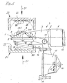
- Fig. 1 die Seitenansicht einer Formträgereinheit in der Strahlerheizstation mit einem Formwerkzeug in teilweiser Schnittdarstellung und mit an das Formwerkzeug herangefahrenen Heizstrahlerfeldern,
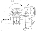
- Fig. 2 die Formträgereinheit in der Beschichtungsstation mit angekoppeltem Pulverbehälter und noch geöffneter Nachglätthaube,
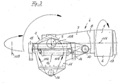
- Fig. 3 die Formträgereinheit mit geschlossener Nachglätthaube und Darstellung der Drehachsen um die das Formwerkzeug drehbar ist,
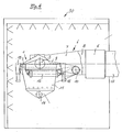
- Fig. 4 die Formträgereinheit mit geschlossener Nachglätthaube in der Kühlstation und,
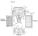
- Fig. 5 die Draufsicht auf die stark vereinfacht dargestellte Formträgereinheit mit den verschiedenen Bearbeitungsstationen.-
- 1 is a side view of a mold carrier unit in the radiator heating station with a mold in a partial sectional view and with radiant heater fields approached to the mold,
- 2 shows the mold carrier unit in the coating station with the powder container coupled and the post-smoothing hood still open,
- 3 the mold carrier unit with the closed smoothing hood and representation of the axes of rotation about which the mold can be rotated,
- 4 shows the mold carrier unit with the closed smoothing hood in the cooling station, and
- 5 shows the top view of the mold carrier unit shown in a highly simplified manner with the various processing stations.
Die Fig.1 bis 5 zeigen eine Formträgereinheit mit einem aus einer Galvanoschale bestehenden und teilweise geschnitten dargestellten Formwerkzeug 1, das in einer Halterung 2 angeordnet ist. Am Formwerkzeug 1 ist eine Anzahl von Temperaturmeßfühlern 3 angeordnet. Die Halterung 2 wird von einem gabelartigen Haltebügel 4 umfaßt und ist an diesem an zwei Drehgelenken 5 angelenkt. Der Haltebügel 4 besteht aus einem Querarm 6 und zwei Gelenkarmen 7 und 8 (Fig. 5), von denen in den Fig. 1 bis 4 der Gelenkarm 7 vollständig und der Gelenkarm 8 nur in einem Teilstück dargestellt sind.1 to 5 show a mold carrier unit with a
An der Halterung 2 ist ferner ein Halterahmen 9 angeordnet, an dem mittels eines Gelenks 10 eine Nachglätthaube 11 befestigt ist, die durch einen Stellzylinder 12 in eine offene Stellung gemäß der Darstellung nach Fig. 1 und 2 und in eine geschlossene Stellung gemäß der Darstellung nach Fig. 3 und 4 schwenkbar ist.On the
Im Bodenbereich der Nachglätthaube 11 sind Strahlerelemente 13 sowie ein Gebläse 14 angeordnet, mit dem im Inneren der Nachglätthaube 11, wie in Fig. 3 durch die Pfeile 114 dargestellt, eine Zirkulationsströmmung erzeugbar ist. An den oberen Randbereichen sind an der Nachglätthaube 11 hydraulisch betätigbare Verriegelungselemente 15 und 16 angeordnet mit denen die Nachglätthaube 11 in geschlossener Stellung (Fig. 3 und 4) mit der Halterung 2 verriegelbar ist.In the bottom area of the
Der Querarm 6 des Haltebügels 4 ist an einer Welle 17 befestigt, die in einem Träger 18 und in einer Königswelle 19 drehbar gelagert ist (Fig. 5).The
Das Formwerkzeug 1 ist bei geschlossener Nachglätthaube 11 im Drehgelenk 5 um eine erste Drehachse 105 und mittels der Welle 17 um eine zweite Drehachse 117 drehbar. Die gesamte Formträgereinheit ist mit der Königswelle 19 um die Schwenkachse 119 in die bestimmten Bearbeitungsstationen (Fig. 5) schwenkbar.The
In der ersten Bearbeitungsstation, der Strahlerheizstation befinden sich zwei Heizstrahlerfelder 20 und 21, diejeweils aus einem offenen Behälter 22 und 23 bestehen, auf dessen Bodenplatte 24 und 25 eine Anzahl von Einzelstrahlern 26 angeordnet sind.In the first processing station, the radiator heating station, there are two
Im Betrieb (Fig.1) werden bei geöffneter Nachglätthaube 11 die Heizstrahlerfelder 20 und 21 in Richtung der Pfeile 27 herangefahren, so daß die Einzelstrahler 26 des oberen Heizstrahlerfeldes 20 auf die nichtformgebende Oberfläche 201 und die Einzelstrahler 26 des unteren Heizstrahlerfeldes 21 auf die formgebende Oberfläche 101 des Formwerkzeugs 1 gerichtet sind.In operation (FIG. 1), with the
Nach der Erwärmung des Formwerkzeugs 1 in der Strahlerheizstation werden die Heizstrahlerfelder 20 und 21 entgegen der Richtung der Pfeile 27 auseinandergefahren, worauf die Formträgereinheit in die nächste Bearbeitungsstation, die Pulverbeschichtungsstation, geschwenkt wird. Dabei wird an das geöffnete Formwerkzeug 1 mittels einer Zuführeinrichtung 28 (Fig. 2) ein Pulverbehälter 29 angedockt, der durch nachfolgendes Schließen der Nachglätthaube 11 gegen das Formwerkzeug 1 gedrückt und in geschlossener Stellung gehalten wird.After the
Im weiteren wird der Pulverbehälter 29 nach erfolgter Rotation des geschlossenen Formwerkzeugs 1 um die Drehachsen 105 und 117 wieder entfernt, worauf die Nachglätthaube 11 wieder geschlossen und die Rückseite der Kunststoff-Formfolie 31 mit Strahlung aus den Strahlerelementen 13 der Nachglätthaube 11 beaufschlagt wird. Unter nochmaliger Rotation des Formwerkzeugs 1 um die Drehachsen 105 und 117 erfolgt dabei ein Nachgelieren bzw. ein Nachglätten der Kunststoff-Formfolie 31, wobei mittels des Gebläses 14 noch eine Vergleichmäßigung der Oberflächenbeheizung der Rückseite der Kunststoff-Formfolie 31 erzielt werden kann.Furthermore, the
Durch das in der Nachglätthaube 11 angeordnete Feld aus Strahlerelementen 13 reichen gegenüber den herkömmlichen Verfahren zum Nachglätten, bei denen aufwendige Wärmeöfen erforderlich sind, bereits geringe Heizleistungen aus.As a result of the array of
Der von der Nachglätthaube 11 und dem Formwerkzeug 1 umschlossene Werkzeughohlraum kann auch während des Nachgelierens zum Schutz vor Oxidation und/oder zum Kühlen mit Inertgas, beispielsweise Stickstoff, beaufschlagt werden. Dieses Gas kann über ein von der Königswelle 19 bis zum Werkzeughohlraum führendes Gasleitungssystem eingeleitet werden, das durch den Träger 18, die Welle 17 und den Haltebügel 4 verläuft, wobei an den Gelenkstellen bzw. den Rotationsachsen entsprechende Drehdurchführungen angeordnet sind.The tool cavity enclosed by the
Das Gasleitungssystem kann sowohl zum Einleiten von inertem Gas, als auch zum Absaugen von beim Nachglätten entstehenden schädlichen Dämpfen verwendet werden.The gas line system can be used both for the introduction of inert gas and for the extraction of harmful vapors that arise during smoothing.
Das Gasleitungssystem kann dabei so ausgestaltet sein, daß der Werkzeughohlraum sowohl an einen Zuführungskanal als auch an einen Abführungskanal (nicht dargestellt) angeschlossen ist.The gas line system can be designed in such a way that the tool cavity is connected to both a feed channel and a discharge channel (not shown).
Der Vorgang des Nachglättens kann auf dem Transport der Formträgereinheit von der Pulverbeschichtungsstation zur Kühlstation 30 erfolgen.The smoothing process can take place on the transport of the mold carrier unit from the powder coating station to the cooling station 30.
In der Kühlstation 30 wird das Formwerkzeug 1 bei geschlossener Nachglätthaube 11 mit Sprühwasser und/oder Luft abgekühlt, wobei der eingeschlossene Werkzeughohlraum gleichzeitig oder in einem bereits vorher eingeleiteten Arbeitsgang zur Unterstützung des Kühlvorganges noch durch eingeführtes Gas gekühlt werden kann.In the cooling station 30, the
Nach dem Abkühlen und dem Weitertansport der Formträgereinheit in die Entformstation wird die Nachglätthaube 11 aufgeklappt und die fertige Kunststoff-Formfolie 31 aus dem Formwerkzeug 1 entnommen.After cooling and further transport of the mold carrier unit into the demolding station, the
Claims (12)
Applications Claiming Priority (2)
| Application Number | Priority Date | Filing Date | Title |
|---|---|---|---|
| DE3809825A DE3809825A1 (en) | 1988-03-23 | 1988-03-23 | METHOD AND DEVICE FOR PRODUCING PLASTIC SHAPED FILMS |
| DE3809825 | 1988-03-23 |
Publications (2)
| Publication Number | Publication Date |
|---|---|
| EP0334073A2 true EP0334073A2 (en) | 1989-09-27 |
| EP0334073A3 EP0334073A3 (en) | 1990-12-27 |
Family
ID=6350503
Family Applications (1)
| Application Number | Title | Priority Date | Filing Date |
|---|---|---|---|
| EP19890103715 Withdrawn EP0334073A3 (en) | 1988-03-23 | 1989-03-03 | Method and apparatus for producing formed plastic sheets |
Country Status (4)
| Country | Link |
|---|---|
| US (1) | US4979888A (en) |
| EP (1) | EP0334073A3 (en) |
| JP (1) | JPH01278318A (en) |
| DE (1) | DE3809825A1 (en) |
Cited By (2)
| Publication number | Priority date | Publication date | Assignee | Title |
|---|---|---|---|---|
| DE4023878A1 (en) * | 1990-07-27 | 1992-01-30 | Bayerische Motoren Werke Ag | Equipment for thermo-forming plastic film - by smoothing back of film when heated by blown hot air system which is uniform and can also apply cooling air and save energy |
| WO2000003857A1 (en) * | 1998-07-13 | 2000-01-27 | Fröhle Med. Techn. Formteile Gmbh | Arrangement of a rotary device |
Families Citing this family (20)
| Publication number | Priority date | Publication date | Assignee | Title |
|---|---|---|---|---|
| US5415816A (en) | 1986-01-28 | 1995-05-16 | Q2100, Inc. | Method for the production of plastic lenses |
| US6201037B1 (en) | 1986-01-28 | 2001-03-13 | Ophthalmic Research Group International, Inc. | Plastic lens composition and method for the production thereof |
| US6730244B1 (en) | 1986-01-28 | 2004-05-04 | Q2100, Inc. | Plastic lens and method for the production thereof |
| US5362349A (en) * | 1992-07-07 | 1994-11-08 | The Standard Products Company | Plastic heat set molding |
| US5256354A (en) * | 1992-11-12 | 1993-10-26 | Davidson Textron Inc. | Method for forming an invisible tear seam |
| DE4309643C2 (en) * | 1993-03-25 | 2002-06-13 | Schuler Pressen Gmbh & Co | Transfer device for workpiece transport |
| US5514214A (en) | 1993-09-20 | 1996-05-07 | Q2100, Inc. | Eyeglass lens and mold spin coater |
| US5525274A (en) * | 1994-06-29 | 1996-06-11 | Davidson Textron Inc. | Process for manufacturing plastic microspheres |
| US5824738A (en) | 1994-10-07 | 1998-10-20 | Davidson Textron Inc. | Light stable aliphatic thermoplastic urethane elastomers and method of making same |
| US6022498A (en) | 1996-04-19 | 2000-02-08 | Q2100, Inc. | Methods for eyeglass lens curing using ultraviolet light |
| US6280171B1 (en) | 1996-06-14 | 2001-08-28 | Q2100, Inc. | El apparatus for eyeglass lens curing using ultraviolet light |
| US6632525B1 (en) | 2000-10-11 | 2003-10-14 | Textron Automotive Company, Inc. | Material and method for manufacturing plastic parts |
| ES2311625T3 (en) * | 2001-10-09 | 2009-02-16 | COLLINS & AIKMAN AUTOMOTIVE COMPANY INC. | PROCEDURE AND APPLIANCE TO CONFORM PLASTIC COATINGS. |
| US7550103B2 (en) * | 2001-10-09 | 2009-06-23 | International Automotive Components Group North America, Inc. | Plastic skin forming process |
| US6981862B2 (en) * | 2003-09-09 | 2006-01-03 | Toyota Technical Center Usa, Inc. | Slush molding machine |
| US20050240040A1 (en) * | 2004-04-26 | 2005-10-27 | Kendall J K | Process for producing esters employing hydrolyzable catalysts |
| WO2008077146A1 (en) | 2006-12-20 | 2008-06-26 | Visteon Global Technologies, Inc. | Double-cast slush molding compositions |
| US20150021831A1 (en) * | 2013-07-17 | 2015-01-22 | James PEPLINSKI | Injection molding method with infrared preheat |
| US11007685B1 (en) * | 2018-09-26 | 2021-05-18 | United States Of America As Represented By The Administrator Of Nasa | Fabricating ultra-thin structured polymer films |
| CN110928344B (en) * | 2019-10-12 | 2021-08-20 | 国网吉林省电力有限公司白山供电公司 | Transformer substation environment monitoring system |
Citations (7)
| Publication number | Priority date | Publication date | Assignee | Title |
|---|---|---|---|---|
| US2583330A (en) * | 1948-12-02 | 1952-01-22 | Us Stoneware Co | Apparatus for giving an internal gloss finish to a tube or the like of heat plastic material |
| US2908039A (en) * | 1956-07-25 | 1959-10-13 | Pastushin Aviat Corp | Apparatus for producing objects of cured plastic material |
| DE1704221A1 (en) * | 1966-05-26 | 1971-05-06 | Nat Distillers Chem Corp | Method and apparatus for rotary pressing for forming a pressed part |
| EP0001011A1 (en) * | 1977-08-24 | 1979-03-07 | British Industrial Plastics Limited | Improvements in or relating to moulding machines |
| US4204822A (en) * | 1977-08-24 | 1980-05-27 | British Industrial Plastics Ltd. | Moulding machine |
| JPS627518A (en) * | 1985-07-05 | 1987-01-14 | Toyota Motor Corp | Expansion slush molding equipment |
| JPS627517A (en) * | 1985-07-03 | 1987-01-14 | Toyota Motor Corp | Expansion slush molding equipment |
Family Cites Families (9)
| Publication number | Priority date | Publication date | Assignee | Title |
|---|---|---|---|---|
| GB1327200A (en) * | 1969-11-26 | 1973-08-15 | Plastic Rotational Mould Ltd | Rotational moulding apparatus |
| FR2134222A1 (en) * | 1971-04-21 | 1972-12-08 | Superior | Moulding travelling bags - using polyvinyl based plastisol sprayed onto mould |
| US3771928A (en) * | 1971-06-28 | 1973-11-13 | T Gostyn | Apparatus for molding polyurethane articles |
| JPS529225B2 (en) * | 1972-12-29 | 1977-03-15 | ||
| JPS58197011A (en) * | 1982-05-12 | 1983-11-16 | Honda Motor Co Ltd | Manufacturing method and equipment for skin forming material |
| DE3417727A1 (en) * | 1983-06-25 | 1985-01-10 | Ymos Aktiengesellschaft Industrieprodukte, 6053 Obertshausen | Process and device for producing thin-walled articles from plastic |
| FR2562466B1 (en) * | 1984-04-06 | 1987-02-20 | Datome | ROTOMOLDING MACHINE |
| DE8429732U1 (en) * | 1984-10-10 | 1985-02-28 | Rhein-Conti Kunststoff-Technik Gmbh, 6900 Heidelberg | ROTATIONAL DEVICE |
| JPS6237112A (en) * | 1985-08-13 | 1987-02-18 | Tokai Kasei Kogyo Kk | Slush molding method for powdery material |
-
1988
- 1988-03-23 DE DE3809825A patent/DE3809825A1/en not_active Withdrawn
-
1989
- 1989-02-15 US US07/311,233 patent/US4979888A/en not_active Expired - Fee Related
- 1989-03-03 EP EP19890103715 patent/EP0334073A3/en not_active Withdrawn
- 1989-03-23 JP JP1069421A patent/JPH01278318A/en active Pending
Patent Citations (7)
| Publication number | Priority date | Publication date | Assignee | Title |
|---|---|---|---|---|
| US2583330A (en) * | 1948-12-02 | 1952-01-22 | Us Stoneware Co | Apparatus for giving an internal gloss finish to a tube or the like of heat plastic material |
| US2908039A (en) * | 1956-07-25 | 1959-10-13 | Pastushin Aviat Corp | Apparatus for producing objects of cured plastic material |
| DE1704221A1 (en) * | 1966-05-26 | 1971-05-06 | Nat Distillers Chem Corp | Method and apparatus for rotary pressing for forming a pressed part |
| EP0001011A1 (en) * | 1977-08-24 | 1979-03-07 | British Industrial Plastics Limited | Improvements in or relating to moulding machines |
| US4204822A (en) * | 1977-08-24 | 1980-05-27 | British Industrial Plastics Ltd. | Moulding machine |
| JPS627517A (en) * | 1985-07-03 | 1987-01-14 | Toyota Motor Corp | Expansion slush molding equipment |
| JPS627518A (en) * | 1985-07-05 | 1987-01-14 | Toyota Motor Corp | Expansion slush molding equipment |
Non-Patent Citations (2)
| Title |
|---|
| PATENT ABSTRACTS OF JAPAN, Band 11, Nr. 175 (M-596)[2622], 5. Juni 1987; & JP-A-62 007 517 (TOYOTA) 14-01-1987 * |
| PATENT ABSTRACTS OF JAPAN, Band 11, Nr. 175 (M-596)[2622], 5. Juni 1987; & JP-A-62 007 518 (TOYOTA) 14-01-1987 * |
Cited By (2)
| Publication number | Priority date | Publication date | Assignee | Title |
|---|---|---|---|---|
| DE4023878A1 (en) * | 1990-07-27 | 1992-01-30 | Bayerische Motoren Werke Ag | Equipment for thermo-forming plastic film - by smoothing back of film when heated by blown hot air system which is uniform and can also apply cooling air and save energy |
| WO2000003857A1 (en) * | 1998-07-13 | 2000-01-27 | Fröhle Med. Techn. Formteile Gmbh | Arrangement of a rotary device |
Also Published As
| Publication number | Publication date |
|---|---|
| EP0334073A3 (en) | 1990-12-27 |
| DE3809825A1 (en) | 1989-10-05 |
| US4979888A (en) | 1990-12-25 |
| JPH01278318A (en) | 1989-11-08 |
Similar Documents
| Publication | Publication Date | Title |
|---|---|---|
| EP0334073A2 (en) | Method and apparatus for producing formed plastic sheets | |
| EP0502378B1 (en) | Apparatus and method to produce synthetic material skins and objects from plastic | |
| DE2817030C2 (en) | Device for the production of objects of different wall thickness from a plastic that can be processed under the influence of heat | |
| DE2926534C2 (en) | Method of applying a heat-shrinkable sleeve to a bottle-shaped container | |
| DE2755029C2 (en) | Method and device for applying a plastic layer to glass containers | |
| DE3128221C2 (en) | ||
| DE2908122C2 (en) | Process for heating preforms for blow molding containers made of thermoplastic material | |
| CH649960A5 (en) | METHOD AND DEVICE FOR PACKING OBJECTS IN THERMOPLASTIC FILM MATERIAL. | |
| DE2713407A1 (en) | PROCESS FOR HOT SHRINKING THERMOPLASTIC SLEEVE WRAPPING ON GLASS CONTAINERS | |
| DE10012506A1 (en) | Coating device for lenses | |
| DE2315450A1 (en) | METHOD AND DEVICE FOR APPLYING A COATING MADE OF POWDERED RESINS, PAINTS AND THE LIKE, ON RING-SHAPED BULGES AND / OR BULKETS, IN PARTICULAR ON THE BETWEEN RIM AND WHEEL DISC OF DISTANCE VEHICLES | |
| DE4142109C2 (en) | Device for the production of molded plastic films | |
| DE3637272A1 (en) | FOAM CASTING DEVICE FOR HOLLOW BODIES | |
| EP0556664B1 (en) | Method and apparatus for heating a mould | |
| DE3417727C2 (en) | ||
| EP0334074A2 (en) | Method and apparatus for producing formed plastic sheets | |
| EP0444228A1 (en) | Apparatus for moulding preforms | |
| DE1577905C3 (en) | Device for coating the inside of floors of large metallic containers with a powdery one! Covering material | |
| EP1655121B1 (en) | Process and apparatus for manufacturing shaped plastic sheets | |
| EP0030918A1 (en) | Method and apparatus for applying a sealing film strip to the edge of a blank | |
| DE19602886C2 (en) | Method for producing a plastic skin and device for carrying out the method | |
| DE19532285C1 (en) | Tool heating process and process plant for prodn. of sintered plastic shells | |
| DE19612210A1 (en) | Method of applying decorative coatings to supporting parts | |
| EP0245625B1 (en) | Process for manufacturing a body by way of shaped build-up welding | |
| DE10022140A1 (en) | Device for melting adhesive and applying a specific amount of plastic to a workpiece incorporates an applicator device with an adhesive applicator and a melting device with a heating cylinder for heating up the adhesive. |
Legal Events
| Date | Code | Title | Description |
|---|---|---|---|
| PUAI | Public reference made under article 153(3) epc to a published international application that has entered the european phase |
Free format text: ORIGINAL CODE: 0009012 |
|
| AK | Designated contracting states |
Kind code of ref document: A2 Designated state(s): DE ES FR GB IT SE |
|
| PUAL | Search report despatched |
Free format text: ORIGINAL CODE: 0009013 |
|
| AK | Designated contracting states |
Kind code of ref document: A3 Designated state(s): DE ES FR GB IT SE |
|
| STAA | Information on the status of an ep patent application or granted ep patent |
Free format text: STATUS: THE APPLICATION IS DEEMED TO BE WITHDRAWN |
|
| 18D | Application deemed to be withdrawn |
Effective date: 19910628 |