EP0333798B1 - Appareil de reconnaissance de formes - Google Patents
Appareil de reconnaissance de formes Download PDFInfo
- Publication number
- EP0333798B1 EP0333798B1 EP88907744A EP88907744A EP0333798B1 EP 0333798 B1 EP0333798 B1 EP 0333798B1 EP 88907744 A EP88907744 A EP 88907744A EP 88907744 A EP88907744 A EP 88907744A EP 0333798 B1 EP0333798 B1 EP 0333798B1
- Authority
- EP
- European Patent Office
- Prior art keywords
- input
- vector
- output
- vectors
- array
- Prior art date
- Legal status (The legal status is an assumption and is not a legal conclusion. Google has not performed a legal analysis and makes no representation as to the accuracy of the status listed.)
- Expired - Lifetime
Links
- 238000003909 pattern recognition Methods 0.000 title claims description 24
- 239000013598 vector Substances 0.000 claims abstract description 172
- 238000003491 array Methods 0.000 claims abstract description 15
- 238000012549 training Methods 0.000 claims abstract description 12
- 230000002123 temporal effect Effects 0.000 claims abstract description 11
- 230000008859 change Effects 0.000 claims description 8
- 238000012545 processing Methods 0.000 claims description 7
- 238000005070 sampling Methods 0.000 claims description 6
- 238000012986 modification Methods 0.000 claims description 5
- 230000004048 modification Effects 0.000 claims description 5
- 230000001419 dependent effect Effects 0.000 claims description 4
- 230000003247 decreasing effect Effects 0.000 claims description 3
- 238000013507 mapping Methods 0.000 claims description 3
- 238000004458 analytical method Methods 0.000 claims description 2
- 230000005669 field effect Effects 0.000 claims 1
- 230000002688 persistence Effects 0.000 abstract description 16
- 210000002569 neuron Anatomy 0.000 description 113
- 239000010410 layer Substances 0.000 description 86
- 238000000034 method Methods 0.000 description 25
- 230000005284 excitation Effects 0.000 description 22
- 230000001537 neural effect Effects 0.000 description 18
- 230000008569 process Effects 0.000 description 13
- 230000000946 synaptic effect Effects 0.000 description 12
- 230000006870 function Effects 0.000 description 11
- 238000010304 firing Methods 0.000 description 9
- 208000003098 Ganglion Cysts Diseases 0.000 description 8
- 208000005400 Synovial Cyst Diseases 0.000 description 7
- 238000004422 calculation algorithm Methods 0.000 description 5
- 239000011229 interlayer Substances 0.000 description 4
- 238000013459 approach Methods 0.000 description 3
- 230000006978 adaptation Effects 0.000 description 2
- 230000000694 effects Effects 0.000 description 2
- 238000010606 normalization Methods 0.000 description 2
- 230000003466 anti-cipated effect Effects 0.000 description 1
- 230000008901 benefit Effects 0.000 description 1
- 238000004364 calculation method Methods 0.000 description 1
- 230000006835 compression Effects 0.000 description 1
- 238000007906 compression Methods 0.000 description 1
- 239000004020 conductor Substances 0.000 description 1
- 238000012937 correction Methods 0.000 description 1
- 238000006880 cross-coupling reaction Methods 0.000 description 1
- 230000001934 delay Effects 0.000 description 1
- 238000010586 diagram Methods 0.000 description 1
- 238000002474 experimental method Methods 0.000 description 1
- 238000000605 extraction Methods 0.000 description 1
- 230000006872 improvement Effects 0.000 description 1
- 238000012886 linear function Methods 0.000 description 1
- 238000012544 monitoring process Methods 0.000 description 1
- 210000000118 neural pathway Anatomy 0.000 description 1
- 238000012567 pattern recognition method Methods 0.000 description 1
- 230000000717 retained effect Effects 0.000 description 1
- 238000004088 simulation Methods 0.000 description 1
- URWAJWIAIPFPJE-YFMIWBNJSA-N sisomycin Chemical compound O1C[C@@](O)(C)[C@H](NC)[C@@H](O)[C@H]1O[C@@H]1[C@@H](O)[C@H](O[C@@H]2[C@@H](CC=C(CN)O2)N)[C@@H](N)C[C@H]1N URWAJWIAIPFPJE-YFMIWBNJSA-N 0.000 description 1
- 230000003595 spectral effect Effects 0.000 description 1
- 238000001228 spectrum Methods 0.000 description 1
- 238000010183 spectrum analysis Methods 0.000 description 1
- 230000004936 stimulating effect Effects 0.000 description 1
- 230000000638 stimulation Effects 0.000 description 1
Images


Classifications
-
- G—PHYSICS
- G10—MUSICAL INSTRUMENTS; ACOUSTICS
- G10L—SPEECH ANALYSIS TECHNIQUES OR SPEECH SYNTHESIS; SPEECH RECOGNITION; SPEECH OR VOICE PROCESSING TECHNIQUES; SPEECH OR AUDIO CODING OR DECODING
- G10L15/00—Speech recognition
- G10L15/08—Speech classification or search
- G10L15/16—Speech classification or search using artificial neural networks
-
- G—PHYSICS
- G06—COMPUTING; CALCULATING OR COUNTING
- G06N—COMPUTING ARRANGEMENTS BASED ON SPECIFIC COMPUTATIONAL MODELS
- G06N3/00—Computing arrangements based on biological models
- G06N3/02—Neural networks
- G06N3/04—Architecture, e.g. interconnection topology
-
- G—PHYSICS
- G06—COMPUTING; CALCULATING OR COUNTING
- G06N—COMPUTING ARRANGEMENTS BASED ON SPECIFIC COMPUTATIONAL MODELS
- G06N3/00—Computing arrangements based on biological models
- G06N3/02—Neural networks
- G06N3/06—Physical realisation, i.e. hardware implementation of neural networks, neurons or parts of neurons
- G06N3/063—Physical realisation, i.e. hardware implementation of neural networks, neurons or parts of neurons using electronic means
-
- G—PHYSICS
- G06—COMPUTING; CALCULATING OR COUNTING
- G06V—IMAGE OR VIDEO RECOGNITION OR UNDERSTANDING
- G06V30/00—Character recognition; Recognising digital ink; Document-oriented image-based pattern recognition
- G06V30/10—Character recognition
- G06V30/19—Recognition using electronic means
- G06V30/192—Recognition using electronic means using simultaneous comparisons or correlations of the image signals with a plurality of references
- G06V30/194—References adjustable by an adaptive method, e.g. learning
-
- G—PHYSICS
- G10—MUSICAL INSTRUMENTS; ACOUSTICS
- G10L—SPEECH ANALYSIS TECHNIQUES OR SPEECH SYNTHESIS; SPEECH RECOGNITION; SPEECH OR VOICE PROCESSING TECHNIQUES; SPEECH OR AUDIO CODING OR DECODING
- G10L15/00—Speech recognition
Definitions
- the invention relates to methods and apparatus for pattern recognition, and particularly, though not exclusively, speech recognition.
- the invention is particularly concerned with monitoring temporal sequences of input vectors so as to recognise particular patterns.
- an "N dimensional vector” comprises a group of N values, each value corresponding to a respective dimension of the vector.
- the values may be represented by analogue signals or digitally.
- Such a vector has a magnitude which may be, for example, defined by the square root of the sum of the squares of the values, and also a direction in N dimensional space.
- scalar quantities except for N will be represented by lower case letters, and vector quantities by upper case letters.
- Vectors of this type can in particular be derived from an analysis of human speech.
- an analogue signal representing a series of speech sounds can be regularly sampled and the content of each sample can be represented in terms of a vector comprising a set of feature values corresponding, for example, to the amplitude of respective frequencies within the sample.
- the array internal vectors define a mapping of the input vector space onto the two-dimensional space. Kohonen trained such an array using manually-selected speech samples of certain stationary Finnish vowel phonemes (selected to exclude those including transients), the input vectors each consisting of fifteen spectral values, and found that it mapped the phonemes into the two-dimensional array space.
- pattern recognition apparatus comprising the features specified in the independent claims appended to this description.
- the apparatus enables the path through the "most similar reference vectors" corresponding to a series of input vectors to be relatively easily determined by building in a certain degree of persistence in the output signals generated for each reference vector.
- output signals of a significant magnitude will also be generated as a result of the comparison of a preceding input vector with at least one of the other reference vectors.
- the recognition means could employ a conventional pattern recognition method to determine from the output signals generated an identity for the stimulus leading to the series of input vectors
- the apparatus further comprises at least one further array of such comparison elements having respective stored reference vectors, each of which elements is connected to receive a respective group of the modified (or further modified) outputs of the or a preceding array so as to generate an output signal indicative of the similarity between its reference vector and the said group of outputs.
- the group of output signals corresponding to each reference vector of the, or one of the, higher arrays is derived from the output signals generated by locations in the preceding array centred on a location in the preceding array corresponding to the location of the reference vector in the one array.
- the output signals generated by at least one of the arrays are fed back so as to modify the groups of signals fed to the preceding array.
- This type of feedback enables the method to react to high order grammars (in the case of speech recognition such as words, phrases and the like).
- the fed back signals may be concatenated with the input signals to the preceding array.
- the comparison step comprises determining a function related to the dot product of the input vector and the reference vector.
- one preferably the reference vector
- both of the reference and input vectors is normalised.
- the comparison step comprises determining the function:
- cos m ⁇ where m a power greater than unity, X is the magnitude of the input vector, and ⁇ is the angle between the input and reference vectors. In this case, the reference vectors have unity magnitude.
- arrays will be understood in terms of the connections between elements rather than their physical location.
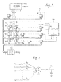
- the apparatus shown in Figure 1 has a front-end speech processing unit 100.
- Input speech signals s are divided into frames of, for example, 10 ms duration, and each frame is analysed to generate a plurality of parameters representing characteristics of that frame.
- One convenient measure is the energy content of successive frequency bands within the total spectrum of the speech, which can readily be generated by transform techniques or even by a bank of band-pass filters.
- Such feature extraction in general and spectral analysis in particular are well known techniques for speech processing and recognition and will not, therefore, be described further here.
- N may be 16 or 32.
- the vectors X generated for successive frames of speech form a temporal sequence of vectors.
- the purpose of the remainder of the apparatus is to identify patterns (and hence phonemes, words, etc) in this sequence. Although it is described in the context of speech, it will be appreciated that recognition of patterns in other temporal sequences of vectors is also possible.
- the apparatus also has elements or units 101 set out in a two-dimensional array. The input to the array is supplied simultaneously to all elements of the array.
- Each element has a single (scalar) analogue output, denoted by ⁇ i where i is an index number denoting the particular element.
- this function is the dot product, ie
- the dot (.) is used to signify a vector dot product and star (*) to indicate a product of scalar quantities.
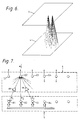
- This function may be realised by an element of the form illustrated in Figure 2, where an amplifier AA forms an output voltage proportional to the sum of the currents in weighting resistors R j whose values correspond to the reciprocals of stored weights w ij (though a practical element will be more complex owing to the need to adjust the weights).
- Elements such as shown in Figure 2 are often called neurons, by analogy with biological systems, and this term is used in this description.
- an auxiliary computer 104 which has access to the outputs ⁇ i of the neurons and is able to change their weight vectors w i .
- speech is fed to the input processor and each vector X supplied to the array is dealt with in that:
- training may take the following form:
- a modification to this process avoids the necessity of explicitly identifying the most excited neuron, by applying the modification to neurons within the neighbourhood surrounding every neuron, but varying the amount of adjustment according to a non-linear function of the output of the neuron defining the neighbourhood - eg the output raised to a high power m.
- the rate constant k may be a function of the distance of the neuron in question from the neuron defining the neighbourhood; and it is preferred to reduce the size of the neighbourhood as training progresses.
- W i .X may be written as:
- * cos ⁇ where ⁇ is the angle between the two vectors in N-dimensional space. If W i is normalised to unity magnitude, we have ⁇ i
- the array After the array has been successfully trained, the array is ordered in terms of sound quality and the receipt of an input signal vector by the array will result in each neuron generating an output signal whose degree of excitation varies with the similarity between the input vector and the corresponding weight vector. For any given input vector, only a small group of neurons will generate output signals of any significant magnitude and these will be grouped together within the array. If the array could be viewed from above, and the neurons' output seen as lights of variable intensity, the application of a single input vector would cause a bright "blob" in one part of the array formed by the output signals from the grouped neural elements, the position of the blob being characteristic of the type of sound represented by the input vector.
- the relationship between the array positions of the "most excited neurons" for given input vectors will (perhaps surprisingly) tend to map topologically to the relative positions in "pattern" space of those input vectors (that is, in an N-dimensional perceptual space where N is the "inherent dimensionality" of the input data).
- Vowels for example, seem to be well represented by a 2-dimensional space; these types of speech data thus have an inherent dimensionality of 2 and are well mapped onto a 2-dimensional neural array.
- a recognition apparatus may include the auxiliary computer for training, or retraining, but may lack such a computer if it can be loaded with the weights already learned by another machine.
- trajectory is independent of any time warp (viz variation in rate) of the utterance and so conventional pattern recognition techniques can be used to determine from the trajectory the nature of the original utterance (although the intensity profile along the trajectory is related to time warp and loudness).
- Figure 1 shows such a recognition unit 110.
- firings a distinct succession of high-output neurons, sometimes called "firings". Note however that use of the term firing does not necessarily imply a thresholding process.
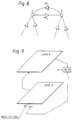
- the preferred method for achieving recognition is, as shown by the example in Figure 5, to provide a plurality of arrays; p second layers 2 are arranged in series with the first layer 1.
- the idea behind the stack of neural arrays is to use the trajectory produced on the bottom layer as input to the second layer, which is so connected to the first layer that it produces a more compressed trajectory therein, and so on, up through the layers of the stack until a word or even a sequence of words generates a trajectory on a high layer which is so short that it can be associated with just one or a small group of neurons.
- the final recognition stage 110′ then serves simply to identify that one or small localised group of neurons having the largest output. This neuron can be labelled explicitly with the appropriate utterance.
- FIG. 6 A solution avoiding both of these problems is illustrated in Figure 6.
- the input vector to a neuron in a layer 3 and having co-ordinates (x,y) is derived from the outputs of a fairly small number of neurons in a layer 4 which lie within a small circle whose centre has the same coordinates (x,y).
- the circular regions in the layer 4 overlap, so that the inputs to neurons within a small locality in the layer 3 will be very similar, and the array in the layer 3 will become ordered after training in a similar way to an array which has a global input vector, except that the ordering will be local rather than global.
- connection strategy overcomes the problem of the numbers of interconnections. If layer 3 contains 10,000 neurons each of which is connected to 100 neuron outputs in the previous layer, then 106 interconnections would be needed.
- the developed neural array preferably has decaying persistence built into each element and this causes the trajectory of excited elements to be partially "frozen” on the array, such that at one instant in time the most recently stimulated element on the trajectory is most excited and all the other elements along the trajectory are also excited but with decreasing intensity.
- the system described is able to transform a sequence of pattern vectors representing a process with variable time warp, to a single pattern of element excitation in the neural array. This single pattern is time warp independent if the excitation intensity profile along the array is ignored.
- the patterns of excitation in the array can be expressed as a vector in many other ways, but, for example, could be a vector whose elements were the co-ordinates of the z most intensely excited elements in the array where z is some fixed number.
- Another way in which the inputs to the neural elements of one layer may be derived from the outputs of the previous layer is as follows:
- the outputs of all the neurons in the lower layer are thresholded with a threshold which has a value such that only those elements which lie approximately on the path of trajectories of excited elements in the lower layer produce an output.
- a threshold which has a value such that only those elements which lie approximately on the path of trajectories of excited elements in the lower layer produce an output.
- another form of non-linearity is made to act on the outputs of all elements in the lower layer.
- the output of each element may be raised to the power m where m is greater than one. Imposing this type of non-linearity on the element outputs has the effect of accentuating the difference in excitation between elements which lie in the vicinity of a trajectory and those that do not lie near a trajectory.
- the first layer trajectory would cover several words.
- the numbers of allowable permutations of even a few words taken out of a moderately sized vocabulary is immense and so there would be an enormous number of different trajectories, each of which would need to cause strong firing of a distinct neuron in the subsequent layer.
- the number of neurons required in the next layer would be unrealisable, either artificially or biologically.
- certain concepts of grammar are built into the system.
- One method which we have devised for achieving this recognises that some trajectories are more likely to occur than others, and therefore biases the trajectories towards those preferred trajectories by cross-coupling within the layer.
- the outputs of neurons in this array are fed after weighting (in multipliers 7) by stored factors of ⁇ ij into the second part 6, an array of adding nodes 9 which sums e i for each neuron with the weighted outputs e i,j , of the q neurons within a neighbourhood of the neuron in the previous array to give an overall neuron excitation of e ′ i : where e i,j is the excitation of the j th one of the q neighbouring neurons.
- the factors ⁇ ij comprise grammar weights which tend to guide utterance trajectories along likely paths in the array, these paths being those expected in conventional speech. This therefore makes the shape of the path less dependent on speaker variation or background noise.
- the first part may be considered to be a topologically ordered array of "receptor neurons” while the second part 6 may be considered to be an array of "ganglion" neurons. It should be noted that the second part 6 is not ordered in the normal sense. Note that in Figure 7, e n ij is used rather than e n-1 ij . Whether this is possible in practice will depend on the delays in the system.
- the system works as follows: assume for the moment that all the weights, ⁇ , between ganglions and receptors are zero. Say that a common sequence of excitation in the receptor array 5 is neuron R1 followed by neuron R2 (R denotes receptor and G ganglion). Excitation of R1 followed by R2 in the receptor array causes excitation of nodes G1 and G2 in the ganglion array 6. If the second input pattern to the receptor array 5 is corrupted in some way such that neuron R4 is fired instead of R2, then node G2 in the ganglion array will be correspondingly excited. Thus the system is unable to combat corruption or noise in the input patterns.
- the receptor to ganglion connection weights are learnt from the application of a large number of pattern sequences.
- FIG. 8 An alternative embodiment with means for introducing grammar into the system is illustrated schematically in Figure 8.
- neurons i, j of each array are coupled by weights ⁇ i,j , ⁇ j,i with their immediately surrounding neighbours.
- ⁇ By suitably setting the values ⁇ , a trajectory within a particular layer will follow a preferential route since the moderate stimulation of a neuron will cause large stimulating signals to be fed via the neural interconnections having large weights to the neighbouring neurons which will respond to these signals when processing the next input vector.
- the trajectory produced by an utterance in the first layer 1 will be substantially continuous. However, not all trajectories will be fully continuous and will instead consist of a series of separated relatively short segments. This might occur, for example, in the first layer, as it receives a vowel-stop consonant-vowel (V1 - C - V2) utterance.
- FIG. 9 A scheme is shown in Figure 9 in which the global firing pattern in a higher layer 9 is fed back and presented as an input vector to the layer 8 below along with the ordinary input vector.
- the scheme would operate on the (V1-C) and (C-V2) trajectories in the following way.
- the occurrence of the V1-C trajectory on the layer 8 causes a compressed trajectory to occur on the layer 9 due to the forward inter-layer connection.
- the delay 10 is shown as a separate element in the system but in reality it is expected to be implicit in the neural arrays themselves.
- F actually gets to the input of the layer 8 at the same time as the vector X representing the start of V2.
- the input vector X with null feedback vector would only cause weak excitation of the (C-V2) trajectory, as would a null input vector appended by an active feedback vector.
- the joint occurrence of an active feedback, F, and input X should cause high excitation of the C-V2 trajectory, since this is the input on which the system has been trained.
- This feedback also has the result that recognition of a particular word will predispose lower layers to recognise the primitive sounds associated with the anticipated next word.
- the purpose of this predispositions to aid recognition of ill defined input patterns.
- the operation of the system can be understood by considering a higher layer in which words are recognised and a lower layer in which phonemes are recognised. Say that a particular word has just been recognised in the word layer. This information is fed back and forms part of the input to the phoneme layer at the same time as the patterns corresponding to the phoneme of the next word are coming in.
- the phoneme layer is trained on the combination of feedback pattern plus input pattern and so both are necessary to cause full excitation of the phoneme array neurons associated with the phoneme in the second word.
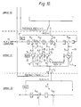
- Figure 10 illustrates the architecture of a neural array structure having m neural or computing elements N1 ... N m , each of which is associated with a respective local RAM 20. Each RAM stores synaptic weights for the associated neural element.
- x is the input vector from the layer 24 below (or, for the first layer, the input vector)
- y r is the feedback vector from the layer 23 above
- ⁇ , w ir and C ir are the persistence weight and feedforward and feedback synaptic weights respectively contained in the local RAM.
- Operation of the system is as follows: Assume that the neurons N1 to N m have just finished computing their respective outputs ⁇ n-1 1 to ⁇ n-1 m which are stored in respective accumulators of the neural elements (not shown) and switch S2 set at position b . Switches S31 to S 3m are set to position a so that the neural outputs are loaded into the storage elements (T) of the output bus 24of layer 21. At the same instant switches S11 to S 1m are set to position b so that each neuron's output ⁇ n-1 i is connected to its input along the persistence path 25 and the accumulators are cleared.
- Switches S31 to S 3m of all the arrays now move to position b and switches S11 to S 1m switch to position a such that the first value, x1, stored on the feed forward bus of layer 22 is applied to the inputs of all neurons in layer 21 simultaneously while the appropriate synaptic weights w11 to w m1 are drawn from each neuron's local RAM. (At the same time, the first value on the feed forward bus of layer 21 is being applied to the inputs of neurons in layer 23 and so on, up through the stack of arrays).
- the feed forward bus 24 on each array is then "clocked" along one place so that the next value, x2, from the array is applied to all neurons in the next array, and the next partial output x2.w i2 is computed and added to the previous partial output in the accumulator of each neuron. This process is continued until the feed forward bus has been completely circulated.
- Next switch S2 moved to position a and the process is repeated with y1 to y m in turn as inputs. These are values fedback from the output bus of a higher layer along feedback path 26.
- each neuron has computed a new output value ⁇ n i stored in the accumulator and the entire process re-commences.
- the non-linearity processor 27 in series with the output bus 24 of each array is optional. Its function, if included, is to threshold, or raise to a power, the values stored on the bus.
- each storage element, T, in the output bus 24 will consist of an eight bit SISO shift register.
- Figure 10 tacitly assumes that the output of all the neurons of an array form the input for the next layer. As explained above, this is often unrealistic; however, the architecture of Figure 10 can readily be modified by connecting groups of neurons to separate buses corresponding to the local groupings illustrated in Figure 4.
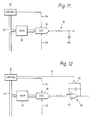
- FIG 11 illustrates a hybrid analogue/digital realisation of a computing element which may be used in the arrangement of Figure 10.
- all synaptic weights are stored digitally in the RAM 20 which is addressed from a control circuit 30 via an address bus 31.
- Digital values from the RAM 20 are fed to a multiplying digital-to-analogue converter (DAC) 32 which also receives via an input line 33 the analogue input signal from the respective switch S11-S 1m .
- Operation of the DAC 32 is controlled by clock signals generated by the control circuit 30 and fed along a control line 34.
- the DAC 32 may be realised for example by a switched R-2R ladder or ramp comparator.
- the accumulator 35 associated with the computing element is formed by a R-C leaky integrator.
- each storage element T in the serial bus will be realised by a single stage clocked analogue shift register to which clock signals are supplied from the control circuit 30.
- This shift register could be a charge-coupled device, a bucket brigade line or sample and hold circuit.
- all signal values in this system will be represented by analogue voltages and be circulated on the serial output bus 24 and feedback paths in pulse amplitude modulation.
- Figure 12 illustrates a modification of the Figure 11 example in which the accumulator 35 is formed by a resettable analogue integrator with a switch 36 controlled via a control line 37 by the control circuit 30.
- Figure 13 illustrates a pure analogue realisation of a neural element.
- the serial bus structure of Figure 10 is abandoned. It is assumed that the outputs of neurons in one layer are physically connected to the inputs of neurons in the next layer.
- the voltages representing each element of a pattern vector applied to the bottom array in the stack are applied in parallel to the inputs of each neuron in that array, i.e. if the pattern vector has 30 elements, then each neuron in the bottom array must have 30 parallel inputs.
- the analogue circuitry enables the synaptic weight to be updated in real time without the use of an auxiliary computer.
- the system is entirely self-sufficient.
- the signal inputs to the neuron are x1 whilx N .
- the magnitude of the resistance R DSj is controlled by the voltage applied to the gate of transistor T 2j which in turn is controlled by the current flowing through T 1j .
- the current through T 1j depends on the amount of charge stored on its gate which in turn is supplied via T 3j from the signal input voltage x j .
- the ordering algorithm for the array only synaptic weight vectors of those neurons which are in the neighbourhood of the most strongly excited neurons should be modified. This is achieved in this circuit by controlling the flow of current to the gate of T 1j by using the sum (from a summation unit A) of the output of the neuron and the outputs of adjacent neurons in the array (ie those in whose neighbourhoods the neuron lies) to control the voltage on the gate T 3j which controls the flow charge onto the gate of T 1j .
- the factor L in the previous expression is the aggregate excitation of all the neurons in a particular part of the array.
Landscapes
- Engineering & Computer Science (AREA)
- Physics & Mathematics (AREA)
- Theoretical Computer Science (AREA)
- Health & Medical Sciences (AREA)
- General Physics & Mathematics (AREA)
- Multimedia (AREA)
- Computational Linguistics (AREA)
- Artificial Intelligence (AREA)
- Evolutionary Computation (AREA)
- Life Sciences & Earth Sciences (AREA)
- Biomedical Technology (AREA)
- Biophysics (AREA)
- Computing Systems (AREA)
- General Engineering & Computer Science (AREA)
- Data Mining & Analysis (AREA)
- Acoustics & Sound (AREA)
- General Health & Medical Sciences (AREA)
- Molecular Biology (AREA)
- Computer Vision & Pattern Recognition (AREA)
- Human Computer Interaction (AREA)
- Mathematical Physics (AREA)
- Software Systems (AREA)
- Audiology, Speech & Language Pathology (AREA)
- Neurology (AREA)
- Databases & Information Systems (AREA)
- Image Analysis (AREA)
- Electrically Operated Instructional Devices (AREA)
Claims (18)
- Appareil de reconnaissance de configurations destiné à une reconnaissance de parole ou de toute configuration qui possède des particularités caractérisantes équivalentes qui permettent une reconnaissance d'une manière analogue, comprenant:- une entrée de réception d'une séquence temporelle de vecteurs (Xn) de signaux d'entrée;- des moyens de mémoire (R₁, ... Rn) pour mémoriser une série de vecteurs (Wi) de référence;- un réseau incluant une série d'éléments (101) de comparaison agencés en fonctionnement de manière à recevoir chacun chaque vecteur d'entrée de la séquence temporelle et à engendrer pour chacun desdits vecteurs d'entrée, lorsque ledit vecteur d'entrée est actuellement à l'entrée, un signal de sortie (ηi n) indicatif du degré de similitude entre ledit vecteur actuel d'entrée et un vecteur respectif parmi les vecteurs de référence qui viennent du moyen de mémoire, caractérisé par:- un moyen de modification (115) pour produire pour chaque élément une sortie modifiée (ei n) qui dépend du signal de sortie (ei n-1) produit précédemment par cet élément à la suite de la comparaison entre le vecteur de référence pour cet élément et au moins le vecteur d'entrée immédiatement précédent (Xn-1) de la séquence temporelle; et- un moyen de reconnaissance (110) pour comparer à une information de configuration de référence une configuration définie par lesdites sorties modifiées, afin d'identifier une configuration correspondante dans ladite séquence temporelle.
- Appareil de reconnaissance de configurations selon la revendication 1, dans lequel le moyen de modification est agencé pour produire pour chaque élément une sortie modifiée qui est la somme de la sortie actuelle de cet élément pour un vecteur d'entrée actuel et d'une série de sorties précédentes de cet élément pour des vecteurs d'entrée précédents, chaque sortie précédente étant multipliée par une valeur choisie d'une manière telle que chacune de ces sorties antérieures est affectée d'une pondération qui est une fonction à décroissance monotone du temps qui s'est écoulé entre cette sortie précédente et la sortie du vecteur actuel.
- Appareil de reconnaissance de configurations selon la revendication 2, dans lequel la fonction à décroissance monotone est une exponentielle amortie et le signal modifié est donné par:

- Appareil de reconnaissance de configurations selon les revendications 1, 2, ou 3 dans lequel le moyen de mémoire contient des vecteurs de référence engendrés:- en appliquant à l'entrée une séquence d'apprentissage de vecteur de signaux;- pour chaque vecteur d'entrée:
en identifiant l'élément qui possède une sortie indiquant la plus grande similitude entre des vecteurs d'entrée et de référence; et
en appliquant aux vecteurs de référence de l'élément identifié et aux éléments qui sont situés, dans un espace de réseau notionnel, à l'intérieur d'un voisinage défini de cet élément un ajustement qui augmente la similitude entre ces vecteurs de référence et le vecteur de signal d'entrée,
grâce à quoi les vecteurs de référence représentent une application topologique des variations statistiques des vecteurs d'entrée de la séquence d'apprentissage. - Appareil de reconnaissance de configurations selon l'une des revendications 1, 2 ou 3, incluant un moyen de commande agencé en fonctionnement pour effectuer, pendant l'application d'une séquence d'apprentissage des signaux et des vecteurs à ladite entrée, les étapes consistant à:
- pour chaque vecteur d'entrée:
identifier l'élément dont la sortie indique la plus grande similitude entre les vecteurs d'entrée et de référence;
appliquer aux vecteurs de référence de l'élément identifié et aux éléments qui sont situés, dans un espace de réseau notionnel, à l'intérieur d'un voisinage défini de cet élément un ajustement qui augmente la similitude entre ces vecteurs de référence et le vecteur de signal d'entrée,
grâce à quoi les vecteurs de référence représentent une application topologique des variations statistiques des vecteurs d'entrée de la séquence d'apprentissage. - Appareil de reconnaissance de configurations selon l'une quelconque des revendications précédentes, incluant un moyen de production, pour chaque élément, d'une sortie modifiée de nouveau qui est la somme de la sortie modifiée de cet élément et d'une somme pondérée des sorties modifiées d'autres éléments choisis.
- Appareil de reconnaissance de configurations selon la revendication 6, dans lequel les pondérations employées pour former ladite somme pondérée ont été engendrées en appliquant à l'entrée une séquence d'apprentissage de vecteurs de signaux et en ajustant de façon itérative la valeur de la pondération à employer, entre chaque élément et chacun desdits autres éléments respectifs, d'une quantité qui est fonction du produit de sorties produites par ces deux éléments.
- Appareil de reconnaissance de configurations selon la revendication 6, incluant un moyen de commande agencé en fonctionnement pour ajuster de façon itérative, pendant qu'une séquence d'apprentissage de vecteurs de signaux est appliqué à l'entrée, la valeur de la pondération à employer, entre chaque élément et chacun desdits autres éléments respectifs, d'une quantité qui est fonction du produit de sorties produites par ces deux éléments.
- Appareil de reconnaissance de configurations selon l'une quelconque des revendications précédentes, dans lequel ladite sortie modifiée ou lesdites sorties modifiées de nouveau sont soumises à une opération linéaire de manière à accroître des sorties indicatives d'une similitude élevée par rapport aux sorties indicatives d'une similitude moindre.
- Appareil de reconnaissance de configurations selon l'une quelconque des revendications précédentes, dans lequel le moyen de reconnaissance comprend au moins un autre réseau de tels éléments de comparaison qui inclut des vecteurs de référence mémorisés respectifs, chacun de ces éléments étant relié de façon à recevoir un groupe respectif des sorties modifiées (ou des sorties modifiées de nouveau) du réseau ou d'un réseau précédent de façon à engendrer un signal de sortie indicatif de la similitude entre un vecteur de référence respectif de cet élément et ledit groupe de sorties.
- Appareil de reconnaissance de configurations selon la revendication 10, agencé pour envoyer en rétroaction les signaux de sortie engendrés par un ou plusieurs des réseaux de façon à modifier un vecteur suivant de signal d'entrée, ou un groupe suivant de signaux, envoyés au réseau précédent ou à un réseau précédent.
- Appareil de reconnaissance de configurations selon l'une quelconque des revendications précédentes, dans lequel les vecteurs de référence sont normalisés d'une manière telle que l'élément qui produit une sortie indicative de la plus grande similitude entre le vecteur d'entrée et son vecteur de référence ne varie pas lors de variations d'amplitude du vecteur d'entrée.
- Appareil de reconnaissance de configurations selon la revendication 12, dans lequel un élément de comparaison est apte à produire une sortie qui est le produit scalaire du vecteur de référence respectif de cet élément par le vecteur d'entrée, ou qui est une fonction de ce produit.
- Appareil de reconnaissance de configurations destiné àune reconnaissance de parole ou de toute configuration qui possède des particularités caractérisantes équivalentes qui permettent une reconnaissance d'une manière analogue, comprenant:- une entrée de réception d'une séquence temporelle de vecteurs de signaux d'entrée;- un réseau qui comprend une série d'éléments de comparaison, chaque élément possédant une sortie et une série d'entrées reliées en parallèle avec les entrées des autres éléments de comparaison d'une manière telle que chaque élément peut recevoir chaque vecteur d'entrée;- un moyen de mémoire pour mémoriser une série de vecteurs de référence; chaque élément de comparaison étant agencé en fonctionnement pour produire à sa sortie un signal indicatif de la similitude entre chaque vecteur d'entrée et un vecteur respectif parmi les vecteurs de référence, caractérisé en ce que chaque élément est apte à produire une sortie qui est le produit scalaire, ou une fonction de ce produit, du vecteur d'entrée et de référence modifiés en fonction du signal de sortie produit par cet élément par suite d'une comparaison entre le vecteur de référence respectif de cet élément et au moins le vecteur d'entrée immédiatement précédent et les vecteurs de référence sont normalisés d'une manière telle que chaque élément qui produit une sortie indicative de la similitude la plus grande entre le vecteur d'entrée et son vecteur de référence ne varie pas lors de variations d'amplitude du vecteur d'entrée.
- Appareil de reconnaissance de configurations selon la revendication 13 ou 14, dans lequel chaque élément comprend, pour recevoir un vecteur de signaux à N dimensions, une série N de sections, chaque section incluant:- une entrée;- un trajet à conduction variable entre cette entrée et un noeud actuel de sommation pour former une sortie;- un transistor d'accumulation qui consiste en un transistor à effet de champ à grille isolée agencé pour commander la conductivité du trajet en fonction de la quantité de charge accumulée sur la grille du transistor d'accumulation; et- un moyen d'ajustement de ladite charge accumulée en fonction de la sortie de l'élément et des sorties d'éléments voisins.
- Appareil de reconnaissance de configurations selon la revendication 15, dans lequel le trajet conducteur est formé par un autre transistor et le transistor d'accumulation est relié de façon à fournir une partie du courant venant d'une source unique constante de courant afin de commander la conductivité de l'autre transistor, grâce à quoi la somme algébrique de la conductivité de tous lesdits autres transistors d'un élément est sensiblement constante.
- Un appareil de reconnaissance de la parole comprenant un appareil de reconnaissance de configurations selon l'une quelconque des revendications précédentes, incluant un moyen de traitement de la parole qui peut être mis en oeuvre pour analyser une entrée de parole dans chaque période d'échantillonnage d'une séquence temporelle de périodes d'échantillonnage et pour engendrer, pour chacune de ces périodes, une série de paramètres représentatifs de l'entrée de parole dans ladite période, lesdits paramètres formant les composants de chacun des vecteurs de signaux d'entrée de la séquence temporelle en tant qu'entrée à l'appareil de reconnaissance de configurations.
- Un appareil de reconnaissance de la parole selon la revendication 17, dans lequel la durée des périodes d'échantillonnage est choisie suffisamment brève pour que les valeurs de paramètres varient lentement par rapport à la fréquence d'échantillonnage.
Applications Claiming Priority (3)
| Application Number | Priority Date | Filing Date | Title |
|---|---|---|---|
| GB8720387 | 1987-08-28 | ||
| GB878720387A GB8720387D0 (en) | 1987-08-28 | 1987-08-28 | Matching vectors |
| PCT/GB1988/000710 WO1989002134A1 (fr) | 1987-08-28 | 1988-08-26 | Appareil de reconnaissance de reseau |
Publications (2)
| Publication Number | Publication Date |
|---|---|
| EP0333798A1 EP0333798A1 (fr) | 1989-09-27 |
| EP0333798B1 true EP0333798B1 (fr) | 1995-05-24 |
Family
ID=10623002
Family Applications (1)
| Application Number | Title | Priority Date | Filing Date |
|---|---|---|---|
| EP88907744A Expired - Lifetime EP0333798B1 (fr) | 1987-08-28 | 1988-08-26 | Appareil de reconnaissance de formes |
Country Status (9)
| Country | Link |
|---|---|
| US (1) | US5175794A (fr) |
| EP (1) | EP0333798B1 (fr) |
| JP (1) | JPH02501167A (fr) |
| AT (1) | ATE123165T1 (fr) |
| CA (1) | CA1310419C (fr) |
| DE (1) | DE3853880T2 (fr) |
| GB (2) | GB8720387D0 (fr) |
| HK (1) | HK121296A (fr) |
| WO (1) | WO1989002134A1 (fr) |
Families Citing this family (23)
| Publication number | Priority date | Publication date | Assignee | Title |
|---|---|---|---|---|
| FI881007A0 (fi) * | 1988-03-04 | 1988-03-04 | Teuvo Kohonen | Foerfarande foer adaptiv avlaesning av kvantiserade signaler. |
| GB2245401A (en) * | 1989-11-01 | 1992-01-02 | Hughes Aircraft Co | Neural network signal processor |
| GB8929146D0 (en) * | 1989-12-22 | 1990-02-28 | British Telecomm | Neural networks |
| JP3260357B2 (ja) | 1990-01-24 | 2002-02-25 | 株式会社日立製作所 | 情報処理装置 |
| US5794190A (en) * | 1990-04-26 | 1998-08-11 | British Telecommunications Public Limited Company | Speech pattern recognition using pattern recognizers and classifiers |
| GB9009425D0 (en) * | 1990-04-26 | 1990-06-20 | British Telecomm | Pattern recognition |
| KR930009066B1 (ko) * | 1990-08-18 | 1993-09-22 | 정호선 | 다층신경회로망 및 그 회로설계방법 |
| US5809461A (en) * | 1992-03-30 | 1998-09-15 | Seiko Epson Corporation | Speech recognition apparatus using neural network and learning method therefor |
| JPH05335967A (ja) * | 1992-05-29 | 1993-12-17 | Takeo Miyazawa | 音情報圧縮方法及び音情報再生装置 |
| JPH07210190A (ja) * | 1993-12-30 | 1995-08-11 | Internatl Business Mach Corp <Ibm> | 音声認識方法及びシステム |
| US5524169A (en) * | 1993-12-30 | 1996-06-04 | International Business Machines Incorporated | Method and system for location-specific speech recognition |
| JP3399674B2 (ja) * | 1994-12-19 | 2003-04-21 | エヌイーシーインフロンティア株式会社 | 画面制御装置とその方法 |
| US6151592A (en) * | 1995-06-07 | 2000-11-21 | Seiko Epson Corporation | Recognition apparatus using neural network, and learning method therefor |
| JP3697748B2 (ja) * | 1995-08-21 | 2005-09-21 | セイコーエプソン株式会社 | 端末、音声認識装置 |
| US5950162A (en) * | 1996-10-30 | 1999-09-07 | Motorola, Inc. | Method, device and system for generating segment durations in a text-to-speech system |
| US5927988A (en) * | 1997-12-17 | 1999-07-27 | Jenkins; William M. | Method and apparatus for training of sensory and perceptual systems in LLI subjects |
| US6208963B1 (en) * | 1998-06-24 | 2001-03-27 | Tony R. Martinez | Method and apparatus for signal classification using a multilayer network |
| US6304865B1 (en) | 1998-10-27 | 2001-10-16 | Dell U.S.A., L.P. | Audio diagnostic system and method using frequency spectrum and neural network |
| US6178402B1 (en) | 1999-04-29 | 2001-01-23 | Motorola, Inc. | Method, apparatus and system for generating acoustic parameters in a text-to-speech system using a neural network |
| US7996212B2 (en) * | 2005-06-29 | 2011-08-09 | Fraunhofer-Gesellschaft Zur Foerderung Der Angewandten Forschung E.V. | Device, method and computer program for analyzing an audio signal |
| US20080147579A1 (en) * | 2006-12-14 | 2008-06-19 | Microsoft Corporation | Discriminative training using boosted lasso |
| EP2477141B1 (fr) * | 2011-01-12 | 2013-07-03 | Fujitsu Limited | Noed de processeur, réseau neuronal artificiel et procédé de fonctionnement d'un réseau neuronal artificiel |
| JP6708146B2 (ja) * | 2017-03-03 | 2020-06-10 | 株式会社デンソー | ニューラルネットワーク回路 |
Family Cites Families (12)
| Publication number | Priority date | Publication date | Assignee | Title |
|---|---|---|---|---|
| US3287649A (en) * | 1963-09-09 | 1966-11-22 | Research Corp | Audio signal pattern perception device |
| GB1192554A (en) * | 1966-08-13 | 1970-05-20 | Emi Ltd | Improvements relating to Pattern Recognition Devices |
| US3845471A (en) * | 1973-05-14 | 1974-10-29 | Westinghouse Electric Corp | Classification of a subject |
| GB1545117A (en) * | 1976-05-25 | 1979-05-02 | Nat Res Dev | Comparison apparatus eg for use in character recognition |
| IT1118355B (it) * | 1979-02-15 | 1986-02-24 | Cselt Centro Studi Lab Telecom | Sistema di interconnessione tra processori |
| US4254474A (en) * | 1979-08-02 | 1981-03-03 | Nestor Associates | Information processing system using threshold passive modification |
| JPS58129684A (ja) * | 1982-01-29 | 1983-08-02 | Toshiba Corp | パタ−ン認識装置 |
| US4816993A (en) * | 1984-12-24 | 1989-03-28 | Hitachi, Ltd. | Parallel processing computer including interconnected operation units |
| JPS622805A (ja) * | 1985-06-26 | 1987-01-08 | 日立電線株式会社 | 光フアイバ複合架空地線の架線方法 |
| JPH0634236B2 (ja) * | 1985-11-02 | 1994-05-02 | 日本放送協会 | 階層型情報処理方法 |
| US4773024A (en) * | 1986-06-03 | 1988-09-20 | Synaptics, Inc. | Brain emulation circuit with reduced confusion |
| US4805225A (en) * | 1986-11-06 | 1989-02-14 | The Research Foundation Of The State University Of New York | Pattern recognition method and apparatus |
-
1987
- 1987-08-28 GB GB878720387A patent/GB8720387D0/en active Pending
-
1988
- 1988-08-26 DE DE3853880T patent/DE3853880T2/de not_active Expired - Fee Related
- 1988-08-26 US US07/359,746 patent/US5175794A/en not_active Expired - Fee Related
- 1988-08-26 AT AT88907744T patent/ATE123165T1/de not_active IP Right Cessation
- 1988-08-26 EP EP88907744A patent/EP0333798B1/fr not_active Expired - Lifetime
- 1988-08-26 CA CA000575745A patent/CA1310419C/fr not_active Expired - Fee Related
- 1988-08-26 JP JP63507221A patent/JPH02501167A/ja active Pending
- 1988-08-26 GB GB8909642A patent/GB2215503B/en not_active Expired - Fee Related
- 1988-08-26 WO PCT/GB1988/000710 patent/WO1989002134A1/fr active IP Right Grant
-
1996
- 1996-07-11 HK HK121296A patent/HK121296A/xx not_active IP Right Cessation
Non-Patent Citations (8)
| Title |
|---|
| British Telecom Technology Journal, vol. 6, no. 2, April 1988, G.D. Tattersall et al.: "Neural arrays for speech recognition", pages 140-163, see whole document * |
| Electronics Letters, vol. 4, no. 20, 4 Oct. 1968, I. Aleksander et al.: "Microcicuit learning nets: improved recognition by means of pattern feedback", pages 425-426, see fig. 1 * |
| IEEE Journal of Solid-state Circuit, vol. SC-1, no. 2, Dec. 1966, IEEE, (New York, US), J.W. Mc Connel et al.: "MOS adaptive memory elements as weights in an adaptive pattern classifier", pages 94-99, see page 95, par.: "Adaptive element" * |
| IEEE Proceedings of the 6th International Conference on Pattern Recognition, 19-22 Oct. 1982, Munich, IEEE, (New York, US), T. Kohonen: "Clustering, taxonomy and topological maps of patterns", pages 114-128, see p 114 par.:"On the representation of complex empirical data"; p.116, right-hand column, line 22-p.119, left-hand column, line 35, p.123, par.:"Formation of phoneme maps"; figure 4, cited in the application * |
| IEEE Transactions on Computers, vol. C-20, no. 9, Sept. 1971, IEEE, (New york, US), L.C.W.Pols: "Real-time recognition of spoken words", pages 972-978, see p. 975, right-hand column, lines 28-32 * |
| L'Electricitè Electronique Moderne, vol. 42, no. 265, June/July 1972, B.H. Marin:" Le neurone cybernètique", pages 21-25, see p.22, left-hand column, lines 16-23; fig. 17a; fig.20: "Contrôle-rétroaction" * |
| Pattern Recognition, volume 15, no. 6, 1982, Pattern Recognition Society, K. Fukushima et al.: Neocognitron: a new algorithm for pattern recognition tolerant of deformations and shifts in position", pages 455-469, see p.457, right-hand column, lines 8-16; p.464, par.5; fig.2-4,8 * |
| Transactions of the I.R.E., Professional Group on Information Theory, no. 4, Sept. 1954, B.G. Farley et al.: Simulation of self-organizing systems by digital computer", pages 76-84, see p. 80, lines 1-20 * |
Also Published As
| Publication number | Publication date |
|---|---|
| GB2215503A (en) | 1989-09-20 |
| EP0333798A1 (fr) | 1989-09-27 |
| GB8909642D0 (en) | 1989-06-14 |
| DE3853880T2 (de) | 1995-11-02 |
| JPH02501167A (ja) | 1990-04-19 |
| GB8720387D0 (en) | 1987-10-07 |
| ATE123165T1 (de) | 1995-06-15 |
| HK121296A (en) | 1996-07-19 |
| DE3853880D1 (de) | 1995-06-29 |
| US5175794A (en) | 1992-12-29 |
| CA1310419C (fr) | 1992-11-17 |
| GB2215503B (en) | 1992-02-05 |
| WO1989002134A1 (fr) | 1989-03-09 |
Similar Documents
| Publication | Publication Date | Title |
|---|---|---|
| EP0333798B1 (fr) | Appareil de reconnaissance de formes | |
| Pal et al. | Multilayer perceptron, fuzzy sets, classifiaction | |
| EP0623914B1 (fr) | Système de reconnaissance de mots isolés indépendant du locuteur utilisant un réseau de neurones | |
| US6009418A (en) | Method and apparatus for neural networking using semantic attractor architecture | |
| WO2018194960A1 (fr) | Apprentissage et reconnaissance de machine multi-étage | |
| US5588091A (en) | Dynamically stable associative learning neural network system | |
| US5067095A (en) | Spann: sequence processing artificial neural network | |
| US11188815B2 (en) | Weight shifting for neuromorphic synapse array | |
| US5446829A (en) | Artificial network for temporal sequence processing | |
| Bodenhausen et al. | The tempo 2 algorithm: Adjusting time-delays by supervised learning | |
| Tavanaei et al. | Training a hidden Markov model with a Bayesian spiking neural network | |
| CN113962371B (zh) | 一种基于类脑计算平台的图像识别方法及系统 | |
| Chang et al. | Mandarin tone recognition by multi-layer perceptron | |
| Lawrence et al. | The Gamma MLP for speech phoneme recognition | |
| EP0453939B1 (fr) | Méthode d'apprentissage d'un système de traitement de données | |
| Lawrence et al. | The gamma MLP-using multiple temporal resolutions for improved classification | |
| JP2736361B2 (ja) | ニューラルネット構成方法 | |
| Mohanty et al. | Recognition of voice signals for Oriya language using wavelet neural network | |
| Bodenhausen et al. | Learning the architecture of neural networks for speech recognition. | |
| Ghosh et al. | Classification of spatiotemporal patterns with applications to recognition of sonar sequences | |
| JPH11265197A (ja) | 可変入力神経網を利用した音声認識方法 | |
| JPH04501327A (ja) | パターン伝達ニューラルネットワーク | |
| EP0484344A1 (fr) | Reconnaissance des structures | |
| Jou et al. | Mandarin syllables recognition based on one class one net neural network with modified selective update algorithm | |
| Kwan et al. | Second-order recurrent neural network for word sequence learning |
Legal Events
| Date | Code | Title | Description |
|---|---|---|---|
| PUAI | Public reference made under article 153(3) epc to a published international application that has entered the european phase |
Free format text: ORIGINAL CODE: 0009012 |
|
| 17P | Request for examination filed |
Effective date: 19890427 |
|
| AK | Designated contracting states |
Kind code of ref document: A1 Designated state(s): AT BE CH DE FR GB IT LI LU NL SE |
|
| 17Q | First examination report despatched |
Effective date: 19920304 |
|
| GRAA | (expected) grant |
Free format text: ORIGINAL CODE: 0009210 |
|
| RBV | Designated contracting states (corrected) |
Designated state(s): AT BE CH DE FR IT LI LU NL SE |
|
| AK | Designated contracting states |
Kind code of ref document: B1 Designated state(s): AT BE CH DE FR IT LI LU NL SE |
|
| PG25 | Lapsed in a contracting state [announced via postgrant information from national office to epo] |
Ref country code: LI Effective date: 19950524 Ref country code: CH Effective date: 19950524 Ref country code: AT Effective date: 19950524 |
|
| REF | Corresponds to: |
Ref document number: 123165 Country of ref document: AT Date of ref document: 19950615 Kind code of ref document: T |
|
| ITF | It: translation for a ep patent filed |
Owner name: JACOBACCI & PERANI S.P.A. |
|
| REF | Corresponds to: |
Ref document number: 3853880 Country of ref document: DE Date of ref document: 19950629 |
|
| PG25 | Lapsed in a contracting state [announced via postgrant information from national office to epo] |
Ref country code: LU Free format text: LAPSE BECAUSE OF NON-PAYMENT OF DUE FEES Effective date: 19950831 |
|
| REG | Reference to a national code |
Ref country code: CH Ref legal event code: PL |
|
| ET | Fr: translation filed | ||
| PLBE | No opposition filed within time limit |
Free format text: ORIGINAL CODE: 0009261 |
|
| STAA | Information on the status of an ep patent application or granted ep patent |
Free format text: STATUS: NO OPPOSITION FILED WITHIN TIME LIMIT |
|
| 26N | No opposition filed | ||
| PGFP | Annual fee paid to national office [announced via postgrant information from national office to epo] |
Ref country code: SE Payment date: 20010716 Year of fee payment: 14 |
|
| PGFP | Annual fee paid to national office [announced via postgrant information from national office to epo] |
Ref country code: NL Payment date: 20010719 Year of fee payment: 14 |
|
| PGFP | Annual fee paid to national office [announced via postgrant information from national office to epo] |
Ref country code: BE Payment date: 20010809 Year of fee payment: 14 |
|
| PGFP | Annual fee paid to national office [announced via postgrant information from national office to epo] |
Ref country code: FR Payment date: 20020708 Year of fee payment: 15 |
|
| PGFP | Annual fee paid to national office [announced via postgrant information from national office to epo] |
Ref country code: DE Payment date: 20020724 Year of fee payment: 15 |
|
| PG25 | Lapsed in a contracting state [announced via postgrant information from national office to epo] |
Ref country code: SE Free format text: LAPSE BECAUSE OF NON-PAYMENT OF DUE FEES Effective date: 20020827 |
|
| PG25 | Lapsed in a contracting state [announced via postgrant information from national office to epo] |
Ref country code: BE Free format text: LAPSE BECAUSE OF NON-PAYMENT OF DUE FEES Effective date: 20020831 |
|
| BERE | Be: lapsed |
Owner name: BRITISH *TELECOMMUNICATIONS P.L.C. Effective date: 20020831 |
|
| PG25 | Lapsed in a contracting state [announced via postgrant information from national office to epo] |
Ref country code: NL Free format text: LAPSE BECAUSE OF NON-PAYMENT OF DUE FEES Effective date: 20030301 |
|
| EUG | Se: european patent has lapsed | ||
| NLV4 | Nl: lapsed or anulled due to non-payment of the annual fee |
Effective date: 20030301 |
|
| PG25 | Lapsed in a contracting state [announced via postgrant information from national office to epo] |
Ref country code: DE Free format text: LAPSE BECAUSE OF NON-PAYMENT OF DUE FEES Effective date: 20040302 |
|
| PG25 | Lapsed in a contracting state [announced via postgrant information from national office to epo] |
Ref country code: FR Free format text: LAPSE BECAUSE OF NON-PAYMENT OF DUE FEES Effective date: 20040430 |
|
| REG | Reference to a national code |
Ref country code: FR Ref legal event code: ST |
|
| PG25 | Lapsed in a contracting state [announced via postgrant information from national office to epo] |
Ref country code: IT Free format text: LAPSE BECAUSE OF NON-PAYMENT OF DUE FEES Effective date: 20050826 |