EP0333701A2 - Method for controlling and regulating an automotive engine - Google Patents
Method for controlling and regulating an automotive engine Download PDFInfo
- Publication number
- EP0333701A2 EP0333701A2 EP89890078A EP89890078A EP0333701A2 EP 0333701 A2 EP0333701 A2 EP 0333701A2 EP 89890078 A EP89890078 A EP 89890078A EP 89890078 A EP89890078 A EP 89890078A EP 0333701 A2 EP0333701 A2 EP 0333701A2
- Authority
- EP
- European Patent Office
- Prior art keywords
- speed
- memory
- component
- components
- engine
- Prior art date
- Legal status (The legal status is an assumption and is not a legal conclusion. Google has not performed a legal analysis and makes no representation as to the accuracy of the status listed.)
- Granted
Links
Images


Classifications
-
- F—MECHANICAL ENGINEERING; LIGHTING; HEATING; WEAPONS; BLASTING
- F02—COMBUSTION ENGINES; HOT-GAS OR COMBUSTION-PRODUCT ENGINE PLANTS
- F02D—CONTROLLING COMBUSTION ENGINES
- F02D31/00—Use of speed-sensing governors to control combustion engines, not otherwise provided for
- F02D31/001—Electric control of rotation speed
- F02D31/007—Electric control of rotation speed controlling fuel supply
- F02D31/009—Electric control of rotation speed controlling fuel supply for maximum speed control
-
- F—MECHANICAL ENGINEERING; LIGHTING; HEATING; WEAPONS; BLASTING
- F02—COMBUSTION ENGINES; HOT-GAS OR COMBUSTION-PRODUCT ENGINE PLANTS
- F02D—CONTROLLING COMBUSTION ENGINES
- F02D41/00—Electrical control of supply of combustible mixture or its constituents
- F02D41/30—Controlling fuel injection
- F02D41/38—Controlling fuel injection of the high pressure type
- F02D41/40—Controlling fuel injection of the high pressure type with means for controlling injection timing or duration
- F02D41/406—Electrically controlling a diesel injection pump
- F02D41/407—Electrically controlling a diesel injection pump of the in-line type
-
- F—MECHANICAL ENGINEERING; LIGHTING; HEATING; WEAPONS; BLASTING
- F02—COMBUSTION ENGINES; HOT-GAS OR COMBUSTION-PRODUCT ENGINE PLANTS
- F02B—INTERNAL-COMBUSTION PISTON ENGINES; COMBUSTION ENGINES IN GENERAL
- F02B3/00—Engines characterised by air compression and subsequent fuel addition
- F02B3/06—Engines characterised by air compression and subsequent fuel addition with compression ignition
-
- F—MECHANICAL ENGINEERING; LIGHTING; HEATING; WEAPONS; BLASTING
- F02—COMBUSTION ENGINES; HOT-GAS OR COMBUSTION-PRODUCT ENGINE PLANTS
- F02D—CONTROLLING COMBUSTION ENGINES
- F02D41/00—Electrical control of supply of combustible mixture or its constituents
- F02D41/02—Circuit arrangements for generating control signals
- F02D41/14—Introducing closed-loop corrections
- F02D41/1401—Introducing closed-loop corrections characterised by the control or regulation method
- F02D2041/1409—Introducing closed-loop corrections characterised by the control or regulation method using at least a proportional, integral or derivative controller
-
- F—MECHANICAL ENGINEERING; LIGHTING; HEATING; WEAPONS; BLASTING
- F02—COMBUSTION ENGINES; HOT-GAS OR COMBUSTION-PRODUCT ENGINE PLANTS
- F02D—CONTROLLING COMBUSTION ENGINES
- F02D41/00—Electrical control of supply of combustible mixture or its constituents
- F02D41/02—Circuit arrangements for generating control signals
- F02D41/14—Introducing closed-loop corrections
- F02D41/1401—Introducing closed-loop corrections characterised by the control or regulation method
- F02D2041/1413—Controller structures or design
- F02D2041/1422—Variable gain or coefficients
-
- F—MECHANICAL ENGINEERING; LIGHTING; HEATING; WEAPONS; BLASTING
- F02—COMBUSTION ENGINES; HOT-GAS OR COMBUSTION-PRODUCT ENGINE PLANTS
- F02D—CONTROLLING COMBUSTION ENGINES
- F02D2250/00—Engine control related to specific problems or objectives
- F02D2250/12—Timing of calculation, i.e. specific timing aspects when calculation or updating of engine parameter is performed
-
- Y—GENERAL TAGGING OF NEW TECHNOLOGICAL DEVELOPMENTS; GENERAL TAGGING OF CROSS-SECTIONAL TECHNOLOGIES SPANNING OVER SEVERAL SECTIONS OF THE IPC; TECHNICAL SUBJECTS COVERED BY FORMER USPC CROSS-REFERENCE ART COLLECTIONS [XRACs] AND DIGESTS
- Y02—TECHNOLOGIES OR APPLICATIONS FOR MITIGATION OR ADAPTATION AGAINST CLIMATE CHANGE
- Y02T—CLIMATE CHANGE MITIGATION TECHNOLOGIES RELATED TO TRANSPORTATION
- Y02T10/00—Road transport of goods or passengers
- Y02T10/10—Internal combustion engine [ICE] based vehicles
- Y02T10/40—Engine management systems
Landscapes
- Engineering & Computer Science (AREA)
- Chemical & Material Sciences (AREA)
- Combustion & Propulsion (AREA)
- Mechanical Engineering (AREA)
- General Engineering & Computer Science (AREA)
- Electrical Control Of Air Or Fuel Supplied To Internal-Combustion Engine (AREA)
- Combined Controls Of Internal Combustion Engines (AREA)
- Output Control And Ontrol Of Special Type Engine (AREA)
- Control Of Throttle Valves Provided In The Intake System Or In The Exhaust System (AREA)
- Control Of Velocity Or Acceleration (AREA)
Abstract
Description
Die Erfindung bezieht sich auf ein Verfahren zum Steuern und Regeln einer Brennkraftmaschine eines Fahrzeuges, bei welchem in Abhängigkeit von Betriebsgrößensignalen, wie der Drehzahl, der Fahrpedalstellung, der Motortemperatur etc. in einer Recheneinrichtung ein Ausgangssignal errechnet und dieses zur Steuerung eines elektromechanischen Stellgliedes für die Kraftstoff- und/oder Luftmenge, insbesondere für eine Einspritzpumpe oder Pumpedüsen eines Dieselmotors herangezogen wird, wobei die P-, I-und D-Anteile eines Drehzahlregelsignales getrennt ermittelt und sodann addiert werden und das erhaltene Summensignal nach allfälliger Korrektur und/oder Begrenzung dem Stellglied zugeführt wird, sowie auf eine Vorrichtung zur Durchführung dieses Verfahrens.The invention relates to a method for controlling and regulating an internal combustion engine of a vehicle, in which an output signal is calculated in a computing device as a function of operating variable signals, such as the speed, the accelerator pedal position, the engine temperature, and this is used to control an electromechanical actuator for the fuel - and / or air volume, in particular for an injection pump or pump nozzles of a diesel engine, the P, I and D components of a speed control signal being determined separately and then added and the sum signal obtained, after any correction and / or limitation, being fed to the actuator is, as well as an apparatus for performing this method.
Elektronischen Reglern von Kraftfahrzeug-Brennkraftmaschinen, insbesondere von Dieselmotoren, wird neben anderen Größen als wichtigste Regelgröße die Motordrehzahl in Form eines Drehzahlsignals zugeführt. In Abhängigkeit von den zugeführten Größen wird, meist unter Berücksichtigung abgespeicherter Kennlinienfelder, ein Ausgangssignal berechnet, welches elektromechanisch auf ein Stellgleid, bei einem Dieselmotor, z.B. die Regelstange der Einspritzpumpe oder das Mengenstellglied von Pumpedüsen einwirkt.Electronic controllers of motor vehicle internal combustion engines, in particular diesel engines, are supplied with the engine speed in the form of a speed signal as the most important control variable, in addition to other variables. Depending on the quantities supplied, an output signal is calculated, usually taking into account stored characteristic curve fields, which is electromechanically applied to an adjusting slide in a diesel engine, e.g. the control rod of the injection pump or the quantity actuator of pump nozzles acts.
Ein solcher Regler weist im allgemeinen bezüglich der Drehzahlregelung eine PID-Charakteristik mit einem Proportional-, Integral- und Differentialanteil (im folgenden nur kurz P-, I- und D-Anteil genannt) auf (z.B. DE-A-27 35 596), wobei die Einflüsse dieser Anteile auf das Verhalten einer Regelstrecke dem Fachmann bekannt sich und hier nicht im Detail erörtert werden müssen.Regarding the speed control, such a controller generally has a PID characteristic with a proportional, integral and differential component (hereinafter only briefly called P, I and D component) (eg DE-A-27 35 596), the influences of these components on the behavior of a controlled system are known to the person skilled in the art and need not be discussed here in detail.
Es sei jedoch angeführt, daß der D-Anteil, welcher der Änderung der Drehzahl mit der Zeit, d.h. der Winkelbeschleunigung proportional ist, von besonderem Einfluß auf die Stabi lität des dynamischen Systems Motor-Fahrzeug ist, wobei die bei der Regelung auftretenden Totzeiten leicht zu Instabilitäten, z.B. zu Ruckelschwingungen, führen (vgl.DE-A 29 06 782). Weiters sei erwähnt, daß hier unter der Berechnung des P-Anteils nicht bloß die einfache Multiplikation eines drehzahlabweichungsproportionalen Wertes mit einem konstanten Faktor zu verstehen ist, sondern daß der P-Anteil üblicherweise unter Zuhilfenahme zwei- oder mehrdimensionaler kennlinienfelder durch Interpolation berechnet wird - ein Vorgang, der verhältnismäßig lange Rechenzeiten erfordert. Das Abgehen von einem streng linearen D-Anteil bei gewissen Betriebsbedingungen ist z.B. aus der DE-A-33 29 800 bekannt geworden.However, it should be mentioned that the D component, which is proportional to the change in speed over time, ie the angular acceleration, has a particular influence on the stabilization lity of the dynamic engine-vehicle system, whereby the dead times occurring during the control easily lead to instabilities, for example to jerky vibrations (see DE-A 29 06 782). Furthermore, it should be mentioned that the calculation of the P-component does not mean simply the multiplication of a value proportional to the speed deviation by a constant factor, but that the P-component is usually calculated with the help of two-dimensional or multi-dimensional characteristic fields by interpolation - a process , which requires relatively long computing times. The departure from a strictly linear D component under certain operating conditions has become known, for example, from DE-A-33 29 800.
Bei Reglern nach dem Stand der Technik werden nach dem Einlesen der Meßwerte, insbesondere der Drehzahlwerte, der P-, I- und D-Anteil nacheinander berechnet und sodann, gegebenenfalls nach Korrektur und/oder Begrenzung dem Stellglied zugeführt. Der nächste Meßinterrupt mit dem Einlesen neuer Meßwerte kann sinnvollerweise erst nach Beendigung der Berechnung und Ausgabe des Summensignals durchgeführt werden. Die durch Eingabe der Meßwerte, Berechnung der P-, I- und D-Anteile, Summieren dieser Anteile und Ausgabe des Summensignals gegebene Totzeit führt dazu, daß rasche Änderungen der Meßdaten (Drehzahl) nicht schnell genug erfaßt werden, was einer wirksamen Regelung in gewissen Betriebssituationen, wie schnellen Lastwechselreaktionen etc. entgegensteht.In prior art controllers, after reading in the measured values, in particular the speed values, the P, I and D components are calculated one after the other and then, if necessary after correction and / or limitation, fed to the actuator. The next measurement interrupt with reading in new measurement values can usefully only be carried out after the calculation and output of the sum signal have ended. The dead time given by entering the measured values, calculating the P, I and D components, summing these components and outputting the sum signal means that rapid changes in the measured data (speed) are not detected quickly enough, which is an effective regulation in certain Operating situations such as rapid load change reactions etc.
Die Erfindung hat es sich zum Ziel gesetzt, durch Verringerung der Totzeit zu kürzeren Meßintervallen zu gelange, wobei die Erkenntnis maßgebend ist, daß für eine Verbesserung der Stabilität des Systems in erster Linie eine rasche Berechnung des D-Anteils maßgeblich ist. Das angestrebte Ziel läßt sich mit einem Verfahren der eingangs genannten Art erreichen, welches die im Kennzeichen des Patentanspruches 1 genannten Merkmale besitzt.The aim of the invention is to achieve shorter measuring intervals by reducing the dead time, the key finding being that a rapid calculation of the D component is primarily decisive for improving the stability of the system. The desired goal can be achieved with a method of the type mentioned, which has the features mentioned in the characterizing part of
Die konsequente Trennung der Berechnung des D-Anteils von der Berechnung der P- und I-Anteile, wobei die D-Anteil-Berechnung mit höherer Priorität erfolgt, führt zu einer merklich erhöhten Stabilität der Regelung.The consequent separation of the calculation of the D component from the calculation of the P and I components, whereby the D component calculation takes place with higher priority, leads to a noticeably increased stability of the control.
Der verwendete Begriff "je zu Beginn des drehzahlsynchronen Meßintervalles" ist dahingehend zu verstehen, daß die Ermittlung der Drehzahlwerte möglichst bald nach Abschluß eines Meßinvervalls erfolgt, wobei der Abschluß eines Meßintervalles dem Beginn des nächsten Meßintervalles entspricht.The term used "at the beginning of the speed-synchronous measuring interval" is to be understood to mean that the determination of the speed values takes place as soon as possible after the end of a measuring interval, the conclusion of a measuring interval corresponding to the beginning of the next measuring interval.
Weitere Merkmale der Erfindung sind in den Unteransprüchen gekennzeichnet.Further features of the invention are characterized in the subclaims.
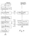
Die Erfindung samt ihren weiteren Vorteilen ist im folgenden an Hand eines Beispiels unter Bezugnahme auf die Zeichnung näher erläutert. In dieser zeigen Fig. 1 in schematischer Darstellung eine Vorrichtung zur Durchführung des Verfahrens nach der Erfindung, Fig. 2 an Hand eines zeitlichen Ablaufdiagramms ein Verfahren nach dem Stand der Technik, Fig. 3 in einem ähnlichen, ausführlicheren Diagramm das Verfahren nach der Erfindung und Fig. 4 ein vereinfachtes Flußdiagramm zum Verfahren nach der Erfindung.The invention and its further advantages are explained in more detail below using an example with reference to the drawing. 1 shows a schematic representation of an apparatus for carrying out the method according to the invention, FIG. 2 shows a method according to the prior art on the basis of a time flow diagram, FIG. 3 shows the method according to the invention in a similar, more detailed diagram Fig. 4 is a simplified flow diagram for the method according to the invention.
Gemäß Fig. 1 werden einer elektronischen Rechenschaltung 1 verschiedene Betriebsgrößen eines Motors 2, im vorliegenden Fall eines Dieselmotors, bzw. des zugehörigen Fahrzeuges zugeführt. Es handelt sich dabei in erster Linie um Signale eines Drehzahlgebers 3 und eines Gaspedalstellungssensors 4, weiters z.B. eines Motortemperatursensors 5, eines Ladedrucksensors 6 usw. Ein elektromechanisches Stellglied 7, beispielsweise ein auf das Mengenstellglied einer Verteilereinspritzpumpe 8 wirkender Stellmagnet, ist mechanisch mit einem Rückmelder 9 verbunden, dessen für die Stellung des Stellgliedes 7 repräsentatives Ausgangssignal r an die Rechenschaltung 1 zurückgeführt wird. Das Stellglied 7 wird über eine Treiberstufe 10 von dem Ausgangssignal s der Rechenschaltung 1 angesteuert. In bekannter Weise kann ein hier nicht gezeigter, nur strichliert angedeuteter Servokreis für die Stellgliedansteuerung vorgesehen sein (vgl. DE-Patentanmeldung P 37 40 443).1, various operating variables of an
In der Rechenschaltung 1 wird das Signal des Drehzahlgebers 3 in einem Drehzahlmeßblock 11 zu einem Drehzahlsignal nj verarbeitet, das bevorzugt über je einen Verbrennungshub gemessen wird. In einer darauffolgenden Mittelungsstufe 12 erfolgt eine integrale Messung z.B. über einen Verbrennungszyklus, wobei bekannte rekursive oder transversale Verfahren Verwendung finden. Hiezu verwendbare Filteralgorithmen gehören dem Stand der Technik an (z.B. "Halbleiterschaltungstechnik", U. Tietze, Ch. Schenk, Springer Verlag, 6. Auflage 1983 oder "Digitale Regelsysteme", R. Isermann, Springer Verlag 1977). Die Messung muß nicht über einen vollständigen Verbrennungszyklus erfolgen, sondern soll über die Dauer eines Verbrennungszyklus durchgeführt werden, d.h. sie kann beispielsweise über die zweite Hälfte des Verbrennungszyklus eines ersten Zylinders und über die zweite Hälfte des Verbrennungszyklus (Hubes) eines zweiten Zylinders erfolgen. Der Meßblock 11 kann in bekannter Weise Impulsformer, Frequenzteiler oder -vervielfacher enthalten, wobei auf die Art des Drehzahlgebers 3 und die Anzahl der pro Motorumdrehung anfallenden Impulse Rücksicht zu nehmen ist. Ebenso kann bei Ausfall des Drehzahlgebers 3 dem Meßblock 11 das Signal eines weiteren Drehzahlgebers, z.B. der Lichtmaschine des Fahrzeuges, zugeführt werden, wobei in diesem Zusammenhang auf die DE-A 35 01 435 verwiesen wird.In the
Das gemittelte Drehzahlsignal
Bevor auf den genaueren Funktionsablauf eingegangen wird, soll an Hand der Fig. 2 die Ermittlung des Regelsignales nach dem Stand der Technik erläutert werden. Zu einem bestimmten Zeitpunkt wird, mit dem Pfeil Mj angedeutet, ein Meßinterrupt durchgeführt, der gemessene Drehzahlwert wird eingelesen ("IN"), daraufhin werden der P-, der I- und der D-Anteil errechnet, summiert und zur Ansteuerung des Stellgliedes ausgegeben (Pfeil St). Die gesamte Zeit zwischen Eingabe des Meßwertes und Ausgabe des errechneten Wertes wird mit tTOT bezeichnet, sie bestimmt tatsächlich die Totzeit der Regelstrecke und bestimmt die Zeit tMESS zwischen aufeinanderfolgenden Messungen, wobei sinnvollerweise tMESS > tTOT gelten sollte. Wird die Meßzeit kleiner als die Totzeit, so sind einzelne Messungen sinnlos und die Rechenschaltung greift oft auf "veraltete" Meßwerte zurück.Before the more precise functional sequence is discussed, the determination of the control signal according to the prior art will be explained with reference to FIG. 2. At a certain point in time, indicated by the arrow Mj, a measurement interrupt is carried out, the measured speed value is read in ("IN"), then the P, I and D components are calculated, summed up and output to control the actuator (Arrow St). The total time between the input of the measured value and the output of the calculated value is denoted by t TOT , it actually determines the dead time of the controlled system and determines the time t MEAS between successive measurements, meaning that t MEAS > t DEAD should apply. If the measuring time is shorter than the dead time, individual measurements are pointless and the arithmetic circuit often uses "outdated" measured values.
Wie bereits eingangs erwähnt, sieht die Erfindung ein Verfahren vor, bei dem die Ermittlung des D-Anteils mit höherer Priorität, getrennt von der Ermittlung der P- und I-Anteile erfolgt. Zur Erläuterung dieses Verfahrens wird nachstehend nicht nur auf Fig. 1 sondern auch auf Fig. 3 und 4 Bezug genommen.As already mentioned at the beginning, the invention provides a method in which the determination of the D component with higher priority is carried out separately from the determination of the P and I components. To explain this method, reference is made not only to FIG. 1 but also to FIGS. 3 and 4 below.
Zu einem bestimmten Zeitpunkt wird ein Meßinterrupt durchgeführt (Pfeil Mj+1 in Fig. 3a) Der Meßwert
In Fig. 3b ist schematisch mit den Kästchen Pi, Ii die Berechnung der P- und I-Anteile angedeutet. Diese Berechnung erfolgt ohne zeitliche Kopplung an die D-Anteilsberechnung entweder kann, wenn Rechenkapazität frei ist, oder in bestimmten, vorgegebenen Zeitintervallen, z.B. alle 20 ms. Hiezu werden die Drehzahlwerte
Man erkennt aus Fig. 3 deutlich, daß die Berechnung des D-Anteils an die Meßintervalle tMESS gebunden ist, was erst durch die davon getrennte, zeitaufwendige Berechnung der P- und I-Anteile möglich ist. Die Meßzeit tMESS ist innerhalb zumindest von Drehzahlbereichen der Motordrehzahl verkehrt proportional. Dies bedeutet, daß man z.B. ab einer gewissen Drehzahl nur jeden zweiten Impuls und bei noch höheren Drehzahlen bloß jeden dritten oder vierten Impuls des Drehzahlgebers zur Berechnung verwenden kann etc. In Fig. 3 beziehen sich die Indices j auf aufeinanderfolgende Meßintervalle, wogegen die Indices i auf die wiederkehrenden P- und I-Anteilsberechnungen bezug nehmen. Das Schema nach Fig. 3 sieht die getrennte Abspeicherung der errechneten P- und I-Anteile vor. Es ist jedoch ebensogut möglich, die Summe P + I abzuspeichern und sodann zu dem D-Anteil hinzu zu addieren.It is seen from Fig. 3 shows that the calculation of the D component to the measurement intervals t MESS is attached, which is made possible by the separate therefrom, time-consuming calculation of the P and I components. The measuring time t MESS is inversely proportional to the engine speed within at least speed ranges. This means that, for example, from a certain speed, only every second pulse and at even higher speeds only every third or fourth pulse of the speed sensor can be used for the calculation, etc. In FIG. 3, the indices j relate to successive measuring intervals, whereas the indices i refer to the recurring P and I share calculations. 3 provides for the separate storage of the calculated P and I components. However, it is equally possible to store the sum P + I and then add it to the D component.
Nach der Erfindung werden somit stets "aktuelle" Drehzahlwerte
Fig. 4 veranschaulicht in übersichtlicher Weise den Ablauf des oben beschriebenen Verfahrens zur Ermittlung des Stellgliedsignales, wobei sich eine zusätzliche Erläuterung erübrigt.4 clearly illustrates the sequence of the above-described method for determining the actuator signal, an additional explanation being unnecessary.
Claims (5)
Priority Applications (1)
| Application Number | Priority Date | Filing Date | Title |
|---|---|---|---|
| AT89890078T ATE67278T1 (en) | 1988-03-16 | 1989-03-16 | METHOD FOR CONTROLLING AND REGULATING AN ENGINE OF A VEHICLE. |
Applications Claiming Priority (2)
| Application Number | Priority Date | Filing Date | Title |
|---|---|---|---|
| DE3808819A DE3808819A1 (en) | 1988-03-16 | 1988-03-16 | METHOD FOR CONTROLLING AND CONTROLLING AN INTERNAL COMBUSTION ENGINE OF A VEHICLE |
| DE3808819 | 1988-03-16 |
Publications (3)
| Publication Number | Publication Date |
|---|---|
| EP0333701A2 true EP0333701A2 (en) | 1989-09-20 |
| EP0333701A3 EP0333701A3 (en) | 1990-04-11 |
| EP0333701B1 EP0333701B1 (en) | 1991-09-11 |
Family
ID=6349893
Family Applications (1)
| Application Number | Title | Priority Date | Filing Date |
|---|---|---|---|
| EP89890078A Expired - Lifetime EP0333701B1 (en) | 1988-03-16 | 1989-03-16 | Method for controlling and regulating an automotive engine |
Country Status (4)
| Country | Link |
|---|---|
| EP (1) | EP0333701B1 (en) |
| AT (1) | ATE67278T1 (en) |
| DE (2) | DE3808819A1 (en) |
| ES (1) | ES2025856T3 (en) |
Families Citing this family (1)
| Publication number | Priority date | Publication date | Assignee | Title |
|---|---|---|---|---|
| DE102020201845A1 (en) | 2020-02-14 | 2021-08-19 | Volkswagen Aktiengesellschaft | Method for controlling an internal combustion engine when the engine is started |
Citations (3)
| Publication number | Priority date | Publication date | Assignee | Title |
|---|---|---|---|---|
| US4163282A (en) * | 1976-09-24 | 1979-07-31 | Nippondenso Co., Ltd. | Electrical control method and apparatus for combustion engines |
| DE3329800A1 (en) * | 1983-08-18 | 1985-02-28 | Robert Bosch Gmbh, 7000 Stuttgart | SPEED CONTROL SYSTEM FOR AN INTERNAL COMBUSTION ENGINE |
| WO1987002418A1 (en) * | 1985-10-09 | 1987-04-23 | Robert Bosch Gmbh | Input system for injection nozzles |
Family Cites Families (3)
| Publication number | Priority date | Publication date | Assignee | Title |
|---|---|---|---|---|
| DE2735596C2 (en) * | 1977-08-06 | 1986-09-18 | Robert Bosch Gmbh, 7000 Stuttgart | Device for electronic injection quantity control in internal combustion engines with compression ignition |
| DE2906782A1 (en) * | 1979-02-22 | 1980-09-04 | Bosch Gmbh Robert | DEVICE FOR DAMPING VIBRATION VIBRATIONS IN AN INTERNAL COMBUSTION ENGINE |
| DE3501435A1 (en) * | 1985-01-17 | 1986-07-17 | Voest-Alpine Friedmann GmbH, Linz | ARRANGEMENT FOR CONTROLLING AND REGULATING AN INTERNAL COMBUSTION ENGINE |
-
1988
- 1988-03-16 DE DE3808819A patent/DE3808819A1/en active Granted
-
1989
- 1989-03-16 EP EP89890078A patent/EP0333701B1/en not_active Expired - Lifetime
- 1989-03-16 ES ES198989890078T patent/ES2025856T3/en not_active Expired - Lifetime
- 1989-03-16 AT AT89890078T patent/ATE67278T1/en not_active IP Right Cessation
- 1989-03-16 DE DE8989890078T patent/DE58900269D1/en not_active Expired - Fee Related
Patent Citations (3)
| Publication number | Priority date | Publication date | Assignee | Title |
|---|---|---|---|---|
| US4163282A (en) * | 1976-09-24 | 1979-07-31 | Nippondenso Co., Ltd. | Electrical control method and apparatus for combustion engines |
| DE3329800A1 (en) * | 1983-08-18 | 1985-02-28 | Robert Bosch Gmbh, 7000 Stuttgart | SPEED CONTROL SYSTEM FOR AN INTERNAL COMBUSTION ENGINE |
| WO1987002418A1 (en) * | 1985-10-09 | 1987-04-23 | Robert Bosch Gmbh | Input system for injection nozzles |
Also Published As
| Publication number | Publication date |
|---|---|
| DE3808819C2 (en) | 1990-06-07 |
| DE58900269D1 (en) | 1991-10-17 |
| ES2025856T3 (en) | 1992-04-01 |
| ATE67278T1 (en) | 1991-09-15 |
| EP0333701A3 (en) | 1990-04-11 |
| DE3808819A1 (en) | 1989-09-28 |
| EP0333701B1 (en) | 1991-09-11 |
Similar Documents
| Publication | Publication Date | Title |
|---|---|---|
| EP0416270B1 (en) | Method and apparatus to control and regulate an engine with self-ignition | |
| DE2749369C2 (en) | Control system for an actuator in the additional air supply bypass duct of a throttle valve in internal combustion engines | |
| DE3015832A1 (en) | METHOD AND DEVICE FOR CONTROLLING AND / OR REGULATING THE AIR QUANTITY IN COMBUSTION ENGINES | |
| EP1254310B1 (en) | System for regulating an internal combustion engine | |
| DE102012100622A1 (en) | Fuel injection control | |
| DE102008002482A1 (en) | Method and device for calibrating a Kraftstoffzumesssystems an internal combustion engine, in particular a motor vehicle | |
| DE19749815A1 (en) | Device and method for determining the amount of fuel injected | |
| EP0449851B1 (en) | Processes for metering fuel | |
| DE3226026A1 (en) | METHOD AND DEVICE FOR THE ELECTRONIC CONTROL OF AN INTERNAL COMBUSTION ENGINE | |
| DE3046863A1 (en) | ELECTRONICALLY CONTROLLED FUEL MEASURING SYSTEM FOR AN INTERNAL COMBUSTION ENGINE | |
| EP0385969B1 (en) | Apparatus for the control and regulation of a diesel engine | |
| DE3421640A1 (en) | DEVICE FOR DETECTING THE CHANGE VALUE IN THE SPEED OF AN INTERNAL COMBUSTION ENGINE | |
| DE3423110C2 (en) | ||
| EP0502849A1 (en) | Electronic fuel-supply control system for an internal-combustion engine. | |
| EP1117930B1 (en) | Method for electronically trimming an injector | |
| EP0333701B1 (en) | Method for controlling and regulating an automotive engine | |
| EP2019195B1 (en) | Method for determining the amount of fuel injected | |
| EP0407406B1 (en) | Learning control process and device for internal combustion engines | |
| DE3009627A1 (en) | DEVICE FOR DETERMINING CONTROL AND CONTROL SIZES OF AN INTERNAL COMBUSTION ENGINE | |
| DE102008005154A1 (en) | Method and device for monitoring a motor control unit | |
| EP0353216B1 (en) | Device for controlling and regulating the combustion engine of a vehicle | |
| EP0333702B1 (en) | Method for controlling and regulating an automotive engine | |
| DE102008041485A1 (en) | Fuel injection amount learning device | |
| DE102017218112B4 (en) | Control device for injector | |
| DE3518014C2 (en) | Method for setting a throttle valve of an internal combustion engine at idle |
Legal Events
| Date | Code | Title | Description |
|---|---|---|---|
| PUAI | Public reference made under article 153(3) epc to a published international application that has entered the european phase |
Free format text: ORIGINAL CODE: 0009012 |
|
| AK | Designated contracting states |
Kind code of ref document: A2 Designated state(s): AT CH DE ES FR GB IT LI SE |
|
| PUAL | Search report despatched |
Free format text: ORIGINAL CODE: 0009013 |
|
| AK | Designated contracting states |
Kind code of ref document: A3 Designated state(s): AT CH DE ES FR GB IT LI SE |
|
| 17P | Request for examination filed |
Effective date: 19901004 |
|
| 17Q | First examination report despatched |
Effective date: 19910225 |
|
| RAP1 | Party data changed (applicant data changed or rights of an application transferred) |
Owner name: AUTOMOTIVE DIESEL GESELLSCHAFT M.B.H. |
|
| GRAA | (expected) grant |
Free format text: ORIGINAL CODE: 0009210 |
|
| AK | Designated contracting states |
Kind code of ref document: B1 Designated state(s): AT CH DE ES FR GB IT LI SE |
|
| REF | Corresponds to: |
Ref document number: 67278 Country of ref document: AT Date of ref document: 19910915 Kind code of ref document: T |
|
| REF | Corresponds to: |
Ref document number: 58900269 Country of ref document: DE Date of ref document: 19911017 |
|
| GBT | Gb: translation of ep patent filed (gb section 77(6)(a)/1977) | ||
| ITF | It: translation for a ep patent filed |
Owner name: ORGANIZZAZIONE D'AGOSTINI |
|
| ET | Fr: translation filed | ||
| REG | Reference to a national code |
Ref country code: ES Ref legal event code: FG2A Ref document number: 2025856 Country of ref document: ES Kind code of ref document: T3 |
|
| PLBE | No opposition filed within time limit |
Free format text: ORIGINAL CODE: 0009261 |
|
| STAA | Information on the status of an ep patent application or granted ep patent |
Free format text: STATUS: NO OPPOSITION FILED WITHIN TIME LIMIT |
|
| 26N | No opposition filed | ||
| EAL | Se: european patent in force in sweden |
Ref document number: 89890078.2 |
|
| PGFP | Annual fee paid to national office [announced via postgrant information from national office to epo] |
Ref country code: GB Payment date: 19970213 Year of fee payment: 9 |
|
| PGFP | Annual fee paid to national office [announced via postgrant information from national office to epo] |
Ref country code: FR Payment date: 19970214 Year of fee payment: 9 |
|
| PGFP | Annual fee paid to national office [announced via postgrant information from national office to epo] |
Ref country code: DE Payment date: 19970220 Year of fee payment: 9 Ref country code: AT Payment date: 19970220 Year of fee payment: 9 |
|
| PGFP | Annual fee paid to national office [announced via postgrant information from national office to epo] |
Ref country code: SE Payment date: 19970221 Year of fee payment: 9 |
|
| PGFP | Annual fee paid to national office [announced via postgrant information from national office to epo] |
Ref country code: CH Payment date: 19970226 Year of fee payment: 9 |
|
| PGFP | Annual fee paid to national office [announced via postgrant information from national office to epo] |
Ref country code: ES Payment date: 19970321 Year of fee payment: 9 |
|
| PG25 | Lapsed in a contracting state [announced via postgrant information from national office to epo] |
Ref country code: GB Free format text: LAPSE BECAUSE OF NON-PAYMENT OF DUE FEES Effective date: 19980316 Ref country code: AT Free format text: LAPSE BECAUSE OF NON-PAYMENT OF DUE FEES Effective date: 19980316 |
|
| PG25 | Lapsed in a contracting state [announced via postgrant information from national office to epo] |
Ref country code: SE Free format text: LAPSE BECAUSE OF NON-PAYMENT OF DUE FEES Effective date: 19980317 Ref country code: ES Free format text: LAPSE BECAUSE OF EXPIRATION OF PROTECTION Effective date: 19980317 |
|
| PG25 | Lapsed in a contracting state [announced via postgrant information from national office to epo] |
Ref country code: LI Free format text: LAPSE BECAUSE OF NON-PAYMENT OF DUE FEES Effective date: 19980331 Ref country code: FR Free format text: THE PATENT HAS BEEN ANNULLED BY A DECISION OF A NATIONAL AUTHORITY Effective date: 19980331 Ref country code: CH Free format text: LAPSE BECAUSE OF NON-PAYMENT OF DUE FEES Effective date: 19980331 |
|
| GBPC | Gb: european patent ceased through non-payment of renewal fee |
Effective date: 19980316 |
|
| REG | Reference to a national code |
Ref country code: CH Ref legal event code: PL |
|
| PG25 | Lapsed in a contracting state [announced via postgrant information from national office to epo] |
Ref country code: DE Free format text: LAPSE BECAUSE OF NON-PAYMENT OF DUE FEES Effective date: 19981201 |
|
| EUG | Se: european patent has lapsed |
Ref document number: 89890078.2 |
|
| REG | Reference to a national code |
Ref country code: FR Ref legal event code: ST |
|
| REG | Reference to a national code |
Ref country code: ES Ref legal event code: FD2A Effective date: 20000601 |
|
| PG25 | Lapsed in a contracting state [announced via postgrant information from national office to epo] |
Ref country code: IT Free format text: LAPSE BECAUSE OF NON-PAYMENT OF DUE FEES;WARNING: LAPSES OF ITALIAN PATENTS WITH EFFECTIVE DATE BEFORE 2007 MAY HAVE OCCURRED AT ANY TIME BEFORE 2007. THE CORRECT EFFECTIVE DATE MAY BE DIFFERENT FROM THE ONE RECORDED. Effective date: 20050316 |