EP0333670A2 - Druckbalkenvorrichtung für eine Papierstapel-Schneidmaschine - Google Patents
Druckbalkenvorrichtung für eine Papierstapel-Schneidmaschine Download PDFInfo
- Publication number
- EP0333670A2 EP0333670A2 EP89830110A EP89830110A EP0333670A2 EP 0333670 A2 EP0333670 A2 EP 0333670A2 EP 89830110 A EP89830110 A EP 89830110A EP 89830110 A EP89830110 A EP 89830110A EP 0333670 A2 EP0333670 A2 EP 0333670A2
- Authority
- EP
- European Patent Office
- Prior art keywords
- pressing device
- pressing
- cutter
- cutters
- ream
- Prior art date
- Legal status (The legal status is an assumption and is not a legal conclusion. Google has not performed a legal analysis and makes no representation as to the accuracy of the status listed.)
- Withdrawn
Links
Images

Classifications
-
- B—PERFORMING OPERATIONS; TRANSPORTING
- B26—HAND CUTTING TOOLS; CUTTING; SEVERING
- B26D—CUTTING; DETAILS COMMON TO MACHINES FOR PERFORATING, PUNCHING, CUTTING-OUT, STAMPING-OUT OR SEVERING
- B26D7/00—Details of apparatus for cutting, cutting-out, stamping-out, punching, perforating, or severing by means other than cutting
- B26D7/01—Means for holding or positioning work
- B26D7/02—Means for holding or positioning work with clamping means
- B26D7/04—Means for holding or positioning work with clamping means providing adjustable clamping pressure
-
- B—PERFORMING OPERATIONS; TRANSPORTING
- B26—HAND CUTTING TOOLS; CUTTING; SEVERING
- B26D—CUTTING; DETAILS COMMON TO MACHINES FOR PERFORATING, PUNCHING, CUTTING-OUT, STAMPING-OUT OR SEVERING
- B26D7/00—Details of apparatus for cutting, cutting-out, stamping-out, punching, perforating, or severing by means other than cutting
- B26D7/01—Means for holding or positioning work
- B26D7/02—Means for holding or positioning work with clamping means
- B26D7/025—Means for holding or positioning work with clamping means acting upon planar surfaces
Definitions
- the present invention relates to an improved mechanism or device to be applied to cutters in general and, in particular, to paper ream cutters.
- ream cutters are frequently used for cutting paper stacks including several paper sheets, and a drawback of these known cutters is that they comprise rather complex devices for adjusting the manual cutting force depending on the pressure which is necessary for firmly retaining the sheets to be cut.
- the aim of the present invention is to overcome the above mentioned drawbacks, by providing an improved pressing device which can be quickly and easily adjusted depending on the ream thickness.
- a main object of the present invention is to provide such a pressing device which is very simple construction-wise.
- Another object of the present invention is to provide such a pressing device which can be fitted to different cut spans, both in the width and in the length direction.
- an improved pressing device for cutters in general and, in particular, for ream cutters, characterized in that said pressing device comprises a lever system for adjusting the operating height of said device and resilient means for continuously adjusting the locking pressure on the paper sheet ream to be cut.
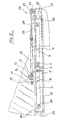
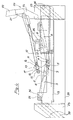
- the improved pressing mechanism or device comprises a lever system, including an articulation member 1, pivoted on the cross member 2 of the cutter frame, and two like length levers 3 and 4, coupled to one another, the first 3 of which is pivoted by a pawl 9 in a slot 5 formed through the articulation member 1.
- the first and second levers 3 and 4 are coupled through a pin 6 and a slot 7 respectively associated with said levers according to a possible embodiment; alternatively, the pin 6 and slot 7 can be respectively formed on the lever 4 and lever 3.
- said levers 3 and 4 are pivoted on central pins 8, which are affixed to the cross member of the cutter frame 2, and have a length which depends on the size of the articulation member 1, so as to cause the pressing member proper 18 to be lowered before the lowering of the cutting blade 25 or 30.
- the lever system further comprises pressure adjusting resilient means consisting of a coil spring 11, coiled on a supporting rod member 12 and provided, at one end thereof, with a stop member.
- the adjusting and size of the coil spring 12 will depend on the size of the levers 3 and 4 and articulation member 1, and will be so selected as to hold the pressing member 18 properly pressed on the ream to be cut.
- a perforated coupling 13 which is applied on a pin 14 affixed near the top end portion of the articulation member 1.
- a spacer member 17 so as to allow for the nut 15 to adjust, as the pressing member 18 is arranged in a completely raised condition, the spacing to the working surface 39 of the abutment 19 formed at the bottom portion of said pressing member 18.
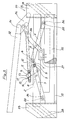
- a pushing lever 26 In a ream cutter 20, between the bottom portion 21 of the operating arm 22, which is pivoted to the guiding uprights 23 of the pressing member 18, through a driving articulated coupling 24 therewith said pressing member is rigid, and the cutting blade 25, there is arranged a pushing lever 26.
- This pushing lever 26 has an angled contour and is pivoted at one end thereof on an adjusting block 27 which is applied on the top of a blade holder 34 and, at the other end portion thereof, in said driving articulated coupling 24.
- a cutter 28 instead of the pushing lever 26, there is provided a suitable interspacing between the pivot point 29 of the cutting blade 30, affixed on the attachement block 31 of said cutting blade 30 to the cutter frame, and the pivot pin 32 of the coupling 33 at the end of the rod member 12 (supporting the coil spring 11) affixed to the cutting blade holder 34.
- the pressing member is provided, at the end portions thereof, with two pins 35 adapted to slide in slots 36 each formed at the free end portion of the two levers 3 and 4, so as to cause the abutment 19 to be precisely lowered with an accurate parallel relationship to the operating surface 39.
- the pressing member can be provided with the slots 36 and the levers 3 and 4 with the pins 35.
- the end stop member for the coil spring can consist of a small block 37, either of the fixed or of the adjustable type, said small block being slidingly engaged on the rod member 12.
- lever system according to the present invention affords the possibility of adjustably lowering the pressing member 18 before the lowering of the rectilinear cutting blade of the cutter 20 or the curved cutting blade 30 of the cutter 28, whilst the disclosed resilient means are effective to continuously adjust the ream holding pressure.
- the lowering movement of the cutting blade 25 is controlled by two pairs of guides 38, associated with the guiding uprights 23 of the pressing member 18, whereas the lowering movement of the cutting blade 30 is controlled by the relating movement of the pivot pin 29 and pivot pin 32.
Landscapes
- Life Sciences & Earth Sciences (AREA)
- Forests & Forestry (AREA)
- Engineering & Computer Science (AREA)
- Mechanical Engineering (AREA)
- Nonmetal Cutting Devices (AREA)
- Details Of Cutting Devices (AREA)
Applications Claiming Priority (2)
| Application Number | Priority Date | Filing Date | Title |
|---|---|---|---|
| IT8819753A IT1224622B (it) | 1988-03-11 | 1988-03-11 | Meccanismo di pressione perfezionato per taglierine e tagliarisme in genere. |
| IT1975388 | 1988-03-11 |
Publications (2)
| Publication Number | Publication Date |
|---|---|
| EP0333670A2 true EP0333670A2 (de) | 1989-09-20 |
| EP0333670A3 EP0333670A3 (de) | 1991-06-12 |
Family
ID=11160952
Family Applications (1)
| Application Number | Title | Priority Date | Filing Date |
|---|---|---|---|
| EP19890830110 Withdrawn EP0333670A3 (de) | 1988-03-11 | 1989-03-10 | Druckbalkenvorrichtung für eine Papierstapel-Schneidmaschine |
Country Status (2)
| Country | Link |
|---|---|
| EP (1) | EP0333670A3 (de) |
| IT (1) | IT1224622B (de) |
Cited By (1)
| Publication number | Priority date | Publication date | Assignee | Title |
|---|---|---|---|---|
| CN112276321A (zh) * | 2020-11-18 | 2021-01-29 | 江苏玄博智能标识科技有限公司 | 一种信息指示牌加工用裁切装置 |
Family Cites Families (6)
| Publication number | Priority date | Publication date | Assignee | Title |
|---|---|---|---|---|
| BE385994A (de) * | ||||
| GB191309601A (en) * | 1912-05-02 | 1914-02-12 | Bautzner Ind Mit Beschraenkter | Improvements in Machines for Cutting Piles of Paper and the like. |
| US2089274A (en) * | 1935-07-01 | 1937-08-10 | Alfa Machine Company | Cutting machine |
| CH366817A (de) * | 1958-06-27 | 1963-01-31 | Polygraficke Z N P Bratislava | Bogenschneidemaschine mit einer automatischen Abführeinrichtung |
| DE2727817C3 (de) * | 1977-06-21 | 1980-02-07 | Wilhelm Dahle Buero- Und Zeichengeraetefabrik, 8630 Coburg | Schneideinrichtung, insbesondere Stapelschneider |
| PL128486B1 (en) * | 1980-03-04 | 1984-01-31 | Zaklady Mechaniczne Przemyslu | Mechanical drive unit for hold-down bar in copying machine provided with facilities for cutting stacks of paper sheets |
-
1988
- 1988-03-11 IT IT8819753A patent/IT1224622B/it active
-
1989
- 1989-03-10 EP EP19890830110 patent/EP0333670A3/de not_active Withdrawn
Cited By (1)
| Publication number | Priority date | Publication date | Assignee | Title |
|---|---|---|---|---|
| CN112276321A (zh) * | 2020-11-18 | 2021-01-29 | 江苏玄博智能标识科技有限公司 | 一种信息指示牌加工用裁切装置 |
Also Published As
| Publication number | Publication date |
|---|---|
| EP0333670A3 (de) | 1991-06-12 |
| IT8819753A0 (it) | 1988-03-11 |
| IT1224622B (it) | 1990-10-04 |
Similar Documents
| Publication | Publication Date | Title |
|---|---|---|
| US5740712A (en) | Punching devices | |
| DE602004001233T2 (de) | Blattklemmmechanismus | |
| DE69218498T2 (de) | Automatische Blattzuführvorrichtung mit Schrägstellungskorrektur | |
| DE69029434T2 (de) | Verfahren und Vorrichtung zum Aufbringen von harten oder weichen Einbanddecken auf gebundenen oder ungebundenen Dokumenten | |
| US7108257B2 (en) | Sheet-supply device | |
| US5431519A (en) | Spreading device for a binding apparatus and combined punch and binding apparatus | |
| EP0333670A2 (de) | Druckbalkenvorrichtung für eine Papierstapel-Schneidmaschine | |
| SE442238B (sv) | Maskin med fingerskyddsanordning | |
| DE2108064A1 (de) | Blechschere | |
| GB2139542A (en) | A punching unit in a punching and/or binding machine for joining together a pack of sheets by a comb binder | |
| US2638986A (en) | Portable punching machine | |
| EP2218564A1 (de) | Fliesenschneider mit verstellbarer Werkzeugaufnahme | |
| EP1674197A1 (de) | Vorschubvorrichtung für plattenförmige Werkstücke | |
| EP0017813B1 (de) | Auslöser für ein thermisches Schutzrelais | |
| EP0689497B1 (de) | Stanzvorrichtung | |
| CN222221915U (zh) | 一种铜棒剪切机的自动收料装置 | |
| JP2001519718A (ja) | 金属板の縁部に溝形曲げ部を形成するための曲げプレス機 | |
| US3522646A (en) | Method of producing clips for springs | |
| EP0186300A2 (de) | Schneidvorrichtung für blattförmiges Material | |
| US5361662A (en) | Moving hydraulic press | |
| US20070039442A1 (en) | Cutting unit for trimming sheet material | |
| US3063320A (en) | Cutter guard | |
| EP0003864A1 (de) | Verschiebbar auf einer Achse angeordnete Vorrichtung und Klemmeinrichtung dafür | |
| DE69232654T2 (de) | Werkzeugträger für eine Fliesenschneidvorrichtung | |
| US4019416A (en) | Hydraulic paper cutter |
Legal Events
| Date | Code | Title | Description |
|---|---|---|---|
| PUAI | Public reference made under article 153(3) epc to a published international application that has entered the european phase |
Free format text: ORIGINAL CODE: 0009012 |
|
| AK | Designated contracting states |
Kind code of ref document: A2 Designated state(s): AT BE CH DE ES FR GB LI NL SE |
|
| PUAL | Search report despatched |
Free format text: ORIGINAL CODE: 0009013 |
|
| AK | Designated contracting states |
Kind code of ref document: A3 Designated state(s): AT BE CH DE ES FR GB LI NL SE |
|
| 17P | Request for examination filed |
Effective date: 19911120 |
|
| 18W | Application withdrawn |
Withdrawal date: 19920513 |
|
| STAA | Information on the status of an ep patent application or granted ep patent |
Free format text: STATUS: THE APPLICATION HAS BEEN WITHDRAWN |
|
| R18W | Application withdrawn (corrected) |
Effective date: 19920513 |