EP0333308B1 - Doppellumenkatheter - Google Patents
Doppellumenkatheter Download PDFInfo
- Publication number
- EP0333308B1 EP0333308B1 EP19890300364 EP89300364A EP0333308B1 EP 0333308 B1 EP0333308 B1 EP 0333308B1 EP 19890300364 EP19890300364 EP 19890300364 EP 89300364 A EP89300364 A EP 89300364A EP 0333308 B1 EP0333308 B1 EP 0333308B1
- Authority
- EP
- European Patent Office
- Prior art keywords
- catheter
- lumen
- tubing
- dual lumen
- distal end
- Prior art date
- Legal status (The legal status is an assumption and is not a legal conclusion. Google has not performed a legal analysis and makes no representation as to the accuracy of the status listed.)
- Expired - Lifetime
Links
Images
Classifications
-
- A—HUMAN NECESSITIES
- A61—MEDICAL OR VETERINARY SCIENCE; HYGIENE
- A61M—DEVICES FOR INTRODUCING MEDIA INTO, OR ONTO, THE BODY; DEVICES FOR TRANSDUCING BODY MEDIA OR FOR TAKING MEDIA FROM THE BODY; DEVICES FOR PRODUCING OR ENDING SLEEP OR STUPOR
- A61M25/00—Catheters; Hollow probes
- A61M25/0021—Catheters; Hollow probes characterised by the form of the tubing
- A61M25/0023—Catheters; Hollow probes characterised by the form of the tubing by the form of the lumen, e.g. cross-section, variable diameter
- A61M25/0026—Multi-lumen catheters with stationary elements
- A61M25/003—Multi-lumen catheters with stationary elements characterized by features relating to least one lumen located at the distal part of the catheter, e.g. filters, plugs or valves
- A61M2025/0031—Multi-lumen catheters with stationary elements characterized by features relating to least one lumen located at the distal part of the catheter, e.g. filters, plugs or valves characterized by lumina for withdrawing or delivering, i.e. used for extracorporeal circuit treatment
-
- A—HUMAN NECESSITIES
- A61—MEDICAL OR VETERINARY SCIENCE; HYGIENE
- A61M—DEVICES FOR INTRODUCING MEDIA INTO, OR ONTO, THE BODY; DEVICES FOR TRANSDUCING BODY MEDIA OR FOR TAKING MEDIA FROM THE BODY; DEVICES FOR PRODUCING OR ENDING SLEEP OR STUPOR
- A61M25/00—Catheters; Hollow probes
- A61M25/0021—Catheters; Hollow probes characterised by the form of the tubing
- A61M25/0023—Catheters; Hollow probes characterised by the form of the tubing by the form of the lumen, e.g. cross-section, variable diameter
- A61M25/0026—Multi-lumen catheters with stationary elements
- A61M2025/0037—Multi-lumen catheters with stationary elements characterized by lumina being arranged side-by-side
-
- A—HUMAN NECESSITIES
- A61—MEDICAL OR VETERINARY SCIENCE; HYGIENE
- A61M—DEVICES FOR INTRODUCING MEDIA INTO, OR ONTO, THE BODY; DEVICES FOR TRANSDUCING BODY MEDIA OR FOR TAKING MEDIA FROM THE BODY; DEVICES FOR PRODUCING OR ENDING SLEEP OR STUPOR
- A61M25/00—Catheters; Hollow probes
- A61M25/0021—Catheters; Hollow probes characterised by the form of the tubing
- A61M25/0023—Catheters; Hollow probes characterised by the form of the tubing by the form of the lumen, e.g. cross-section, variable diameter
- A61M25/0026—Multi-lumen catheters with stationary elements
- A61M25/0029—Multi-lumen catheters with stationary elements characterized by features relating to least one lumen located at the middle part of the catheter, e.g. slots, flaps, valves, cuffs, apertures, notches, grooves or rapid exchange ports
Definitions
- This invention relates to a dual lumen catheter and more particularly to such a catheter for insertion into a vein of a patient for use in haemodialysis treatments.
- the invention also relates to methods for manufacturing the dual lumen catheter.
- Dual lumen catheters have been available for many years for a variety of medical purposes. It is only in recent years, however, that such catheters have been developed for use in haemodialysis.
- the general form of dual lumen catheters goes back to as early as 1882 when Brunswicke patented such a catheter in the United States under Serial No. 256,590.
- This patent teaches a flexible dual lumen catheter which is used primarily for cleaning and drainage of, for example, the bladdar, rectum, stomach and ear. In this type of catheterization, the catheter is introduced into an existing body orifice without the use of any puncturing needle or guidewire.
- Haemodialysis can be defined as the temporary removal of blood from a patient for the purpose of extracting or separating toxins therefrom and the return of the cleansed blood to the same patient. Haemodialysis is indicated in patients where renal impairment or failure exists, that is, in cases where the blood is not being properly or sufficiently cleansed, (particularly to remove water) by the kidneys.
- haemodialysis has to be carried out on a repetitive basis.
- end stage kidney disease where transplanation of kidneys is not possible or for medical reasons is contra-indicated, the patient will have to be dialysed about 100 to 150 times per year. This can result in several thousand accesses to the blood stream to enable the active haemodialysis to be performed over the remaining life of the patient;
- Dr. Stanley Shaldon and colleagues developed, in the Royal Free Hospital in London, England, a technique for haemodialysis by percutaneous catheterization of deep blood vessels, specifically the femoral artery and vein. The technique was described in an article published by Dr. Shaldon and his associates in the October 14th, 1961 edition of The Lancet at Pages 857 to 859. Dr. Shaldon and his associates developed single lumen catheters having tapered tips for entry over a Seldinger wire to be used in haemodialysis. Subsequently, Dr. Shaldon and his colleagues began to insert single lumen inlet and outlet catheters in the femoral vein and this was reported in the British Medical Journal of June 19th, 1963.
- Dr. Shaldon used the femoral vein and in about 1977 Dr. P.R. Uldall, in Toronto Western Hospital, Canada, began clinical testing of a subclavian catheter that would remain in place between dialysis treatments. An article describing this was published by Dr. Uldall and others in Dialysis and Transplantation, Volume 8, No. 10, in October 1979. Subsequently Dr. Uldall began experimenting with a coaxial dual lumen catheter for subclavian insertion and this resulted in Canadian Patent No. 1,092,927 which issued on January 6, 1981. Although this particular form of catheter has not achieved significant success in the market-place, it was the forerunner of dual lumen catheters implanted in the subclavian vein for periodic haemodialysis.
- U.S. Patent No. 4,451,252 also to Martin.
- This utilizes the well known dual lumen configuration in which the lumens are arranged side-by-side separated by a diametric septum.
- the structure shown in this patent provides for a tip making it possible to enter a Seldinger wire through one of the lumens and to use this wire as a guide for inserting the catheter percutaneously.
- This type of structure is shown in a European Patent Application to Edelman published under No. 0 079 719, and in U.S. Patent Nos. 4,619,643, representing the closest prior art, 4,583,968, 4,568,329, 4,543,087, 4,692,141, 4,568,329, and U.S. Design Patent No. 272,651.
- the tip of the catheter must possess sufficient rigidity so that it does not concertina as it contacts the skin because this would enlarge the skin puncture as the catheter is being entered over the wire. To some extent this is at odds with the desirable materials qualities of the main body of catheter which should be soft and flexible for patient comfort.
- manufacturers have formed a variety of tips within the limitations of using a single extrusion from which the body and tip are formed. The result is that the tips have in general been made by using some of the excess material found in the shorter intake lumen.
- U.S. Patent No. 4,551,292 discloses a catheter with a soft and deformable tip of a different material in order to decrease likelihood of injury to body tissue upon insertion and removal of the catheter.
- the degree of rigidity in the tip becomes more important if the catheter is to reside in the patient for prolonged periods, as is becoming more common in many treatments, notably haemodialysis. This is because although ideally the catheter lies in the middle of the vein, in practice it will bear against the vessel wall. In such circumstances it is possible that a stiff tip could damage or even embed itself in the vessel wall when left in place for extended periods.
- the body of the catheter should be flexible to take up curved positions with a minimum of stress.
- the tip should take up position in the vein without placing a load on the vein wall, and thirdly the catheter must be sufficiently robust to withstand the forces applied during insertion using the Seldinger technique.
- the external surface of the catheter should be smooth and any changes in cross-sectional area along the length of the catheter should take place gradually and without sudden changes in section. It is among the objects of this invention to provide catheters which meet some or all of these desirable characteristics and to provide methods of making such catheters.
- a flexible dual lumen catheter having a first portion and a second portion and comprising an intake lumen having a closed distal end and a side opening immediately adjacent the distal end to receive fluid for extraction, and a return lumen, the second portion extending longitudinally beyond the distal end of the intake lumen, said second portion terminating at an opening to return said fluid, characterised in that said second portion is of a material having a greater flexibility than that of the remainder of the catheter.
- a flexible catheter of the invention may be made from an elongate tubular first portion of thermoplastic material of larger diameter and having an outer wall and a septum dividing the tube into first and second D-shaped passageways, and a tubular second portion of thermoplastic material and of smaller diameter, by the steps of: deforming the second portion to engage over an end of the first portion and maintaining this arrangement; engaging a first mandrel in the first passageway ending adjacent the end of this passageway, and engaging a second mandrel in the second passageway and in the second portion applying sufficient heat locally to cause the material of said portions to close off the end of the first passageway to form a first lumen, to cause a smooth internal transition from the second passageway to the tubular second portion to form a second lumen, and to cause a smooth external transition from the first to the second portions.
- a flexible catheter of the invention may alternatively be made by the steps of: providing a first portion having a first cross-sectional area, a distal end, a proximal end, an outer wall and a continuous septum extending internally between spaced points on the outer wall to define D-shaped first and second passageways; providing a second tubular portion having a second cross-sectional area smaller than said first cross-sectional area, a distal end, a proximal end, and an outer wall; forming the distal end of the second portion such that the cross-sectional area reduces gradually to form a tip having an end opening; forming the proximal end of the second portion such that the cross-sectional area increases gradually to form a flare having an internal cross-sectional area larger than said first cross-sectional area; smoothly merging the distal end of the first portion and the proximal end of the second portion together at a transition portion, while merging the outer wall of the first passageway and the septum to close the first passageway at the transition portion to form
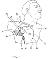
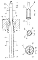
- Fig. 1 of the drawings illustrates a dual lumen catheter indicated generally by reference numeral 20 according to a preferred embodiment of the present invention, and a patient shown, by way of example, receiving the catheter in the subclavin vein using a Seldinger wire 22.
- the catheter 20 is to be used for haemodialysis treatment and could of course be entered in a similar manner in the femoral vein.
- the catheter 20 is secured to a conventional dressing 24 by an attachment fitting 26 having wing tabs 28, and the dressing 24, in turn, is secured to the skin of the patient.
- the catheter passes through the dressing 24 and, as can be seen in broken outline, a flexible elongate and substantiallly cylindrical body 30, formed of polyurethane extrusions (as will be described below) is inserted through the skin and into the subclavin vein in the downstream direction.
- the catheter 20 has at its distal end 32 a tip 34, described in greater detail below.
- a tip 34 is at the other end of the body 30, which protrudes outwardly and is secured by dressing 24.
- Cylindrical blood extraction and return tubes 38, 40 are attached to the connector 36, a more detailed description of which is also provided below. For the moment it is sufficient to state that these tubes 38, 40 are connected to lumens running through the body 30.
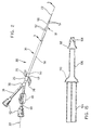
- Fig. 2 shows the catheter 20 in greater detail.
- the body 30 terminates at its proximal end in the connector 36, for receiving the blood extraction and return tubes 38, 40. These tubes terminate at their outer ends at respective female luer fittings 42 for connection to complementary male luer fittings (not shown) leading to a dialysis machine, and carry closure clamps 46 (one of which is shown) to selectively close the tubes.
- the wing tabs 28, sometimes known as suture wings, are formed integrally with a central tubular portion 48 which can rotate on the body 30 and is retained in place by a shoulder on the end of the connector 36 and a second shoulder on a reinforcing portion 50 so that the catheter 20 can be rotated relative to the tabs 28. This rotation is sometimes necessary after insertion of the catheter 20 to change the position of intake side apertures in the distal end 32 if the apertures happen to be occluded by engagement of the wall of the vein. Details of the apertures are provided below.
- the reinforcing portion 50 is blended into the body 30 over the length of the portion and assists in strengthening the catheter to minimize the likelihood of kinking. Also, the portion 50 assists in sealing the puncture site where the catheter enters the patient.
- the return tube 40 is aligned with a return lumen to permit the Seldinger wire 22 to pass through the catheter.
- the wire exits at the tip 34 which is of a reduced cross section so that the catheter can slide over the wire and into the patient.
- the extraction and return tubes 38, 40 are linked at the connector 36 with lumens in the body 30 to connect with respective groups of apertures 52, 54 (some of which can be seen in this view) at the distal end of the catheter.
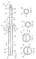
- the body 30 is made up of a main or first portion 56 and a lesser second portion 58 at the distal end of the first portion.
- the distal end 32 is made up of the distal end of the first portion 56 and the second portion 58.
- the portion 56 has an outer wall 60 and an integral septum 62 extending diametrically to define two D-shaped passageways 64, 66 (see also Fig. 4) having rounded corner portions to avoid blood stagnation.
- the passageway 64 is closed at its distal end to define an extraction lumen and the passageway 66 connects with the second portion 58 to define a return lumen.
- the first and second portions 56, 58 merge smoothly at a transition portion 68 of decreasing cross section and the second portion leads smoothly from the first portion 56.
- the tubular second portion 58 comprises an outer wall 70 which combines with passageway 66 to form a return lumen 72.
- the extraction lumen consists essentially of the passageway 64 and terminates in the transition portion 68 of decreasing cross section where the septum 62 merges with the outer wall 60.
- the distal end of the extraction lumen is formed by material at the transition portion 68 such that one of the openings 52a is at the very end of the lumen to minimize the risk of blood stagnating at the end of the lumen.
- the other apertures 52 are provided at spaced points in the outer wall 60, thus allowing the inflow of blood from the vein into the lumen.
- the return apertures 54 are located at spaced points in the outer wall 70 of the second portion 58.
- the tip 34 also includes an end aperture 74 through which the Seldinger wire 22 passes.
- the end aperture 74 is of corresponding diameter to the Seldinger wire 22.
- the tip 34 in addition to the transition portion 68 between the first and second portions 56, 58, the tip 34 includes a portion of decreasing cross section 77. Both of these portions 68, 77 faciliate insertion of the catheter 20 over the Seldinger wire 22 at the puncture site as the increase in cross section from the tip 34 to the first portion 56 is gradual and the second portion 58 acts as a dilator for the larger first portion 56. The gradual increase in cross section also reduces the likelihood of kinking at the points on the catheter where the changes in cross section occur.
- FIG. 4 is a cross-section of the first portion 56 and shows the septum 62 extending diametrically to define the two similar D-shaped passageways 64 and 66 contained by the outer wall 60.
- Fig. 5 shows the initial stages of transition from the first portion 56 to the second portion 58.
- the passageway 64 is smaller and is converging towards its end.
- Fig. 6 shows the shape of lumen 72 during transition and it will be seen that there is some flatness at the top (as drawn) of the lumen 72 caused by the transition from D-shaped to round. Finally the section becomes round as shown in Fig. 7 with an outer diameter smaller than that of the portion 56 and also smaller than the transition diameter shown in Fig. 6.
- the tip 54 of the catheter 20 When placed in a blood vessel the tip 54 of the catheter 20 will often rest against the side wall of the vessel. Where the catheter tip is of a stiff material the continued pressure of the tip against the vessel wall may be sufficient to damage the vessel wall or to embed the tip in the vessel wall.
- the first and second portions 56, 58 may be of material having different properties which are capable of assembly as will be described. For instance, the first portion 56 may be of a stiffer material than the second portion 58. It is also necessary that the catheter is not of a material that is so flexible that it will concertina is it is pushed over the Seldinger wire 22 during insertion at the puncture site.
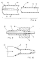
- the shapes of extruded material used to make the catheter are shown in Fig. 8.
- Two lengths of smooth polyurethane tubing 78, 80 are used, the larger diameter tubing 78 being used to form the first portion 56 (Fig. 3), and the smaller diameter tubing 80 being used to form the second portion 58.
- the size of the larger tubing will be 11 French (11F) and the smaller tubing 8 French (8F).
- the larger cross section tubing 78 is shorter than the desired total length of the catheter 20 and has an outer wall 60 of about 0.015 inches thickness and a integral septum 62 of about 0.010 inches thickness.
- the smaller cross section tubing 80 is considerably shorter and has an outer wall 70 of about 0.017 inches thickness to define a single lumen 72.
- Fig. 9 illustrates the process used for forming the tip 34 on the smaller cross section tubing 80.
- a round support wire 82 is placed inside a length of the tubing 80, which is then pushed into a heated die 84 having a shape corresponding to the desired shape of the portion 77 (Fig. 3).
- the wire 82 provides internal support during the forming operation.
- the tubing and wire are then removed from the die 84 and allowed to cool so that the tubing will harden.
- a flared portion 86 is then formed on the other end of the tubing 80 by the insertion of a heated conical mandrel 88.
- the internal diameter of at least a part of the flared portion 86 is greater than the external diameter of the larger tubing 78.
- the smaller tubing 80 may be fitted over the distal end of the larger tubing 78, as shown in Fig. 9.
- stiff support wires 94, 96 are located in the larger tubing 78, as shown in Fig. 11.
- the support wire 94 located in the passageway 64 has a D-shaped cross-section, as can be seen ing Fig. 12, and a rounded end 97 which is located at the end of the passageway 64.
- the support wire 96 in the other passageway 66 has a portion 98 with a D-shaped cross-section, as seen in Fig. 12, which fits in the passageway 66 and an end portion 100 with a circular cross-section, as seen in Fig. 13, which extends from the end of the first portion 56. If reference is made to Figs. 12 and 13, it will be noted that the cylindrical section 100 has a greater diameter than the height of the passageways in the dual lumen tubing seen in Fig. 12. It will be realized therefore that the walls and septum of the D-shaped passageway 66 must stretch to accommodate the cylindrical portion 100 on insertion and extraction of the wire 96.
- the support wires 94, 96 are then held in place and the flared portion 86 of the smaller tubing 80 pushed onto the distal end of the larger tubing, the cylindrical portion 100 of the support wire 96 being received by the tubing 80. It is important that the support wire 94, 96 do not touch to ensure that there is structural separation between the lumens after the catheter is completed.
- a silicon rubber sleeve 90 is slipped over the ends of the tubing 78, 80.
- the inner diameter of the sleeve 90 corresponds to the outer diameter of the original tubing 80 and tends to compress the ends of the tubing 78, 80 inwardly.
- this assembly is located within two halves of a heated die 92 which is shown partially opened in Fig. 9.
- the first portion 56 is supported against kinking and the aforementioned concertina effect during insertion by the Seldinger wire 22, and by the cylindrical form of the portion 56 which has considerable strength in compression.
- the flared portion 86 may be formed before the portion 77 of decreasing cross section and this portion 77 may then be formed after the two pieces of tubing 78, 80 have been merged.
- the support wire 96 is to be inserted from the distal end of the tubing 80 and similarly with the insertion of the support wire 96 described above, the tubing would have to stretch to accommodate the D-shaped portion as its passed through the tubing 80.
- tubing 78, 80 may be of different colours to indicate the respective properties or diameters of the tubing and thus may serve to provide a clear indication to a physician of the properties of a particular catheter.
- Fig. 15 illustrates a step in the manufacture of a catheter in accordance with a further embodiment of the present invention.
- the distal end of the catheter is being formed of three different pieces of tubing 104, 106, 108, the larger cross section tubing 104 corresponding to the larger cross section tubing 78, the smaller cross section tubing 108 corresponding in cross-section to the smaller piece of tubing 80 though being considerably shorter, and an intermediate piece of tubing 106 of similar cross section but of greater length than the tubing 108.
- the intermediate piece of tubing 106 is flared by a mandrel similar to that shown in Fig. 10 such that its flared portion 110 has an internal diameter greater than the external diameter of the tubing 104.
- the undeformed distal end of the tubing 106 is received by a flared portion 112 of the tubing 108.
- This embodiment illustrates that a greater number of pieces of tubing having differing properties may be used to form the distal end of a catheter having a combination of particular properties, and that a tip may be formed by different material having different properties.
- the tubing 108 would normally be of a softer or more flexible material to form a softer or more flexible tip. Also, parts can be pre-formed or moulded for subsequent use in the assembly.
- the catheters described above demonstrate embodiments of the present invention which facilitate insertion of a catheter through a skin puncture, while providing a flexible distal end portion or tip.
Claims (8)
- Flexibler Doppellumenkatheter (20) mit einem ersten Abschnitt (56) und einem zweiten Abschnitt (58) und mit einem Einlaßlumen (64), welches ein geschlossenes distales Ende und eine Seitenöffnung (52) in unmittelbarer Nähe des distalen Endes aufweist, um ein Extraktionsfluid aufzunehmen, und einem Rücklauflumen (72), wobei der zweite Abschnitt (58) sich in Längsrichtung hinter das distale Ende des Einlaßlumens erstreckt und in einer Öffnung (74) zum Rücklauf des Fluides endet,
dadurch gekennzeichnet,
daß der zweite Abschnitt aus einem Material mit einer größeren Flexibilität als der restliche Teil des Katheters besteht. - Flexibler Doppellumenkatheter nach Anspruch 1,
dadurch gekennzeichnet,
daß das Einlaßlumen (64) im Bereich des Abschnitts (58) mit einer Querschnittsverminderung in Richtung auf den Abschnitt endet. - Flexibler Doppellumenkatheter nach Anspruch 1 oder 2,
dadurch gekennzeichnet,
daß der Abschnitt (58) aus einem anderen Material als der restliche Teil des Katheters besteht. - Flexibler Doppellumenkatheter nach Anspruch 1, 2 oder 3,
dadurch gekennzeichnet,
daß ein erster Abschnitt (56) mit einem gleichmäßigen Durchmesser und ein zweiter Abschnitt (58) mit einem gleichmäßigen Durchmesser vorgesehen sind und
daß ein Übergangsabschnitt (68) vorgesehen ist, welcher einen fließenden Übergang zwischen dem ersten und dem zweiten Durchmesser bildet. - Flexibler Doppellumenkatheter nach Anspruch 4,
dadurch gekennzeichnet,
daß des Einlaßlumen (64) einen D-förmigen Querschnitt (64) aufweist und mit einem geschlossenen Ende an dem Übergangsabschnitt (68) endet, und
daß das Rücklauflumen (72) einen D-förmigen Querschnitt (66) in dem ersten Abschnitt und einen runden Querschnitt in dem zweiten, flexibleren Abschnitt aufweist. - Flexibler Doppellumenkatheter nach Anspruch 5,
dadurch gekennzeichnet,
daß die D-förmigen Querschnitte (64, 66) der zwei Lumen ähnlich sind. - Flexibler Doppellumenkatheter nach Anspruch 4, 5 oder 6,
dadurch gekennzeichnet,
daß der erste und der zweite Abschnitt (56, 58) aus Polyurethan mit unterschiedlichen physikalischen Eigenschaften gebildet sind. - Flexibler Doppellumenkatheter nach Anspruch 7,
dadurch gekennzeichnet,
daß der erste und der zweite Abschnitt (56, 58) aus Materialien mit unterschiedlichen Farben bestehen, wobei jede Farbe die Eigenschaften des Materials anzeigt.
Applications Claiming Priority (2)
| Application Number | Priority Date | Filing Date | Title |
|---|---|---|---|
| CA561705 | 1988-03-17 | ||
| CA561705 | 1988-03-17 |
Publications (3)
| Publication Number | Publication Date |
|---|---|
| EP0333308A2 EP0333308A2 (de) | 1989-09-20 |
| EP0333308A3 EP0333308A3 (de) | 1991-04-24 |
| EP0333308B1 true EP0333308B1 (de) | 1995-01-11 |
Family
ID=4137656
Family Applications (1)
| Application Number | Title | Priority Date | Filing Date |
|---|---|---|---|
| EP19890300364 Expired - Lifetime EP0333308B1 (de) | 1988-03-17 | 1989-01-16 | Doppellumenkatheter |
Country Status (4)
| Country | Link |
|---|---|
| EP (1) | EP0333308B1 (de) |
| JP (1) | JPH01303159A (de) |
| DE (1) | DE68920461T2 (de) |
| HK (1) | HK1007512A1 (de) |
Cited By (16)
| Publication number | Priority date | Publication date | Assignee | Title |
|---|---|---|---|---|
| US5100395A (en) * | 1989-10-06 | 1992-03-31 | Lior Rosenberg | Fluid drain for wounds |
| EP0535874A1 (de) * | 1991-09-26 | 1993-04-07 | Med-Pro Design, Inc. | Koaxial-Katheter |
| US5348536A (en) * | 1993-08-02 | 1994-09-20 | Quinton Instrument Company | Coextruded catheter and method of forming |
| US5403291A (en) * | 1993-08-02 | 1995-04-04 | Quinton Instrument Company | Catheter with elongated side holes |
| US5556390A (en) * | 1995-03-07 | 1996-09-17 | Quinton Instrument Company | Catheter with oval or elliptical lumens |
| US5795326A (en) * | 1997-01-29 | 1998-08-18 | Baxter International Inc. | Double lumen tubing design for catheter |
| US5830196A (en) * | 1995-09-21 | 1998-11-03 | Tyco Group S.A.R.L. | Tapered and reinforced catheter |
| US5968009A (en) * | 1997-01-29 | 1999-10-19 | Baxter International Inc. | Double lumen tubing design for catheter |
| US6595966B2 (en) | 1998-02-24 | 2003-07-22 | Scimed Life Systems, Inc. | High flow rate dialysis catheters and related methods |
| US6620202B2 (en) | 2001-10-16 | 2003-09-16 | Scimed Life Systems, Inc. | Medical stent with variable coil and related methods |
| US6656146B1 (en) | 1995-11-07 | 2003-12-02 | Scimed Life Systems, Inc. | Medical device with tail(s) |
| US6676623B2 (en) | 2001-05-04 | 2004-01-13 | Scimed Life Systems, Inc. | Drainage devices and methods |
| US6976973B1 (en) | 2000-10-12 | 2005-12-20 | Baxter International Inc. | Peritoneal dialysis catheters |
| US7163531B2 (en) | 2002-08-19 | 2007-01-16 | Baxter International, Inc. | User-friendly catheter connection adapters for optimized connection to multiple lumen catheters |
| US7507220B2 (en) | 2000-02-10 | 2009-03-24 | Baxter International Inc. | Method for monitoring and controlling peritoneal dialysis therapy |
| US11179516B2 (en) | 2017-06-22 | 2021-11-23 | Baxter International Inc. | Systems and methods for incorporating patient pressure into medical fluid delivery |
Families Citing this family (9)
| Publication number | Priority date | Publication date | Assignee | Title |
|---|---|---|---|---|
| AU6200294A (en) * | 1993-03-16 | 1994-10-11 | Med-Pro Design, Inc. | Catheters and method of manufacture |
| US6991614B2 (en) | 1995-11-07 | 2006-01-31 | Boston Scientific Scimed, Inc. | Ureteral stent for improved patient comfort |
| JP4567847B2 (ja) * | 2000-05-30 | 2010-10-20 | ユニチカ株式会社 | ダブルルーメンカテーテル |
| US6719804B2 (en) | 2001-04-02 | 2004-04-13 | Scimed Life Systems, Inc. | Medical stent and related methods |
| EP2060295A1 (de) * | 2007-11-13 | 2009-05-20 | Tyco Healthcare Group LP | Doppellumenkatheter und Verfahren für minimal invasive endoluminale Chirurgie |
| US8814846B2 (en) | 2007-11-13 | 2014-08-26 | Covidien Lp | Dual lumen catheter and method for minimally invasive endoluminal surgery |
| US20150272449A1 (en) * | 2014-03-26 | 2015-10-01 | Volcano Corporation | Hybrid Intravascular Pressure Measurement Devices and Associated Systems and Methods |
| CN108837202A (zh) * | 2018-05-09 | 2018-11-20 | 万胜 | 一种血液透析导管及其使用方法 |
| CN116870340B (zh) * | 2023-08-28 | 2024-01-30 | 江苏赛腾医疗科技有限公司 | 双腔插管 |
Family Cites Families (5)
| Publication number | Priority date | Publication date | Assignee | Title |
|---|---|---|---|---|
| FR2530958A1 (fr) * | 1982-07-29 | 1984-02-03 | Lacour Gayet Francois | Catheter cylindrique a un ou plusieurs canaux |
| US4619643A (en) * | 1983-07-25 | 1986-10-28 | Bai Chao Liang | Catheter |
| US4551292A (en) * | 1984-04-05 | 1985-11-05 | Angiomedics, Inc. | Method for making a catheter with a soft, deformable tip |
| CA1219785A (en) * | 1984-05-24 | 1987-03-31 | Geoffrey S. Martin | Dual lumen cannula |
| DE8805515U1 (de) * | 1988-04-26 | 1988-06-16 | Vygon Erzeugnisse Fuer Medizin Und Chirurgie Gmbh & Co Kg, 5100 Aachen, De |
-
1989
- 1989-01-16 DE DE1989620461 patent/DE68920461T2/de not_active Expired - Lifetime
- 1989-01-16 EP EP19890300364 patent/EP0333308B1/de not_active Expired - Lifetime
- 1989-01-26 JP JP1015182A patent/JPH01303159A/ja active Granted
-
1998
- 1998-06-25 HK HK98106653A patent/HK1007512A1/xx not_active IP Right Cessation
Cited By (21)
| Publication number | Priority date | Publication date | Assignee | Title |
|---|---|---|---|---|
| US5100395A (en) * | 1989-10-06 | 1992-03-31 | Lior Rosenberg | Fluid drain for wounds |
| EP0535874A1 (de) * | 1991-09-26 | 1993-04-07 | Med-Pro Design, Inc. | Koaxial-Katheter |
| US5976103A (en) * | 1991-09-26 | 1999-11-02 | Vas-Cath Incorporated | Dual lumen coaxial catheter |
| US5489278A (en) * | 1993-08-02 | 1996-02-06 | Quinton Instrument Company | Catheter with elongated side openings |
| US5348536A (en) * | 1993-08-02 | 1994-09-20 | Quinton Instrument Company | Coextruded catheter and method of forming |
| US5403291A (en) * | 1993-08-02 | 1995-04-04 | Quinton Instrument Company | Catheter with elongated side holes |
| US5451206A (en) * | 1993-08-02 | 1995-09-19 | Quinton Instrument Company | Triple lumen catheter |
| US5556390A (en) * | 1995-03-07 | 1996-09-17 | Quinton Instrument Company | Catheter with oval or elliptical lumens |
| US5830196A (en) * | 1995-09-21 | 1998-11-03 | Tyco Group S.A.R.L. | Tapered and reinforced catheter |
| US6656146B1 (en) | 1995-11-07 | 2003-12-02 | Scimed Life Systems, Inc. | Medical device with tail(s) |
| US5968009A (en) * | 1997-01-29 | 1999-10-19 | Baxter International Inc. | Double lumen tubing design for catheter |
| US5795326A (en) * | 1997-01-29 | 1998-08-18 | Baxter International Inc. | Double lumen tubing design for catheter |
| US6595966B2 (en) | 1998-02-24 | 2003-07-22 | Scimed Life Systems, Inc. | High flow rate dialysis catheters and related methods |
| US8323231B2 (en) | 2000-02-10 | 2012-12-04 | Baxter International, Inc. | Method and apparatus for monitoring and controlling peritoneal dialysis therapy |
| US9474842B2 (en) | 2000-02-10 | 2016-10-25 | Baxter International Inc. | Method and apparatus for monitoring and controlling peritoneal dialysis therapy |
| US7507220B2 (en) | 2000-02-10 | 2009-03-24 | Baxter International Inc. | Method for monitoring and controlling peritoneal dialysis therapy |
| US6976973B1 (en) | 2000-10-12 | 2005-12-20 | Baxter International Inc. | Peritoneal dialysis catheters |
| US6676623B2 (en) | 2001-05-04 | 2004-01-13 | Scimed Life Systems, Inc. | Drainage devices and methods |
| US6620202B2 (en) | 2001-10-16 | 2003-09-16 | Scimed Life Systems, Inc. | Medical stent with variable coil and related methods |
| US7163531B2 (en) | 2002-08-19 | 2007-01-16 | Baxter International, Inc. | User-friendly catheter connection adapters for optimized connection to multiple lumen catheters |
| US11179516B2 (en) | 2017-06-22 | 2021-11-23 | Baxter International Inc. | Systems and methods for incorporating patient pressure into medical fluid delivery |
Also Published As
| Publication number | Publication date |
|---|---|
| HK1007512A1 (en) | 1999-04-16 |
| JPH0441621B2 (de) | 1992-07-08 |
| JPH01303159A (ja) | 1989-12-07 |
| DE68920461T2 (de) | 1995-09-07 |
| EP0333308A2 (de) | 1989-09-20 |
| EP0333308A3 (de) | 1991-04-24 |
| DE68920461D1 (de) | 1995-02-23 |
Similar Documents
| Publication | Publication Date | Title |
|---|---|---|
| US5188593A (en) | Dual lumen catheter | |
| US4961809A (en) | Method of producing a dual lumen catheter including forming a flare | |
| US5057073A (en) | Dual lumen catheter | |
| EP0333308B1 (de) | Doppellumenkatheter | |
| US6206849B1 (en) | Multiple lumen catheter | |
| US5135599A (en) | Method of making a triple lumen catheter | |
| EP0523119B1 (de) | Vorgebogener doppellumiger katheter | |
| US5053023A (en) | Catheter for prolonged access | |
| US5807311A (en) | Dialysis catheter having rigid and collapsible lumens and related method | |
| US4682978A (en) | Dual lumen cannula | |
| US8517978B2 (en) | Multi-lumen catheter | |
| US5395316A (en) | Triple lumen catheter | |
| EP0504934B1 (de) | Infusionskatheter | |
| US10220184B2 (en) | Multi-lumen catheter | |
| CA1326620C (en) | Catheter for prolonged access | |
| WO1991015555A2 (en) | Nematic liquid crystal mixtures and a matrix liquid crystal display | |
| JP2832722B2 (ja) | 多重ルーメンカテーテル |
Legal Events
| Date | Code | Title | Description |
|---|---|---|---|
| PUAI | Public reference made under article 153(3) epc to a published international application that has entered the european phase |
Free format text: ORIGINAL CODE: 0009012 |
|
| AK | Designated contracting states |
Kind code of ref document: A2 Designated state(s): DE FR GB IT |
|
| PUAL | Search report despatched |
Free format text: ORIGINAL CODE: 0009013 |
|
| AK | Designated contracting states |
Kind code of ref document: A3 Designated state(s): DE FR GB IT |
|
| 17P | Request for examination filed |
Effective date: 19911001 |
|
| 17Q | First examination report despatched |
Effective date: 19930721 |
|
| GRAA | (expected) grant |
Free format text: ORIGINAL CODE: 0009210 |
|
| AK | Designated contracting states |
Kind code of ref document: B1 Designated state(s): DE FR GB IT |
|
| REF | Corresponds to: |
Ref document number: 68920461 Country of ref document: DE Date of ref document: 19950223 |
|
| ITF | It: translation for a ep patent filed |
Owner name: PORTA CHECCACCI E BOTTI S.R.L. |
|
| ET | Fr: translation filed | ||
| PLBE | No opposition filed within time limit |
Free format text: ORIGINAL CODE: 0009261 |
|
| STAA | Information on the status of an ep patent application or granted ep patent |
Free format text: STATUS: NO OPPOSITION FILED WITHIN TIME LIMIT |
|
| 26N | No opposition filed | ||
| REG | Reference to a national code |
Ref country code: GB Ref legal event code: IF02 |
|
| PGFP | Annual fee paid to national office [announced via postgrant information from national office to epo] |
Ref country code: DE Payment date: 20080110 Year of fee payment: 20 Ref country code: GB Payment date: 20080116 Year of fee payment: 20 Ref country code: IT Payment date: 20080128 Year of fee payment: 20 |
|
| PGFP | Annual fee paid to national office [announced via postgrant information from national office to epo] |
Ref country code: FR Payment date: 20080108 Year of fee payment: 20 |
|
| REG | Reference to a national code |
Ref country code: GB Ref legal event code: PE20 Expiry date: 20090115 |
|
| PG25 | Lapsed in a contracting state [announced via postgrant information from national office to epo] |
Ref country code: GB Free format text: LAPSE BECAUSE OF EXPIRATION OF PROTECTION Effective date: 20090115 |