EP0333088B2 - Control valve - Google Patents
Control valve Download PDFInfo
- Publication number
- EP0333088B2 EP0333088B2 EP89104378A EP89104378A EP0333088B2 EP 0333088 B2 EP0333088 B2 EP 0333088B2 EP 89104378 A EP89104378 A EP 89104378A EP 89104378 A EP89104378 A EP 89104378A EP 0333088 B2 EP0333088 B2 EP 0333088B2
- Authority
- EP
- European Patent Office
- Prior art keywords
- valve element
- housing
- control valve
- valve
- pressure
- Prior art date
- Legal status (The legal status is an assumption and is not a legal conclusion. Google has not performed a legal analysis and makes no representation as to the accuracy of the status listed.)
- Expired - Lifetime
Links
- 238000007789 sealing Methods 0.000 claims description 24
- 230000007246 mechanism Effects 0.000 claims description 10
- 229910010293 ceramic material Inorganic materials 0.000 claims description 5
- 230000006835 compression Effects 0.000 claims description 4
- 238000007906 compression Methods 0.000 claims description 4
- 230000009471 action Effects 0.000 claims description 2
- 230000007704 transition Effects 0.000 claims 3
- 230000000284 resting effect Effects 0.000 claims 1
- 238000009423 ventilation Methods 0.000 description 12
- 238000013022 venting Methods 0.000 description 12
- 230000000694 effects Effects 0.000 description 6
- 238000011161 development Methods 0.000 description 5
- 230000018109 developmental process Effects 0.000 description 5
- 238000010586 diagram Methods 0.000 description 3
- 230000001070 adhesive effect Effects 0.000 description 2
- 230000008859 change Effects 0.000 description 2
- 238000011109 contamination Methods 0.000 description 2
- 230000001419 dependent effect Effects 0.000 description 2
- 238000007373 indentation Methods 0.000 description 2
- 230000036316 preload Effects 0.000 description 2
- 230000003068 static effect Effects 0.000 description 2
- 239000000853 adhesive Substances 0.000 description 1
- 230000008901 benefit Effects 0.000 description 1
- 239000000919 ceramic Substances 0.000 description 1
- 230000007423 decrease Effects 0.000 description 1
- 238000000034 method Methods 0.000 description 1
- 230000002093 peripheral effect Effects 0.000 description 1
- 230000008569 process Effects 0.000 description 1
- 238000000926 separation method Methods 0.000 description 1
- 238000003466 welding Methods 0.000 description 1
Images


Classifications
-
- F—MECHANICAL ENGINEERING; LIGHTING; HEATING; WEAPONS; BLASTING
- F16—ENGINEERING ELEMENTS AND UNITS; GENERAL MEASURES FOR PRODUCING AND MAINTAINING EFFECTIVE FUNCTIONING OF MACHINES OR INSTALLATIONS; THERMAL INSULATION IN GENERAL
- F16K—VALVES; TAPS; COCKS; ACTUATING-FLOATS; DEVICES FOR VENTING OR AERATING
- F16K11/00—Multiple-way valves, e.g. mixing valves; Pipe fittings incorporating such valves
- F16K11/02—Multiple-way valves, e.g. mixing valves; Pipe fittings incorporating such valves with all movable sealing faces moving as one unit
- F16K11/06—Multiple-way valves, e.g. mixing valves; Pipe fittings incorporating such valves with all movable sealing faces moving as one unit comprising only sliding valves, i.e. sliding closure elements
- F16K11/072—Multiple-way valves, e.g. mixing valves; Pipe fittings incorporating such valves with all movable sealing faces moving as one unit comprising only sliding valves, i.e. sliding closure elements with pivoted closure members
- F16K11/074—Multiple-way valves, e.g. mixing valves; Pipe fittings incorporating such valves with all movable sealing faces moving as one unit comprising only sliding valves, i.e. sliding closure elements with pivoted closure members with flat sealing faces
-
- B—PERFORMING OPERATIONS; TRANSPORTING
- B60—VEHICLES IN GENERAL
- B60T—VEHICLE BRAKE CONTROL SYSTEMS OR PARTS THEREOF; BRAKE CONTROL SYSTEMS OR PARTS THEREOF, IN GENERAL; ARRANGEMENT OF BRAKING ELEMENTS ON VEHICLES IN GENERAL; PORTABLE DEVICES FOR PREVENTING UNWANTED MOVEMENT OF VEHICLES; VEHICLE MODIFICATIONS TO FACILITATE COOLING OF BRAKES
- B60T17/00—Component parts, details, or accessories of power brake systems not covered by groups B60T8/00, B60T13/00 or B60T15/00, or presenting other characteristic features
- B60T17/04—Arrangements of piping, valves in the piping, e.g. cut-off valves, couplings or air hoses
Definitions
- a first invention relates, according to the preamble of claim 1, to a switching valve for controlling, in particular, pneumatic pressure media, consisting of a housing with an input channel to which system pressure can be applied and at least one output channel and with two disk-shaped arranged in a housing chamber and sealing in the operating state under a pressing force
- Valve elements lying one on top of the other preferably made of ceramic material, the first valve element being mounted stationary in the housing chamber and the second valve element being rotatably arranged in the housing chamber between at least two switching positions in such a way that the input and output channels can be connected to one another or in pairs or can be blocked against one another, wherein each input and output channel of the housing merges into a through opening of the first, stationary valve element and the connection of at least two of the channels of the housing It is carried out via the second valve element, which covers the through openings of the first valve element and at least in pairs, depending on the switching position. It is essential here that all through openings of the stationary valve element which are directly connected to the housing channels are covered by the
- Such a switching valve is known from DE-A-3539316.
- the disk-shaped valve elements of such switching valves have extremely smooth surfaces with which they are in intimate contact with one another, lying on top of one another. As a result, the valve elements are held together due to the adhesive forces that occur, which results in a sealing effect between the valve elements, but these are nevertheless rotatable and / or displaceable relative to one another. In order to push the valve elements apart by the system pressure, e.g.
- the known valve provides that the valve elements are pressed against one another with a certain contact pressure, and although a mechanical pre-tension is used here, for example generated by rubber-elastic pressure or sealing elements. This means that the valve elements lying on top of one another as a “package unit” are pressed against one another with a force determined by the pressure elements.
- a mechanical pre-tension for example generated by rubber-elastic pressure or sealing elements.
- the valve elements lying on top of one another as a “package unit” are pressed against one another with a force determined by the pressure elements.
- the mechanical pressure and sealing elements are more complex than 6 bar and the resulting separation forces are difficult to control.
- the amount of contact pressure can already be set in the known valve, but this setting must be made manually on the basis of the pressure values to be expected.
- the disadvantage here is that system pressure changes, e.g. pressure peaks occurring during the operation of the switching valve can not be taken into account in the setting, which can consequently lead to sealing problems due to a gap occurring between the valve elements
- a rotary slide valve not of the generic type in connection with a compressed air braking device, a rotary slide valve not of the generic type is known in that it has a disk-shaped valve element (rotary slide valve) which rests directly on the inner surface of a housing plate (called a "valve seat"), but at the same time not all channels of the housing plate - which in principle forms a "stationary valve element” - are covered. Rather, the pressure input channel "outside" of the rotary valve opens into the interior of the housing, which is thereby constantly under pressure, as a result of which the rotary valve is to be held in contact with the housing plate by pressurization. However, as a result, the interior of the housing is also part of the flow path in certain switching positions, which can lead to flow-related (dynamic) pressure changes.
- DE-A-32 40 832 describes a likewise non-generic changeover valve with two disk-shaped ceramic valve elements, namely a stationary disk and a rotatable disk.
- a connection piece which is to be connected to a pressure line, opens directly into the interior of the housing in an area "above” the movable valve disk. The interior therefore also forms part of the flow path here.
- the invention is based "Addition X" the task of improving the known switching valve of the generic type so that the amount of the pressing force pressing the valve elements against each other automatically adapts to the respective system pressure and that mechanical pressure elements i.w. can spare.
- the second, movable valve element has at least one annular segment segment of this type Has passage opening, which in each switching position at least partially covers the passage opening of the first valve element connected to the input channel and in at least one of the switching positions additionally at least one of the other passage openings, so that in order to generate the contact pressure, the second valve element on its surface facing away from the first valve element in each Switch position with the system pressure of the pressure medium prevailing in the input channel.
- a through connection is thus created which always, i.e. In each switching position of the valve, the pressure input channel covered by the stationary valve element or by its corresponding through opening connects with the space "above” the movable valve element in such a way that the valve elements are pressed directly against one another by the system pressure, since an effect of the pressure on the adjacent surfaces of the valve elements due to the sealing effect is excluded.
- the system pressure is therefore directed solely to the side of the surface of the second, movable valve element facing away from the first, stationary valve element for the purpose of generating the contact pressure, so that essentially static conditions of the pressure medium are always present in the area of the pressurized surface of the movable valve element because there is practically no flow in this area.
- the pressure conditions are largely constant here, at least there are no flow-related pressure drops in the static contact pressure, so that the corresponding advantageously also applies to the resulting contact pressure.
- a "zero gap" between the valve elements is always guaranteed, so that contamination of the sealing surface between the valve elements is almost completely excluded.
- the contact pressure between the valve elements adjusts itself automatically with the system pressure, i.e. the higher the system pressure, the higher the contact pressure and thus also the security against pressure-related pushing apart of the valve elements.
- pressure changes occurring during the operation of the switching valve according to the invention are advantageously automatically compensated. Pressure peaks that occur are also harmless, since this also increases the contact pressure for a short time.
- a further invention relates, according to the preamble of claim 5, to a switching valve for controlling, in particular, pneumatic pressure media, consisting of a housing with at least one pressure input channel and at least one output channel and with at least two disk-shaped arranged in a housing chamber, sealing in the operating state under a contact pressure Valve elements lying one on top of the other, preferably made of ceramic material, at least one of which is rotatably and / or displaceably arranged in the housing chamber such that the input and output channels can all be connected to one another and / or in pairs, with at least one of the valve elements being used to generate the contact pressure its surface facing away from the other valve element is acted upon by the pressure medium.
- Such a switching valve is described for example in US-A-1 715 765 in connection with a compressed air braking device.
- a disk-shaped rotary valve forms the movable valve element, which rests directly on a channel (housing plate valve seat), which thus practically forms the stationary valve element.
- a hand lever is connected to it via a shaft. The valve must therefore be switched manually to the respective switching position.
- This further invention is based on the object, in a generic valve, to simplify the switching process, in particular the downshifting from a second switching position to a first switching position, the respective switching position also being to be achieved in a very precisely defined manner, so that the valve also meets the highest safety requirements enough.
- the movable valve element needs only a slight manual change; for example, to be rotated by 30 ° .
- the further rotation for example, by a further 60 to the first switching position, preferably in a so-called venting position (consumer connection connected to venting), is then advantageously carried out automatically by the reset mechanism according to the invention.
- the venting position is in any case "forced" so that a high level of safety is guaranteed.
- the switching valve shown in Figs. 1 and 5 is an example of a 3/2-way valve 2, in particular for pneumatic pressure media, e.g. Compressed air.
- the valve 2 has a housing 4, preferably made of plastic, with an i.w. cylindrical, one-sided open housing chamber 6. In its area opposite the open side, the housing chamber 6 is delimited by a bottom 8 perpendicular to the longitudinal axis 7 of the valve, in the area of which three channels 10 and 12 (FIG. 1) and 14 (FIG. 5) open into the housing chamber 6.
- FIG. 1 the section in FIG.
- the channels 10, 12 and 14 each have a cross section at least in their mouth region in the form of a circular ring segment, all three circular ring segments lying on a common, imaginary circular ring concentric with the longitudinal axis 7.
- the channels 10, 12, 14 and their mouths are each offset by approximately 90 to one another, the channels 10 and 12 being diametrically opposite.
- the mouth of each channel 10, 12, 14 covers an angular range of approximately 30 ° in the circumferential direction.
- the channels 10 and 12 run through connecting pieces 16 and 18 of the housing 4 arranged obliquely to the longitudinal axis 7, wherein connecting pieces 16, 18, not shown, can be connected to pressure medium lines which lead to a pressure medium source P or to a consumer A.
- the third channel 14 can simply be open to the outside, while the channel 14 would be connected via a line to a pressure medium tank in the case of a valve provided for hydraulic media.
- the valve 2 now serves, in a first switching position, the so-called venting position (FIGS. 1 and 5), to connect the consumer A or the channel 10 to the channel 14 leading to the outside or to a pressure medium tank and to the To close pressure medium source P leading channel 12.
- the so-called ventilation position FIGGS. 7 and 8
- the consumer A or the duct 10 is to be connected to the pressure medium source P or to the duct 12 and the ventilation duct 14 is to be closed.
- two disk-shaped valve elements 20, 22 are arranged in the housing chamber 6, which preferably consist of ceramic material, or else of a suitable plastic or a ceramic-plastic combination.
- the two valve elements 20 and 22 are in direct face-to-face contact, which results in a sealing surface 24 due to their extremely smooth surfaces and the resulting adhesive effect between the valve elements 20, 22, without additional seals being necessary.
- the valve element 20 closest to the bottom 8 of the housing chamber 6 serves as a distributor disk and is mounted in the housing 4 so that it cannot rotate, for which purpose preferably two peg-like projections 26 on the bottom 8 (see FIG. 4). are arranged, which positively engage in corresponding receiving recesses (not visible in the drawing) on the side of the valve element 20 facing the bottom 8. How from
- the valve element 20 has a through opening 28 aligned with the consumer channel 10 and a through opening 30 aligned with the venting channel 14.
- These through openings 28 and 30 each have a channel 10, 14 i.w. congruent shape, i.e. they are also designed in the form of a segment of a circular ring, and they likewise cover an angular range of approximately 30 in each case in the circumferential direction.
- the valve element 20 has, on its side facing the bottom 8 of the housing chamber 6, an indentation 32 in the form of an annular segment with two walls parallel to the longitudinal axis 7 and a bottom perpendicular to this (FIG.
- the indentation 32 starting out extends from its end region covering the pressure channel 12 in the circumferential direction away from the ventilation channel 14 and towards the consumer channel 10 (see FIG. 2), namely the depression 32 covers an angular range of approximately 90 °.
- the valve element 20 has a through opening 34 in the end region of the recess 32 facing the circumferential direction of the through opening 28 covering the consumer channel 10, the shape of which corresponds to the through openings 28 and 30 due to this described configuration is the mouth of the pressure channel 12 practically via the valve element 20, ie Via the recess 32 and the through opening 34, offset in the circumferential direction towards the consumer duct 10 and away from the ventilation duct 10, specifically by an angle of approximately 600, which can be seen in particular in FIG. 6, since here the mouth of the channel 12 is shown in dashed lines.
- the through opening 34 of the valve element 20 thus represents the actual opening of the channel 12 on the side of the valve element 20 facing the other valve 22, which is to be indicated by the reference number 12a.
- a profile seal 36 is arranged between the bottom 8 of the housing chamber 6 and the valve element 20, which according to FIG. 4 encloses the mouths of the channels 10, 12 and 14 in each case .
- the profile seal 36 consists of an outer ring 36a, which encloses all channels 10, 12, 14 together. Starting from the ring 36a, sealing sections 36b extend approximately radially inwards on both sides next to the consumer channel 10 and the ventilation channel 14 and are connected to one another via a connecting section 36c.
- the profile seal 36 has an opening 36d into which a positioning lug 38 arranged on the bottom 8 of the housing chamber 6 engages, as a result of which the profile seal 36 is held in the housing 4 in a rotationally fixed manner.
- An elevation 40 of the base 8 is used to position the flexible area of the ring 36a, which is approximately diametrically opposite the channels 36a and, in the example shown, extends on a circular arc between the projections 26, which hold the valve element 20 against rotation.
- the channels 10 and 14 can be surrounded by webs 39 which extend axially from the base 8 and which in turn are enclosed by the profile seal 36.
- the second valve element 22 serves as a control disk and, for this purpose, is rotatably mounted in the housing 4 relative to the first, fixed valve element 20.
- the second valve element 22 has a smaller diameter than the first valve element 20, so that the latter projects radially outward with an annular projection surface 41 over the second valve element 22 (see FIGS. 1 and 5).
- the second valve element 22 has, according to the invention, a passage opening 42 in the form of an annular segment, which extends in the circumferential direction over an angular range of approximately 160.
- the valve element 22 has an annular segment-shaped depression 44 with walls parallel to the longitudinal axis 7 and a bottom perpendicular to this.
- the recess 44 extends in the circumferential direction over an angular range of approximately 1200.
- the through opening 42 is, seen in the circumferential direction, spaced from the recess 44 on one side by approximately 20 and on the other side by approximately 60 ° .
- the through opening 42 and the recess 44 are also like the mouths of the channels 10, 12, 14 and the through openings 28, 30, 34 of the first valve element 20 on the same imaginary, common circular ring 7 concentric with the longitudinal axis 7, so that they form the channels , or the through openings 28, 30 and 34 of the valve element 20 can each cover.
- valve element 22 has a central through-opening 46 which is circular in cross section and which is closed on one side by the first valve element 20 and which decreases in diameter in a direction facing away from the first valve element 20 via an annular step 48 (FIGS. 1 and 5).
- the second valve element 22 In the first switching position shown in FIG. 6, that is to say in the so-called venting position, the second valve element 22 is in a rotational position in which it passes through with the recess 44 passage openings 28 and 30 of the first valve element 20 covered and thereby connects the consumer channel 10 with the ventilation channel 14, ie the consumer A vented.
- the passage opening 42 of the second valve element 22 covers an area of the first valve element 20 in which only the actual opening 12a of the pressure channel 12, ie the passage opening 34 of the first valve element 20, is arranged, so that consequently the pressure channel 12 passes through the valve 2 is closed.
- the second valve element 22 is in a rotational position rotated by 90 in relation to FIG. 6, in which the actual opening 12a of the pressure channel 12, ie covers the passage opening 34 of the first valve element 20 and the consumer channel 10 or the passage opening 28 of the first valve element 20 and thereby connects the consumer A to the pressure P (vented).
- the recess 44 only covers the through opening 30 of the first valve element 20 or the ventilation channel 14, which is closed thereby.
- the configuration according to the invention in particular in that the passage opening 42 of the second valve element 22 always covers the actual mouth 12a of the pressure channel 12, ensures that the pressure P in all valve positions passes through the passage opening 42 to the top of the second valve element 22 facing away from the first valve element 20, whereby this is advantageously pressed against the first valve element 20, since an effect of the pressure on the side of the valve element 22 facing the valve element 20 due to the sealing effect between the valve elements 20, 22 ( Sealing surface 24) is excluded. In this way, a "zero gap" between the valve elements 20 and 22 is always guaranteed, even at high system pressures, so that contamination of the sealing surface 24 is almost completely excluded.
- the contact pressure of the second valve element against the first valve element 20 regulates itself automatically with the system pressure, i.e. the higher the system pressure, the higher the contact pressure and thus also the security against a pressure-related pushing apart of the valve elements 20, 22.
- a driver element 50 is arranged in the housing for rotating the second valve element 22 with respect to the fixed valve element 20.
- this driver element 50 consists of a circular disk part 52 arranged parallel to the second valve element 22 on its side facing away from the first valve element 20, and on its surface facing the second valve element 22 at least one in both Has circumferential directions positively engaging in the through-opening 42 of the second valve element 22, annular segment-shaped driver projection 54.
- annular segment-shaped driver lugs 54 are provided, each of which abuts the second valve element 22 for rotary driving in the end regions of the passage opening 42, and between which a gap remains in the circumferential direction, via which the pressure P through the passage opening 42 passes in the manner described above Top of the valve element 22 is applied.
- the disc part 52 also has a central, an axial slot 55 (see FIG. 5) having locking lug 56 which extends into the central through opening 46 of the valve element 22 and engages behind the ring step 48 in the through opening 46 with a locking edge 58, whereby the locking projection 56 is divided into two radially spring-elastic locking arms due to the axial slot 55.
- the locking projection 56 enables the second valve element 22 to be easily assembled by preassembling it on the driver element 50 via the locking projection 56 and inserting it together with the latter into the housing chamber 6.
- the locking projection 56 is concentrically surrounded by an annular groove 60 which extends axially into the disk part 52 and in which a compression spring 62 in the form of a spiral spring is arranged under prestress, which is supported on one side in the base of the annular groove 60 and on the other side on the second valve element 22.
- the housing chamber 6 is closed in a pressure-tight manner by a closure part 70.
- This closure part 70 consists of two hollow cylinder sections 72 and 74 with different diameters, which in the radial direction into one another via a disk ring 76 change over.
- the bottom hollow cylinder section 72 facing the bottom 8 of the housing chamber 6 has a larger diameter than the other, upper hollow cylinder section 74, concentrically surrounds the two disk parts 52 and 64 of the driving element 50 and the second valve element 22 and is already seated with an end-face annular surface on the top mentioned projection surface 41 of the first valve element 20.
- the upper hollow cylinder section 74 concentrically surrounds the sealing shoulder 66 of the driver element 50, the sealing ring 68 sealingly abutting the inner peripheral surface of the upper hollow cylinder section 74.
- the closure part 70 has a radially outward-pointing, circumferential ring web 78, which is seated on an annular step of the housing chamber 6 in the axial direction and is integrally connected to the housing 4, in particular ultrasonically welded.
- the housing chamber 6 is closed in a pressure-tight manner by the closure element 70, specifically because of the extensive welding to the housing 4 in the region of the annular web 78 and because of the gap between the driver element 50 or the sealing projection 66 and the upper hollow cylinder section. 74 sealing ring 68.
- the lower hollow cylinder section. 72 of the closure part 70 presses the first valve element 20 axially over the protruding surface 41 in the direction of the bottom 8 of the housing chamber 6 or against the profile seal 36 after the connection to the housing 4 in the region of the annular web 78, which thereby results in mutual sealing of the channels 10, 12 and 14 is biased.
- the rotatable entraining element 50 Due to the non-detachable connection between the closure part 70 and the housing 4, the rotatable entraining element 50 also sits firmly in the housing 4 in the axial direction, since the disc part 64 comes into contact with the inner annular surface of the disc ring 76 of the closure part 70.
- driver section 80 which has a preferably square cross-section which deviates from the circular shape and engages positively in a driver receptacle 82 of a rotary knob 84 which adjoins the housing 4 axially.
- the driver element 50 which is held in the housing 4 due to the closure part 70, has a pin-shaped latching projection 86 in the axial connection to the driver section 80, which extends into an axial opening 87 of the rotary knob 84 and has a ring step 90 with a latching edge 88 engages behind the opening 87.
- the locking projection 86 has an axial slot 92, as a result of which it is divided into two radially spring-elastic locking tangs which are chamfered at the ends. It is furthermore advantageous if a locking pin 94 is axially inserted into the outwardly open opening 87 of the rotary knob 84 from above, which engages with a pin section 96 between the locking arms of the locking projection 86 and thus holds them in their radially spread locking position, as a result of which the rotary knob 84 is secured against unwanted loosening. A loosening of the rotary knob 84 is nevertheless possible by removing the locking pin 94 beforehand.
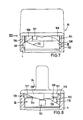
- valve 2 has a resetting mechanism for automatically resetting the second valve element 22 from the second switching position (venting position Fig. 3,7,8) back to the first switching position (venting position, Fig. 1,5,6).
- This reset mechanism will be explained in the following in particular with reference to FIGS. 1,5,7,8 and 9.
- a reset ring 100 (corresponds to the individual part IX) is arranged in the housing 4, which on the one hand is displaceable in the axial direction and on the other hand rotatably in the circumferential direction in the housing 4.
- the reset ring 100 has two for example diametrically opposed, radial lugs 102, which each engage in an axial groove 104 in the interior of the housing 4 and are guided displaceably in the direction of the longitudinal axis 7 of the valve.
- a prestressed compression spring 106 (see FIGS.
- the rotary knob 84 preferably has two diametrically opposed cams 108 which extend axially in the direction of the reset ring 100 and which rest on an axially opposite, circumferential cam surface 110 of the reset ring 100.
- FIG. 9 A development of the return ring 100 or the cam surface 110 is shown in FIG. 9. From this it can be seen that the cam surface 110 has two identical sections, each of which, starting from a locking recess 112 arranged at 0 ° or 180, extends over an angular range of approximately 30 perpendicular to the longitudinal axis 7 of the valve, relative to the locking recess 112 in the direction of Rotary knob 84 has a slightly offset region 114 as well as an inclined surface 116 which adjoins this region 114 and extends over an angular range of approximately 60 in a direction inclined away from the rotary knob 84, the inclined surface 116 extending further away from the rotary knob 84 in the axial direction stretches as the locking recess 112 and ends at a stop edge 118 which extends essentially parallel to the longitudinal axis 7.
- the stop edge 118 is adjoined by a region 120 which extends over an angular range of approximately 70 perpendicular to the longitudinal axis 7 and which at 160 or 340 again merges into the latching recess 112.
- the area 120 is somewhat closer to the rotary knob 84 than the area 114.
- the reset mechanism now works as follows.
- the cams 108 of the rotary knob 84 are in abutment against the stop edges 118 at the lowest point of the inclined surfaces 116.
- the ventilation position By rotating the rotary knob 84 in the direction of the second switching position, the ventilation position, the cams 108 move in the direction of the arrow 122 over the cam surface 110, as a result of which, due to the inclined surfaces 116, the return ring 100 is displaced axially in the direction of the arrows 124 against the force of the spring 106, as a result of which its pretension increases.
- the cams 108 When the rotary knob 84 is turned further, the cams 108 initially move in the direction of the arrow 122 over the cam surface regions 114 until they engage in the latching depressions 112 in the second switching position.
- the return ring 100 moves back again somewhat in the axial direction against the direction of the arrow 124.
- the ventilation position is thus defined by the engagement of the cams 108 in the locking recesses 112.
- the rotary knob 84 only needs to be turned by an angle of approximately 30 until the cams 108 in the direction of the arrow 126 reach the areas of the inclined surfaces 116 from the recesses 112 via the cam surface regions 114.
- the return ring 100 is automatically axially in the direction of the rotary knob 84, i.e. moved back in the direction of the arrow 124a and, due to the inclined surfaces 116, the cams 108 moved further in the direction of the arrow 126, i.e. the knob 84 continues to be turned until the starting position is reached again, in which the cams 108 rest against the stop edges 118.
- the venting position is hereby achieved in any case if the rotary knob is turned at least 30.
- the remaining rotation of about 60 required to reach the venting position is advantageously carried out automatically due to the reset mechanism according to the invention, so that the valve of the present invention also meets the highest safety requirements
- the rotary knob 84 additionally has at least one, but preferably two diametrically opposite stop cams 127, each of which extends in the axial direction into a circumferential housing recess 128.
- Each housing recess 128 extends in the circumferential direction over less than 1800, so that it is delimited by two stop edges 129.
- the design and arrangement of the stop cams 127 and the stop edges 129 is according to the invention such that the stop cams 127 abut one of the two stop edges 129 in each of the two switching positions of the valve according to the invention, which advantageously reinforces the latching action between the cams 108 and the cam surface 110 will, ie the two switching positions of the switching valve are defined even more clearly.
- the invention can also be implemented with any other valves, for example with 2/2-way valves. It is only essential that the system pressure acts on the surface of the second valve element (control disk) facing away from the first valve element (distributor disk), so that the second valve element is pressed against the first valve element seated firmly in the housing.
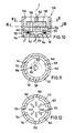
- a valve 130 which in turn has two disk-shaped valve elements in a valve housing 132 or in its housing chamber 134, namely a first valve element 136 and a second valve element 138.
- the housing chamber 134 is preferably cylindrical with a bottom 140 perpendicular to the longitudinal axis 7 of the valve.
- the first valve element 136 is rotatably independent of the second valve element 138 and is held in the housing 132 in the axial direction
- the second valve element 138 is rotatably supported relative to the first valve element 136 by means of an only indicated driver element 142.
- the housing chamber 134 is closed in a manner analogous to FIGS. 1 to 9 by a closure part, not shown in FIG. 10.
- a channel 144 connected to a pressure medium source P opens into the housing chamber 134 in the radially outer region of the bottom 140.
- the first valve element 136 has at least one axial slot opening 146 on its outer circumference in the region of the mouths of this pressure channel 144, as a result of which a pressure medium Via the channel 144 and the slot opening 146, axially past the two valve elements 136, 138 into the area above the second valve element 138, which in turn has a smaller diameter than the first valve element 136, and here again the surface facing away from the first valve element 136 surface of the second valve element.
- the second valve element 138 is thereby pressed against the first valve element 136 by the system pressure, which always ensures the desired “zero gap” between the valve elements 136 and 138.
- the first valve element 136 preferably consists of a circular disk part 148 with radial projections 150, between which the slot openings 146 are formed in each case.
- the first valve element 136 has in the circular disk part 148 a plurality of through openings 152 lying on a circle concentric with the longitudinal axis 7 and preferably arranged uniformly distributed over the circumference a common channel 156 leading to a consumer A opens.
- the second valve element 138 has only one through opening 158, which is arranged such that when the second valve element 138 rotates, it can be made to coincide with each of the through openings 152 of the first valve element 136, at least in regions.
- the through openings 152 and 158 can be formed with different cross-sectional shapes.
- the through openings 152 of the first valve element 136 according to FIG. 11 are circular and according to FIG. 12 in the form of radially arranged elongated holes.
- the passage opening 158 of the second valve element 138 is also designed, for example, as an elongated hole.
- valve 130 is particularly suitable for use in a so-called cascade connection, the second valve element 138 being driven by means of a motor drive, in particular by means of a stepping motor.
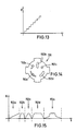
- the existing in a consumer A output pressure P receives a those shown in Fig. 13, zeitilchen course, that the pressure P rises a stepped manner on.
- the course of the stair-shaped rise can additionally be controlled by appropriate shapes of the through openings 152 and / or 158.
- Various alternatives for through openings 152 are indicated in FIG. 14.
- the through opening 152a has a triangular cross section
- the through opening 152b has a radially arranged elongated hole cross section
- the through opening 152c has a circular cross section
- the through opening 152d has a longitudinally curved cross section
- the through opening 152e has a circular cross section with two circumferentially extending, tapering sections.
- the diagram according to FIG. 15 shows the respective flow of the flow rate Q of a pressure medium over the rotation path s of the valve element 138.
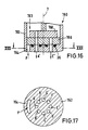
- the valve 160 illustrated in FIGS. 16 and 17 has in its housing 162 a pressure channel 164 opening into the housing chamber 163 analogous to the embodiment according to FIG. 10, but with a large number of output channels, for example eight output channels A ', B', C ', D', E ', F', G 'and H' (see the section in Fig. 17).
- the first valve element 166 is formed in the area of its outer circumference analogously to the embodiment according to FIG. 10 and has through openings which are aligned with the mouths of the outlet channels A 'to H'.
- the design of the second valve element 168 corresponds to that according to FIG. 10.
- the output channels A 'to H' can be selectively connected to the pressure channel 164, so that one of several consumers can optionally be activated.
- the second valve element 168 is pressed against the first valve element 166 by the system pressure.
Description
Eine erste Erfindung betrifft gemäß dem Oberbegriff des Patentanspruchs 1 ein Schaltventil zum Steuern insbesondere von pneumatischen Druckmedien, bestehend aus einem Gehäuse mit einem mit einem Systemdruck beaufschlagbaren Eingangskanal und mindestens einem Ausgangskanal sowie mit zwei in einer Gehäusekammer angeordneten, scheibenförmigen, im Betriebszustand unter einer Anpreßkraft dichtend aufeinanderliegenden, vorzugsweise aus Keramikmaterial bestehenden Ventilelementen, wobei das erste Ventilelement ortsfest in der Gehäusekammer gelagert und das zweite Ventilelement derart zwischen mindestens zwei Schaltstellungen verdrehbar in der Gehäusekammer angeordnet ist, daß die Eingangs- und Ausgangskanäle alle oder paarweise miteinander verbindbar bzw. gegeneinander absperrbar sind, wobei jeder Eingangs- bzw. Ausgangskanal des Gehäuses in eine Durchgangsöffnung des ersten, ortsfesten Ventilelementes übergeht und die Verbindung von jeweils mindestens zwei der Kanäle des Gehäuses über das zweite, die Durchgangsöffnungen des ersten Ventilelementes überdeckende und dabei in Abhängigkeit von der Schaltstellung zumindest paarweise verbindende Ventilelement erfolgt. Hierbei ist es wesentlich, daß alle unmittelbar mit den Gehäusekanälen verbundenen Durchgangsöffnungen des ortsfesten Ventilelementes von dem beweglichen Ventilelement überdeckt werden, wodurch das Druckmedium in allen Schaltstellungen des Ventils jeweils nur über Öffnungen der Ventilelemente geführt wird.A first invention relates, according to the preamble of claim 1, to a switching valve for controlling, in particular, pneumatic pressure media, consisting of a housing with an input channel to which system pressure can be applied and at least one output channel and with two disk-shaped arranged in a housing chamber and sealing in the operating state under a pressing force Valve elements lying one on top of the other, preferably made of ceramic material, the first valve element being mounted stationary in the housing chamber and the second valve element being rotatably arranged in the housing chamber between at least two switching positions in such a way that the input and output channels can be connected to one another or in pairs or can be blocked against one another, wherein each input and output channel of the housing merges into a through opening of the first, stationary valve element and the connection of at least two of the channels of the housing It is carried out via the second valve element, which covers the through openings of the first valve element and at least in pairs, depending on the switching position. It is essential here that all through openings of the stationary valve element which are directly connected to the housing channels are covered by the movable valve element, as a result of which the pressure medium in all switching positions of the valve is only guided through openings of the valve elements.
Ein derartiges Schaltventil ist aus der DE-A-3539316 bekannt. Die scheibenförmigen Ventilelemente derartiger Schaltventile weisen extrem glatte Oberflächen auf, mit denen sie aufeinanderliegend in innigem Kontakt miteinanderstehen. Hierdurch werden die Ventilelemente aufgrund von auftretenden Adhäsionskräften zusammengehalten, wodurch sich eine Dichtwirkung zwischen den Ventilelementen ergibt, diese aber dennoch gegeneinander verdrehbar und/oder verschiebbar sind. Um ein Auseinanderdrücken der Ventilelemente durch den Systemdruck, der z.B. in pneumatischen Bremssystemen von Kraftfahrzeugen bis zu 20 bar betragen kann, zu verhindern und hierdurch ebenfalls ein Eintreten von Schmutz in den sich zwischen den Ventilelementen bildenden Spalt auszuschließen, ist bei dem bekannten Ventil vorgesehen, daß die Ventilelemente mit einer bestimmten Anpreßkraft gegeneinander gepreßt werden, und zwar wird hier mechanisch eine Vorspannung z.B. durch gummielastische Druck- bzw. Dichtungselemente erzeugt. Dies bedeutet, daß die als "Paket-Einheit" aufeinanderliegenden Ventilelemente mit einer von den Druckelementen bestimmten Kraft gegeneinander gepreßt werden. Es hat sich jedoch gezeigt' daß bei hohen Systemdrücken z.B. von über 6 bar die mechanischen Druck- bzw. Dichtungselemente aufwendig und hiermit die auftretenden Trennkräfte schwer zu beherrschen sind. Weiterhin ist zwar bei dem bekannten Ventil die Höhe der Anpreßkraft bereits einstellbar, allerdings muß diese Einstellung anhand der zu erwartenden Druckwerte manuell vorgenommen werden. Nachteilig ist hierbei, daß Systemdruckänderungen, wie z.B. auftretende Druckspitzen, während des Betriebs des Schaltventils bei der Einstellung nicht berücksichtigt werden können, was folglich zu Dichtungsproblemen durch einen auftretenden Spalt zwischen den Ventilelementen führen kann.Such a switching valve is known from DE-A-3539316. The disk-shaped valve elements of such switching valves have extremely smooth surfaces with which they are in intimate contact with one another, lying on top of one another. As a result, the valve elements are held together due to the adhesive forces that occur, which results in a sealing effect between the valve elements, but these are nevertheless rotatable and / or displaceable relative to one another. In order to push the valve elements apart by the system pressure, e.g. In pneumatic brake systems of motor vehicles can be up to 20 bar, and thereby also prevent dirt from entering the gap formed between the valve elements, the known valve provides that the valve elements are pressed against one another with a certain contact pressure, and although a mechanical pre-tension is used here, for example generated by rubber-elastic pressure or sealing elements. This means that the valve elements lying on top of one another as a “package unit” are pressed against one another with a force determined by the pressure elements. However, it has been shown that at high system pressures e.g. The mechanical pressure and sealing elements are more complex than 6 bar and the resulting separation forces are difficult to control. Furthermore, the amount of contact pressure can already be set in the known valve, but this setting must be made manually on the basis of the pressure values to be expected. The disadvantage here is that system pressure changes, e.g. pressure peaks occurring during the operation of the switching valve can not be taken into account in the setting, which can consequently lead to sealing problems due to a gap occurring between the valve elements.
Aus der US-A-1 715 765 ist im Zusammenhang mit einer Druckluft-Bremsvorrichtungein insofern nicht gattungsgemäßes Drehschieberventil bekannt, als dieses ein scheibenförmiges Ventilelement (Drehschieber) aufweist, welches unmittelbar auf der Innenfläche einer Gehäuseplatte ("Ventilsitz" genannt) aufliegt, dabei aber nicht alle Kanäle der - prinzipiell ein "ortsfestes Ventilelement" bildenden - Gehäuseplatte überdeckt. Vielmehr mündet der Druck-Eingangskanal "außerhalb" des Drehschiebers in den Gehäuseinnenraum, der hierdurch ständig unter Druck steht, wodurch der Drehschieber durch Druckbeaufschlagung in Anlage an der Gehäuseplatte gehalten werden soll. Allerdings ist hierdurch der Gehäuseinnenraum in bestimmten Schaltstellungen auch Teil des Strömungsweges, wodurch es zu strömungsbedingten (dynamischen) Druckänderungen kommen kann.From US-A-1 715 765, in connection with a compressed air braking device, a rotary slide valve not of the generic type is known in that it has a disk-shaped valve element (rotary slide valve) which rests directly on the inner surface of a housing plate (called a "valve seat"), but at the same time not all channels of the housing plate - which in principle forms a "stationary valve element" - are covered. Rather, the pressure input channel "outside" of the rotary valve opens into the interior of the housing, which is thereby constantly under pressure, as a result of which the rotary valve is to be held in contact with the housing plate by pressurization. However, as a result, the interior of the housing is also part of the flow path in certain switching positions, which can lead to flow-related (dynamic) pressure changes.
Die DE-A-32 40 832 beschreibt ein ebenfalls nicht gattungsgemäßes Umschaltventil mit zwei scheibenförmigen Keramik-Ventilelementen, und zwar einer ortsfest gelagerten Scheibe und einer drehbaren Scheibe. Über die Erzeugung einer die beiden Scheiben in Anlage haltenden Anpreßkraft ist in dieser Veröffentlichung explizit nichts offenbart. In den Gehäuseinnenraum mündet in einem "oberhalb" der beweglichen Ventilscheibe liegenden Bereich unmittelbar ein Anschlußstutzen, der mit einer Druckleitung verbunden sein soll. Der Innenraum bildet folglich auch hier jeweils einen Teil des Strömungsweges.DE-A-32 40 832 describes a likewise non-generic changeover valve with two disk-shaped ceramic valve elements, namely a stationary disk and a rotatable disk. Nothing is explicitly disclosed in this publication about the generation of a contact pressure holding the two disks in contact. A connection piece, which is to be connected to a pressure line, opens directly into the interior of the housing in an area "above" the movable valve disk. The interior therefore also forms part of the flow path here.
Der Erfindung liegt "Zusatz X" die Aufgabe zugrunde, das bekannte Schaltventil der gattungsgemäßen Art so zu verbessern, daß sich die Höhe der die Ventilelemente gegeneinander pressenden Anpreßkraft automatisch an den jeweiligen Systemdruck anpaßt und daß sich zur Erzeugung der Anpreßkraft mechanische Druckelemente i.w. erübrigen können.The invention is based "Addition X" the task of improving the known switching valve of the generic type so that the amount of the pressing force pressing the valve elements against each other automatically adapts to the respective system pressure and that mechanical pressure elements i.w. can spare.
Erfindungsgemäß wird dies gemäß dem kennzeichnenden Teil des Patentanspruchs 1 dadurch erreicht, daß das zweite, bewegliche Ventilelement mindestens eine derart Kreisringsegmentförmige Durchgangsöffnung besitzt, die in jeder Schaltstellung zumindest teilweise die mit dem Eingangskanal verbundene Durchgangsöffnung des ersten Ventilelementes sowie in mindestens eine der Schaltstellungen zusätzlich mindestens eine der anderen Durchgangsöffnungen überdeckt, so daß zur Erzeugung der Anpreßkraft das zweite Ventilelement auf seiner dem ersten Ventilelement abgekehrten Oberfläche in jeder Schaltstellung mit dem in dem Eingangskanal herrschenden Systemdruck des Druckmediums beaufschlagt ist. Vorteilhafte Weiterbildungen der Erfindung sind in den vom Anspruch 1 abhängigen Ansprüchen enthalten.According to the invention, this is achieved in accordance with the characterizing part of patent claim 1 in that the second, movable valve element has at least one annular segment segment of this type Has passage opening, which in each switching position at least partially covers the passage opening of the first valve element connected to the input channel and in at least one of the switching positions additionally at least one of the other passage openings, so that in order to generate the contact pressure, the second valve element on its surface facing away from the first valve element in each Switch position with the system pressure of the pressure medium prevailing in the input channel. Advantageous developments of the invention are contained in the claims dependent on claim 1.
Erfindungsgemäß wird somit eine Durchgangsverbindung geschaffen, die stets, d.h. in jeder Schaltstellung des Ventils, den von dem ortsfesten Ventilelement bzw. von dessen entsprechender Durchgangsöffnung überdeckten Druck-Eingangskanal derart mit dem Raum "oberhalb" des beweglichen Ventilelementes verbindet, daß die Ventilelemente unmittelbar von dem Systemdruck gegeneinander gepreßt werden, da ja eine Wirkung des Druckes auf die aneinanderliegenden Oberflächen der Ventilelemente aufgrund der Dichtwirkung ausgeschlossen ist. Erfindungsgemäß wird somit der Systemdruck einzig und allein zum Zwecke der Erzeugung der Anpreßkraft auf die Seite der dem ersten, ortsfesten Ventilelement abgekehrten Oberfläche des zweiten, beweglichen Ventilelementes geleitet, so daß im Bereich der druckbeaufschlagten Oberfläche des beweglichen Ventilelementes stets im wesentlichen statische Verhältnisse des Druckmediums vorliegen, weil in diesem Bereich praktisch keine Strömung auftritt. Daher sind die Druckverhältnisse hier weitgehend konstant, zumindest treten keine strömungsbedingten Druckabfälle des statischen Anpreßdruckes auf, so daß entsprechendes vorteilhafterweise auch für die resultierende Anpreßkraft gilt. Auf diese Weise wird auch oder vielmehr gerade bei hohen Systemdrücken stets ein "Null-Spalt" zwischen den Ventilelementen gewährleistet, so daß Verschmutzungen der Dichtfläche zwischen den Ventilelementen nahezu völlig ausgeschlossen sind. Von besonderem Vorteil ist, daß sich die Anpreßkraft zwischen den Ventilelementen selbsttätig mit dem Systemdruck einstellt, d.h. je höher der Systemdruck desto höher auch die Anpreßkraft und damit auch die Sicherheit gegen ein druckbedingtes Auseinanderdrücken der Ventilelemente. Hierdurch werden auftretende Druckänderungen während des Betriebs des erfindungsgemäßen Schaltventils vorteilhafterweise selbsttätig ausgeglichen. Auftretende Druckspitzen sind ebenfalls unschädlich, da sich hierdurch auch kurzzeitig die Anpreßkraft erhöht.According to the invention, a through connection is thus created which always, i.e. In each switching position of the valve, the pressure input channel covered by the stationary valve element or by its corresponding through opening connects with the space "above" the movable valve element in such a way that the valve elements are pressed directly against one another by the system pressure, since an effect of the pressure on the adjacent surfaces of the valve elements due to the sealing effect is excluded. According to the invention, the system pressure is therefore directed solely to the side of the surface of the second, movable valve element facing away from the first, stationary valve element for the purpose of generating the contact pressure, so that essentially static conditions of the pressure medium are always present in the area of the pressurized surface of the movable valve element because there is practically no flow in this area. Therefore, the pressure conditions are largely constant here, at least there are no flow-related pressure drops in the static contact pressure, so that the corresponding advantageously also applies to the resulting contact pressure. In this way, even at high system pressures, a "zero gap" between the valve elements is always guaranteed, so that contamination of the sealing surface between the valve elements is almost completely excluded. It is particularly advantageous that the contact pressure between the valve elements adjusts itself automatically with the system pressure, i.e. the higher the system pressure, the higher the contact pressure and thus also the security against pressure-related pushing apart of the valve elements. As a result, pressure changes occurring during the operation of the switching valve according to the invention are advantageously automatically compensated. Pressure peaks that occur are also harmless, since this also increases the contact pressure for a short time.
Eine weitere Erfindung betrifft gemäß dem Oberbegriff des Patentanspruchs 5 ein Schaltventil zum Steuern insbesondere von pneumatischen Druckmedien, bestehend aus einem Gehäuse mit mindestens einem Druck-Eingangskanal und mindestens einem Ausgangskanal sowie mit mindestens zwei in einer Gehäusekammer angeordneten, scheibenförmigen, im Betriebszustand unter einer Anpreßkraft dichtend aufeinanderliegenden, vorzugsweise aus Keramikmaterial bestehenden Ventilelementen, von denen mindestens eines derart verdrehbar und/oder verschiebbar in der Gehäusekammer angeordnet ist, daß die Eingangs- bzw. Ausgangskanäle alle und/oder paarweise miteinander verbindbar sind, wobei zur Erzeugung der Anpreßkraft zumindest eines der Ventilelemente auf seiner dem anderen Ventilelement abgekehrten Oberfläche von dem Druckmedium beaufschlagt ist.A further invention relates, according to the preamble of claim 5, to a switching valve for controlling, in particular, pneumatic pressure media, consisting of a housing with at least one pressure input channel and at least one output channel and with at least two disk-shaped arranged in a housing chamber, sealing in the operating state under a contact pressure Valve elements lying one on top of the other, preferably made of ceramic material, at least one of which is rotatably and / or displaceably arranged in the housing chamber such that the input and output channels can all be connected to one another and / or in pairs, with at least one of the valve elements being used to generate the contact pressure its surface facing away from the other valve element is acted upon by the pressure medium.
Ein derartiges Schaltventil ist beispielsweise in der US-A-1 715 765 im Zusammenhang mit einer Druckluft-Bremsvorrichtung beschrieben. Ein scheibenförmiger Drehschieber bildet das bewegliche Ventilelement, welches unmittelbar auf einer Kanäle aufweisen Gehäuseplatte Ventilsitz) aufliegt, die somit praktisch das ortsfeste Ventilelement bildet. Zur Betätigung des Drehschiebers ist mit diesem über eine Welle ein Handhebel verbunden. Damit muß das Ventil manuell in die jeweilige Schaltstellung geschaltet werden.Such a switching valve is described for example in US-A-1 715 765 in connection with a compressed air braking device. A disk-shaped rotary valve forms the movable valve element, which rests directly on a channel (housing plate valve seat), which thus practically forms the stationary valve element. To operate the rotary valve, a hand lever is connected to it via a shaft. The valve must therefore be switched manually to the respective switching position.
Diese weiteren Erfindung liegt die Aufgabe zugrunde, bei einem gattungsgemäßen Ventil den Schaltvorgang, insbesondere das Zurückschalten von einer zweiten Schaltstellung in eine erste Schaltstellung, wesentlich zu erleichtern, wobei die jeweilige Schaltstellung auch sehr genau definiert erreicht werden soll, so daß das Ventil auch höchsten Sicherheitsanforderungen genügt.This further invention is based on the object, in a generic valve, to simplify the switching process, in particular the downshifting from a second switching position to a first switching position, the respective switching position also being to be achieved in a very precisely defined manner, so that the valve also meets the highest safety requirements enough.
Erfindungsgemäß wird dies gemäß dem kennzeichnenden Teil des Patentanspruchs 5 durch einen Rückstellungsmechanismus erreicht, der das das zweite Ventilelement ausgehend von einer zweiten Schaltstellung nach geringfügigem manuellen Verdrehen selbsttätig weiter bis in eine erste Schaltstellung zurückverdreht. Vorteilhafte Weiterbildungen der Erfindung sind in den vom Anspruch 5 abhängigen Ansprüchen enthalten.According to the invention, this is achieved according to the characterizing part of patent claim 5 by a reset mechanism which automatically rotates the second valve element further from a second switch position after a slight manual rotation to a first switch position. Advantageous developments of the invention are contained in the claims dependent on claim 5.
Durch den erfindungsgemäßen Rückstellungsmechanismus braucht das bewegliche Ventilelement ausgehend von der zweiten Schaltstellung, bei der es sich vorzugsweise um eine sogenannte Belüftungsstellung handelt (Verbraucheranschluß mit Druckanschluß verbunden), manuell lediglich geringfügig; beispielsweise um 30°, verdreht zu werden. Das weitere Verdrehen um beispielsweise weitere 60 bis in die erste Schaltstellung, vorzugsweise in eine sogenannte Entlüftungsstellung (Verbraucheranschluß mit Entlüftung verbunden), erfolgt dann vorteilhafterweise automatisch durch den erfindungsgemäßen Rückstellungsmechanismus. In der bevorzugten Ausführungsform bedeutet dies, daß die Entlüftungsstellung jedenfalls "zwangsweise" erreicht wird, so daß eine hohe Sicherheit gewährleistet ist.By means of the reset mechanism according to the invention, starting from the second switching position, which is preferably a so-called ventilation position (consumer connection connected to pressure connection), the movable valve element needs only a slight manual change; for example, to be rotated by 30 ° . The further rotation, for example, by a further 60 to the first switching position, preferably in a so-called venting position (consumer connection connected to venting), is then advantageously carried out automatically by the reset mechanism according to the invention. In the preferred embodiment means this means that the venting position is in any case "forced" so that a high level of safety is guaranteed.
Anhand der Zeichnung werden im folgenden die Erfindungen beispielhaft näher erläutert. Dabei zeigen:
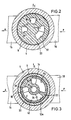
- Fig. 1 einen Teil-Längsschnitt durch ein erfindungsgemäßes Schaltventil in einer ersten Schaltstellung,
- Fig. 2 einen Querschnitt längs der Linie 11-11 in Fig. 1,
- Fig. 3 einen Querschnitt längs der Linie 111-111 in Fig. 1, jedoch in einer zweiten Schaltstellung,
- Fig. 4 einen Querschnitt längs der Linie IV-IV in Fig. 1,
- Fig. 5 einen Teil-Längsschnitt durch das erfindungsgemäße Schaltventil in einer gegenüber Fig. 1 um 90 versetzten Ebene ebenfalls in der ersten Schaltstellung,
- Fig. 6 einen Querschnitt längs der Linie VI-VI in Fig. 5,
- Fig. 7 eine teilgeschnittene Ansicht des oberen Bereichs des Schaltventils analog zu Fig. 5, jedoch in der zweiten Schaltstellung,
- Fig. 8 eine teilgeschnittene Ansicht in Pfeilrichtung VIII in Fig. 7,
- Fig. 9 eine Mantelflächenabwicklung eines Einzelteils IX in Fig. 7 und 8,
- Fig. 10 einen Teil-Längsschnitt einer weiteren Ausführungsform eines erfindungsgemäßen Schaltventils,
- Fig. 11 einen Querschnitt längs der Linie XI-XI in Fig. 10,
- Fig. 12 einen Querschnitt längs der Linie XII-XII in Fig. 10,
- Fig. 13 ein Diagramm zur Darstellung des zeitlichen Verlaufs des Ausgangsdruckes Pa des Ventils gemäß Fig. 10 bis 12,
- Fig. 14 eine Draufsicht eines zu Fig. 10 bis 12 alternativen Ventilelementes,
- Fig. 15 Diagramme zur Darstellung der durch das Ventil strömenden Druckmittelmenge Q in Abhängigkeit von der Drehstellung s,
- Fig. 16 einen Teil-Längsschnitt einer weiteren Ausführungsform eines erfindungsgemäßen Ventils und
- Fig. 17 einen Schnitt längs der Linie XVII-XVII in Fig. 16.
- 1 is a partial longitudinal section through a switching valve according to the invention in a first switching position,
- 2 shows a cross section along the line 11-11 in FIG. 1,
- 3 shows a cross section along the line 111-111 in FIG. 1, but in a second switching position,
- 4 shows a cross section along the line IV-IV in FIG. 1,
- 5 shows a partial longitudinal section through the switching valve according to the invention in a plane offset by 90 compared to FIG. 1, likewise in the first switching position,
- 6 shows a cross section along the line VI-VI in FIG. 5,
- 7 is a partially sectioned view of the upper region of the switching valve analogous to FIG. 5, but in the second switching position,
- 8 is a partially sectioned view in the direction of arrow VIII in Fig. 7,
- 9 shows a lateral surface development of an individual part IX in FIGS. 7 and 8,
- 10 is a partial longitudinal section of a further embodiment of a switching valve according to the invention,
- 11 is a cross section along the line XI-XI in Fig. 10,
- 12 is a cross section along the line XII-XII in Fig. 10,
- 13 is a diagram showing the time course of the outlet pressure P a of the valve according to FIGS. 10 to 12,
- 14 is a plan view of an alternative valve element to FIGS. 10 to 12,
- 15 shows diagrams to illustrate the pressure medium quantity Q flowing through the valve as a function of the rotational position s,
- 16 shows a partial longitudinal section of a further embodiment of a valve according to the invention and
- FIG. 17 shows a section along the line XVII-XVII in FIG. 16.
Bei dem in Fig. 1 und 5 dargestellten Schaltventil handelt es sich beispielhaft um ein 3/2-Wegeventil 2 insbesondere für pneumatische Druckmedien, z.B. Druckluft. Das Ventil 2 besitzt ein Gehäuse 4 vorzugsweise aus Kunststoff mit einer i.w. zylindrischen, einseitig offenen Gehäusekammer 6. In ihrem der offenen Seite gegenüberliegenden Bereich ist die Gehäusekammer 6 von einem zur Ventil-Längsachse 7 senkrechten Boden 8 begrenzt, in dessen Bereich drei Kanäle 10 und 12 (Fig. 1) sowie 14 (Fig. 5) in die Gehäusekammer 6 münden. Wie aus dem Schnitt in Fig. 2 zu erkennen ist, besitzen die Kanäle 10, 12 und 14 zumindest in ihrem Mündungsbereich jeweils einen Querschnitt in Form eines Kreisringsegmentes, wobei alle drei Kreisringsegmente auf einem gemeinsamen, gedachten, zu der Längsachse 7 konzentrischen Kreisring liegen. Die Kanäle 10, 12, 14 bzw. deren Mündungen sind jeweils um ca. 90 zueinander versetzt, wobei sich die Kanäle 10 und 12 diametral gegenüberliegen. Die Mündung jedes Kanals 10, 12, 14 überdeckt in Umfangsrichtung einen Winkelbereich von etwa 30 ° . Die Kanäle 10 und 12 verlaufen durch schräg zur Längsachse 7 angeordnete Anschlußstutzen 16 und 18 des Gehäuses 4, wobei an die Anschlußstutzen 16, 18 nicht dargestellte Druckmittelleitungen anschließbar sind, die zu einer Druckmittelquelle P bzw. zu einem Verbraucher A führen. Der dritte Kanal 14 kann im Falle des pneumatischen Ventils zur Entlüftung E einfach nach außen offen sein, während der Kanal 14 bei einem für hydraulische Medien vorgesehenen Ventil über eine Leitung mit einem Druckmitteltank verbunden wäre.The switching valve shown in Figs. 1 and 5 is an example of a 3/2-
Das erfindungsgemäße Ventil 2 dient nun dazu, in einer ersten Schaltstellung, der sog. Entlüftungsstellung (Fig. 1 und 5), den Verbraucher A bzw. den Kanal 10 mit dem nach außen oder zu einem Druckmitteltank führenden Kanal 14 zu verbinden und den zu der Druckmittelquelle P führenden Kanal 12 zu verschließen. In einer zweiten Schaltstellung, der sog. Belüftungsstellung (Fig. 7 und 8), sollen der Verbraucher A bzw. der Kanal 10 mit der Druckmittelquelle P bzw. mit dem Kanal 12 verbunden und der Entlüftungskanal 14 verschlossen werden.The
Zu diesem Zweck sind in der Gehäusekammer 6 zwei scheibenförmige Ventilelemente 20,22 angeordnet, die vorzugsweise aus Keramikmaterial, oder aber aus einem geeigneten Kunststoff bzw. einer Keramik-Kunststoff-Kombination bestehen. Die beiden Ventilelemente 20 und 22 stehen miteinander in direktem stirnseitigen Kontakt, wodurch sich aufgrund ihrer äußerst glatten Oberflächen und einer hierdurch auftretenden Adhäsionswirkung zwischen den Ventilelementen 20, 22 eine Dichtfläche 24 ergibt, ohne daß zusätzliche Dichtungen erforderlich wären.For this purpose, two disk-shaped
Das dem Boden 8 der Gehäusekammer 6 nächstliegende Ventilelement 20 dient als Verteilerscheibe und ist verdrehsicher in dem Gehäuse 4 gelagert, wozu auf dem Boden 8 vorzugsweise zwei zapfenartige Vorsprünge 26 (siehe Fig. 4) angeordnet sind, die formschlüssig in entsprechende Aufnahmevertiefungen (in der Zeichnung nicht zu erkennen) auf der dem Boden 8 zugekehrten Seite des Ventilelementes 20 eingreifen. Wie ausThe
Fig. 1 und 2 deutlich wird, besitzt das Ventilelement 20 eine mit dem Verbraucher-Kanal 10 fluchtende Durchgangsöffnung 28 und eine mitdem Entlüftungs-Kanal 14 fluchtende Durchgangsöffnung 30. Diese Durchgangsöffnungen 28 und 30 besitzen jeweils eine zu den Kanälen 10, 14 i.w. kongruente Form, d.h. sie sind ebenfalls kreisringsegmentförmig ausgebildet, wobei sie in Umfangsrichtung ebenfalls einen Winkelbereich von jeweils etwa 30 überdecken. Im Bereich des Druck-Kanals 12 besitzt das Ventilelement 20 auf seiner dem Boden 8 der Gehäusekammer 6 zugekehrten Seite eine kreisringsegmentförmige Vertiefung 32 mit zwei zur Längsachse 7 parallelen Wandungen und einem zu diesen senkrechten Boden (Fig. 1), wobei sich die Vertiefung 32 ausgehend von ihrem den Druck-Kanal 12 überdeckenden Endbereich in Umfangsrichtung von dem Entlüftungskanal 14 weg und auf den Verbraucher-Kanal 10 zu erstreckt (siehe Fig. 2), und zwar überdeckt die Vertiefung 32 einen Winkelbereich von etwa 90°. Wie aus den Schnittansichten nach Fig. 3 und 6 zu erkennen ist, besitzt das Ventilelement 20 in dem in Umfangsrichtung der den Verbraucherkanal 10 überdeckenden Durchgangsöffnung 28 zugekehrten Endbereich der Vertiefung 32 eine Durchgangsöffnung 34, deren Form den Durchgangsöffnungen 28 und 30 entspricht Aufgrund dieser beschriebenen Ausgestaltung ist die Mündung des Druck-Kanals 12 praktisch über das Ventilelement 20, d.h. über die Vertiefung 32 und die Durchgangsöffnung 34, in umfänglicher Richtung auf den Verbraucher- Kanal 10 zu sowie von dem Entlüftungs-Kanal 10 weg versetzt, und zwar um einen Winkel von etwa 600, was insbesondere in Fig. 6 zu erkennen ist, da hier die Mündung des Kanals 12 gestrichelt eingezeichnet ist. Die Durchgangsöffnung 34 des Ventilelementes 20 stellt somit die eigentliche Mündung des Kanals 12 auf der dem anderen Ventil 22 zugekehrten Seite des Ventilelementes 20 dar, was durch die Bezugsziffer 12a angedeutet werden soll.1 and 2 it becomes clear, the
Wie insbesondere in Fig. 1, 4 und 6 zu erkennen ist, ist zwischen dem Boden 8 der Gehäusekammer 6 und dem Ventilelement 20 eine Profildichtung 36 angeordnet, die gemäß Fig. 4 zur gegenseitigen Abdichtung der Kanäle 10, 12 und 14 deren Mündungen jeweils umschließt. Die Profildichtung 36 besteht aus einem äußeren Ring 36a, der alle Kanäle 10, 12, 14 gemeinsam umschließt. Ausgehend von dem Ring 36a erstrecken sich jeweils beidseitig neben dem Verbraucher-Kanal 10 und dem Entlüftungs-Kanal 14 Dichtungsabschnitte 36b etwa radial nach innen und sind über einen Verbindungsabschnitt 36c miteinander verbunden. Zwischen den Kanälen 10 und 14 besitzt die Profildichtung 36 eine Öffnung 36d, in die ein auf dem Boden 8 der Gehäusekammer 6 angeordneter Positionierungsansatz 38 eingreift, wodurch die Profildichtung 36 verdrehfest in dem Gehäuse 4 gehalten ist. Zum Positionieren des den Kanälen 10 und 14 etwa diametral gegenüberliegenden, flexiblen Bereichs des Ringes 36a dient eine Erhebung 40 des Bodens 8, die sich im dargestellten Beispiel auf einem Kreisbogen zwischen den das Ventilelement 20 verdrehfest haltenden Vorsprüngen 26 erstreckt. Zur zusätzlichen Positionierung der Profildichtung 36 können die Kanäle 10 und 14 von Stegen 39 umgeben sein, die sich axial von dem Boden 8 erstrecken und ihrerseits von der Profildichtung 36 umschlossen sind.As can be seen in particular in FIGS. 1, 4 and 6, a
Das zweite Ventilelement 22 dient als Steuerscheibe und ist hierzu relativ zu dem ersten, feststehenden Ventilelement 20 verdrehbar in dem Gehäuse 4 gelagert. Das zweite Ventilelement 22 besitzt einen geringeren Durchmesser als das erste Ventilelement 20, so daß letzteres radial nach außen mit einer ringförmigen Überstandsfläche 41 das zweite Ventilelement 22 überragt (siehe Fig. 1 und 5). Wie am besten in Fig. 3 und 6 zu erkennen ist, besitzt das zweite Ventilelement 22 erfindungsgemäß eine kreisringsegmentförmige Durchgangsöffnung 42, die sich in Umfangsrichtung über einen Winkelbereich von ca. 160 erstreckt. Ferner weist das Ventilelement 22 auf seiner dem anderen Ventilelement 20 zugekehrten Seite eine kreisringsegmentförmige Vertiefung 44 mit zur Längsachse 7 parallelen Wandungen und einem hierzu senkrechten Boden auf. Die Vertiefung 44 erstreckt sich in Umfangsrichtung über einen Winkelbereich von ca. 1200. Die Durchgangsöffnung 42 ist in Umfangsrichtung gesehen einseitig um etwa 20 und anderseitig um etwa 60 ° von der Vertiefung 44 beabstandet. Die Durchgangsöffnung 42 und die Vertiefung 44 liegen ebenfalls wie die Mündungen der Kanäle 10,12,14 bzw. die Durchgangsöffnungen 28,30,34 des ersten Ventilelementes 20 auf dem gleichen gedachten, gemeinsamen, zur Längsachse 7 konzentrischen Kreisring, so daß sie die Kanäle, bzw. die Durchgangsöffnungen 28,30 und 34 des Ventilelementes 20 jeweils überdecken können. Schließlich besitzt das Ventilelement 22 eine zentrische, im Querschnitt kreisförmige Durchgangsöffnung 46, die einseitig durch das erste Ventilelement 20 verschlossen ist, und die sich in einer dem ersten Ventilelement 20 abgekehrten Richtung über eine Ringstufe 48 im Durchmesser verringert (Fig. 1 und 5).The
In der in Fig. 6 dargestellten ersten Schaltstellung, d.h. in der sog. Entlüftungsstellung, befindet sich das zweite Ventilelement 22 in einer Drehstellung, in der es mit der Vertiefung 44 die Durchgangsöffnungen 28 und 30 des ersten Ventilelementes 20 überdeckt und hierdurch den Verbraucher-Kanal 10 mit dem Entlüftungs-Kanal 14 verbindet, d.h. den Verbraucher A entlüftet. Die Durchgangsöffnung 42 des zweiten Ventilelementes 22 überdeckt dabei einen Bereich des ersten Ventilelementes 20, in dem nur die eigentliche Mündung 12a des Druck-Kanals 12, d.h. die Durchgangsöffnung 34 des ersten Ventilelementes 20, angeordnet ist, so daß folglich der Druck-Kanal 12 durch das Ventil 2 verschlossen ist.In the first switching position shown in FIG. 6, that is to say in the so-called venting position, the
In der in Fig. 3 dargestellten zweiten Schaltstellung, der sog. Belüftungsstellung, befindet sich dagegen das zweite Ventilelement 22 in einer gegenüber Fig. 6 um 90 verdrehten Drehstellung, in der es mit der Durchgangsöffnung 42 die eigentliche Mündung 12a des Druck-Kanals 12, d.h. die Durchgangsöffnung 34 des ersten Ventilelementes 20, sowie den Verbraucher-Kanal 10 bzw. die Durchgangsöffnung 28 des ersten Ventielementes 20 überdeckt und hierdurch den Verbraucher A mit dem Druck P verbindet (belüftet). Die Vertiefung 44 überdeckt nur die Durchgangsöffnung 30 des ersten Ventilelementes 20 bzw. den Entlüftungs-Kanal 14, der hierdurch verschlossen ist.In contrast, in the second switching position shown in FIG. 3, the so-called ventilation position, the
In beiden Fällen wird durch die erfindungsgemäße Ausgestaltung, und zwar insbesondere dadurch, daß die Durchgangsöffnung 42 des zweiten Ventilelementes 22 stets die eigentliche Mündung 12a des Druck-Kanals 12 überdeckt, erreicht, daß der Druck P in allen Ventilstellungen durch die Durchgangsöffnung 42 hindurch auf die dem ersten Ventilelement 20 abgekehrte Oberseite des zweiten Ventilelementes 22 wirken kann, wodurch dieses vorteilhafterweise gegen das erste Ventilelement 20 gepreßt wird, da ja eine Wirkung des Druckes auf die dem Ventilelement 20 zugekehrte Seite des Ventilelementes 22 aufgrund der Dichtwirkung zwischen den Ventilelementen 20,22 (Dichtfläche 24) ausgeschlossen ist. Auf diese Weise wird auch oder vielmehr gerade bei hohen Systemdrücken stets ein "Null-Spalt" zwischen den Ventilelementen 20 und 22 gewährleistet, so daß Verschmutzungen der Dichtfläche 24 nahezu völlig ausgeschlossen sind. Dabei ist von entscheidendem Vorteil, daß sich die Anpreßkraft des zweiten Ventilelementes gegen das erste Ventilelement 20 selbsttätig mit dem Systemdruck einregelt, d.h. je höher der Systemdruck desto höher auch die Anpreßkraft und damit auch die Sicherheit gegen ein druckbedingtes Auseinanderdrücken der Ventilelemente 20,22.In both cases, the configuration according to the invention, in particular in that the passage opening 42 of the
Zum Verdrehen des zweiten Ventilelementes 22 gegenüber dem feststehenden Ventilelement 20 ist in dem Gehäuse ein Mitnehmerelement 50 angeordnet. Wie am besten in Fig. 1 zu erkennen ist, besteht dieses Mitnehmerelement 50 aus einem parallel zu dem zweiten Ventilelement 22 auf dessen dem ersten Ventilelement 20 abgekehrten Seite angeordneten, kreisförmigen Scheibenteil 52, das auf seiner dem zweiten Ventilelement 22 zugekehrten Fläche mindestens einen in beiden Umfangsrichtungen formschlüssig in die Durchgangsöffnung 42 des zweiten Ventilelementes 22 eingreifenden, kreisringsegmentförmigen Mitnehmeransatz 54 aufweist. Vorzugsweise sind zwei kreisringsegmentförmige Mitnehmeransätze 54 vorgesehen, die jeweils in den Endbereichen der Durchgangsöffnung 42 an dem zweiten Ventilelement 22 zur Drehmitnahme anliegen, und zwischen denen in Umfangsrichtung ein Spalt verbleibt, über den in der oben beschriebenen Weise der Druck P durch die Durchgangsöffnung 42 hindurch die Oberseite des Ventilelementes 22 beaufschlagt. Der Scheibenteil 52 besitzt ferner einen zentrischen, einen axialen Schlitz 55 (s. Fig. 5) aufweisenden Rastansatz 56, der sich in die zentrische Durchgangsöffnung 46 des Ventilelementes 22 erstreckt und mit einer Rastkante 58 die Ringstufe 48 in der Durchgangsöffnung 46 rastend hintergreift, wobei der Rastansatz 56 aufgrund des axialen Schlitzes 55 in zwei radial federelastische Rastarme unterteilt ist. Der Rastansatz 56 ermöglicht eine einfache Montage des zweiten Ventilelementes 22, indem dieses über den Rastansatz 56 an dem Mitnehmerelement 50 vormontiert und zusammen mit diesem in die Gehäusekammer 6 eingesetzt wird. Der Rastansatz 56 ist konzentrisch von einer sich axial in den Scheibenteil 52 erstreckenden Ringnut 60 umgeben, in der eine als Spiralfeder ausgebildete Druckfeder 62 unter Vorspannung angeordnet ist, die sich einseitig im Grund der Ringnut 60 und anderseitig auf dem zweiten Ventilelement 22 abstützt. Hierdurch wird eine das zweite Ventilelement 22 gegen das erste Ventilelement 20 pressende Vorspannung erzeugt, die erfindungsgemäß zumindest so groß ist, daß sie dazu ausreicht, im drucklosen Zustand des Ventils 2 zwischen den beiden Ventilelementen 20 und 22 den erwähnten "Nullspalt" zu gewährieisten. Nach Druckbeaufschlagung wird dann durch die Erfindung die Wirkung der Feder 62 durch den Systemdruck unterstützt bzw. verbessert.A
Wie weiter aus Fig. 1 deutlich wird, schließt sich an den Scheibenteil 52 auf seiner dem Ventilelement 22 abgekehrten Seite in axialer Richtung ein weiterer, im Durchmesser reduzierter, flacher Scheibenteil 64 und an diesen ein zentrischer, zylindrischer Dichtungsansatz 66 mit einem gegenüber dem Scheibenteil 64 weiter reduzierten Durchmesser an. Der Dichtungsansatz 66 trägt in einer Ringnut einen Dichtring 68.1, on the side facing away from the
Die Gehäusekammer 6 ist durch ein Verschlußteil 70 druckdicht verschlossen. Dieses Verschlußteil 70 besteht aus zwei Hohlzylinderabschnitten 72 und 74 mit unterschiedlichen Durchmessern, die in radialer Richtung über einen Scheibenring 76 ineinander übergehen. Der dem Boden 8 der Gehäusekammer 6 zugekehrte, untere Hohlzylinderabschnitt 72 besitzt einen größeren Durchmesser als der andere, obere Hohlzylinderabschnitt 74, umschließt konzentrisch die beiden Scheibenteile 52 und 64 des Mitnehmerelementes 50 sowie das zweite Ventilelement 22 und sitzt mit einer stirnseitigen Ringfläche auf der oben bereits erwähnten Überstandsfläche 41 des ersten Ventilelementes 20 auf. Der obere Hohlzylinderabschnitt 74 umschließt konzentrisch den Dichtungsansatz 66 des Mitnehmerelementes 50, wobei der Dichtring 68 dichtend an der Innenumfangsfläche des oberen Hohlzylinderabschnittes 74 anliegt. Auf der Höhe des die beiden Hohlzylinderabschnitte 72 und 74 verbindenden Scheibenringes 76 weist das Verschlußteil 70 einen radial nach außen weisenden, umlaufenden Ringsteg 78 auf, der auf einer Ringstufe der Gehäusekammer 6 in axialer Richtung aufsitzend mit dem Gehäuse 4 stoffschlüssig verbunden, insbesondere ultraschallverschweißt ist. Aufdiese Weise ist die Gehäusekammer 6 durch das Verschlußelement 70 druckdicht verschlossen und zwar aufgrund der umfänglichen Verschweißung mit dem Gehäuse 4 im Bereich des Ringstegs 78 sowie aufgrund des den Spalt zwischen dem Mitnehmerelement 50 bzw. dem Dichtungsansatz 66 und dem oberen Hohlzylinderabschnitt. 74 abdichtenden Dichtringes 68. Der untere Hohlzylinderabschnitt. 72 des Verschlußteils 70 drückt nach dem Herstellen der Verbindung mit dem Gehäuse 4 im Bereich des Ringstegs 78 das erste Ventilelement 20 über die Überstandsfläche 41 axial in Richtung des Bodens 8 der Gehäusekammer 6 bzw. gegen die Profildichtung 36, die hierdurch zum gegenseitigen Abdichten der Kanäle 10, 12 und 14 vorgespannt wird. Durch die unlösbare Verbindung zwischen dem Verschlußteil 70 und dem Gehäuse 4 sitzt auch das drehbewegliche Mitnehmerelement 50 in axialer Richtung fest in dem Gehäuse 4, da es mit dem Scheibenteil 64 an der inneren Ringfläche des Scheibenrings 76 des Verschlußteils 70 zur Anlage kommt.The
An den Dichtungsansatz 66 des Mitnehmerelementes 50 schließt sich in axialer Richtung weiterhin ein Mitnehmerabschnitt 80 an, der einen von der Kreisform abweichenden, vorzugsweise quadratischen Querschnitt besitzt und formschlüssig in eine Mitnehmeraufnahme 82 eines sich axial an das Gehäuse 4 anschließenden Drehknopfes 84 eingreift. Zur Halterung des Drehknopfes 84 weist das aufgrund des Verschlußteils 70 in dem Gehäuse 4 gehaltene Mitnehmerelement 50 im axialen Anschluß an den Mitnehmerabschnitt 80 einen stiftförmigen Rastansatz 86 auf, der sich in eine axiale Öffnung 87 des Drehknopfes 84 erstreckt und mit einer Rastkante 88 eine Ringstufe 90 der Öffnung 87 hintergreift. Zu diesem Zweck weist der Rastansatz 86 einen axialen Schlitz 92 auf, wodurch er in zwei radial federelastische Rastanne unterteilt ist, die endseitig angefast sind. Es ist weiterhin vorteilhaft, wenn in die nach außen offene Öffnung 87 des Drehknopfes 84 von oben ein Sicherungsstift 94 axial eingesteckt ist, der mit einem Stiftabschnitt 96 zwischen die Rastarme des Rastansatzes 86 eingreift und diese somit in ihrer radial gespreizten Raststellung hält, wodurch der Drehknopf 84 gegen ein ungewolltes Lösen gesichert ist. Ein Lösen des Drehknopfes 84 ist dennoch möglich, indem zuvor der Sicherungsstift 94 entfernt wird.In addition to the sealing
In einer weiteren Ausgestaltung der Erfindung besitzt das Ventil 2 einen Rückstellmechanismus zum automatischen Rückstellen des zweiten Ventilelementes 22 von der zweiten Schaltstellung (Bolüftungsstellung Fig. 3,7,8) zurück in die erste Schaltstellung (Entlüftungsstellung, Fig. 1,5,6). Dieser Rückstellmechanismus soll im folgenden insbesondere unter Bezug auf die Fig. 1,5,7,8 und 9 erläutert werden.In a further embodiment of the invention, the
Zwischen dem Drehknopf 84 und dem Verschlußteil 70 ist in dem Gehäuse 4 ein Rückstellring 100 (entspricht dem Einzelteil IX) angeordnet, der einerseits in axialer Richtung verschieblich und andererseits in Umfangsrichtung verdrehfest in dem Gehäuse 4 gelagert ist, Hierzu weist der Rückstellring 100 beispielsweise zwei einander diametral gegenüberliegende, radiale Ansätze 102 auf, die jeweils in eine Axialnut 104 im Inneren des Gehäuses 4 eingreifen und in diesen in Richtung der Ventil-Längsachse 7 verschieblich geführt sind. Zwischen dem Rückstellring 100 und dem Verschlußteil 70 ist eine vorgespannte, als Spiralfeder ausgebildete Druckfeder 106 (siehe Fig. 1 und 5) angeordnet, die den Rückstellring 100 axial in Richtung des Drehknopfes 84 drängt. Der Drehknopf 84 weist vorzugsweise zwei einander diametral gegenüberliegende, sich axial in Richtung des Rückstellringes 100 erstreckende Nocken 108 auf, die auf einer axial gegenüberliegenden, umfänglichen Nockenfläche 110 des Rückstellringes 100 aufliegen.Between the
Eine Abwicklung des Rückstellringes 100 bzw. der Nockenfläche 110 ist in Fig. 9 dargestellt. Hieraus ist zu erkennen, daß die Nockenfläche 110 zwei gleiche Abschnitte aufweist, die jeweils ausgehend von einer bei 0° bzw. 180 angeordneten Rastvertiefung 112 einen über einen Winkelbereich von etwa 30 senkrecht zur Ventil-Längsachse 7 verlaufenden, gegenüber der Rastvertiefung 112 in Richtung des Drehknopfes 84 geringfügig versetzten Bereich 114 sowie eine sich an diesen Bereich 114 anschließende, über einen Winkelbereich von etwa 60 in einer dem Drehknopf 84 abgekehrten Richtung geneigt verlaufende Schrägfläche 116 aufweist, wobei die Schrägfläche 116 sich weiter in axialer Richtung von dem Drehknopf 84 weg erstreckt als die Rastvertiefung 112 und bei einer sich im wesentlichen parallel zur Längsachse 7 erstreckenden Anschlagkante 118 endet. An die Anschlagkante 118 schließt sich ein über einen Winkelbereich von ca. 70 senkrecht zur Längsachse 7 verlaufender Bereich 120 an, der bei 160 bzw. 340 wieder in die Rastvertiefung 112 übergeht. Der Bereich 120 liegt dem Drehknopf 84 etwas näher als der Bereich 114.A development of the
Der erfindungsgemäße Rückstellmechanismus arbeitet nun folgendermaßen. In der ersten Schaltstellung, der Entlüftungsstellung, befinden sich die Nocken 108 des Drehknopfes 84 im Anschlag an don Anschlagkanten 118 an der tiefsten Stelle der Schrägflächen 116. Durch eine Verdrehung des Drehknopfes 84 in Richtung der zweiten Schaltstellung, der Belüftungsstellung, bewegen sich die Nocken 108 in Pfeilrichtung 122 über die Nockenfläche 110, wodurch aufgrund der Schrägflächen 116 der Rückstellring 100 axial in Richtung der Pfeile 124 gegen die Kraft der Feder 106 verschoben wird, wodurch sich deren Vorspannung erhöht. Bei weiterer Drehung des Drehknopfes 84 bewegen sich die Nocken 108 in Pfeilrichtung 122 zunächst über die Nockenflächenbereiche 114, bis sie in der zweiten Schaltstellung in die Rastvertiefungen 112 einrasten. Der Rückstellring 100 bewegt sich hier wieder in axialer Richtung etwas zurück entgegen der Pfeilrichtung 124. Durch das Eingreifen der Nocken 108 in die Rastvertiefungen 112 wird somit die Belüftungsstellung definiert. Zum Rückstellen des Ventils 2 in die Entlüftungsstellung braucht nun der Drehknopf 84 lediglich um einen Winkel von etwa 30 gedreht zu werden, bis die Nocken 108 in Pfeilrichtung 126 aus den Rastvertiefungen 112 über die Nockenflächenbereiche 114 in die Bereiche der Schrägflächen 116 gelangen. Danach werden aufgrund der erhöhten Vorspannung der Feder 106 der Rückstellring 100 automatisch axial in Richtung des Drehknopfes 84, d.h. in Pfeilrichtung 124a zurückverschoben sowie aufgrund der Schrägflächen 116 die Nocken 108 weiter in Pfeilrichtung 126 bewegt, d.h. der Drehknopf 84 weitergedreht, bis wieder die Ausgangsstellung erreicht ist, in der die Nocken 108 an den Anschlagkanten 118 anliegen. Die Entlüftungsstellung wird hierdurch in jedem Fall erreicht, wenn der Drehknopfzumindest um 30 verdreht wird. Die restliche, zum Erreichen der Entlüftungsstellung erforderliche Verdrehung von ca. 60 erfolgt aufgrund des erfindungsgemäßen Rückstellmechanismus vorteilhafterweise automatisch, so daß das Ventil der vorliegenden Erfindung auch höchsten Sicherungsanforderungen genügtThe reset mechanism according to the invention now works as follows. In the first switching position, the venting position, the
In einer vorteilhaften, in Fig. 7 und 8 veranschaulichten Weiterbildung der Erfindung besitzt der Drehknopf 84 außer den bereits beschriebenen Nocken 108 zusätzlich mindestens einen, vorzugsweise jedoch zwei einander diametral gegenüberliegende Anschlagnocken 127, die sich in axialer Richtung in jeweils eine umfängliche Gehäuseausnehmung 128 erstrecken. Jede Gehäuseausnehmung 128 erstreckt sich in Umfangsrichtung über weniger als 1800, so daß sie von zwei Anschlagkanten 129 begrenzt ist. Die Ausbildung und Anordnung der Anschlagnocken 127 und der Anschlagkanten 129 ist dabei erfindungsgemäß derart, daß die Anschlaggnocken 127 in jeder der beiden Schaltstellungen des erfindungsgemäßen Ventils jeweils an einer der beiden Anschlagkanten 129 anliegen, wodurch vorteilhafterweise die Rastwirkung zwischen den Nocken 108 und der Nokkenfläche 110 verstärkt wird, d.h. die beiden Schaltstellungen des Schaltventils sind noch klarer definiert.In an advantageous development of the invention illustrated in FIGS. 7 and 8, in addition to the
Die Erfindung läßt sich außer bei dem bisher beschriebenen 3/2-Wegeventil 2 auch bei beliebigen anderen Ventilen verwirklichen, beispielsweise bei 2/2-Wegeventilen. Wesentlich ist nur, daß der Systemdruck die dem ersten Ventilelement (Verteilerscheibe) abgekehrte Oberfläche des zweiten Ventilelementes (Steuerscheibe) beaufschlagt, so daß das zweite Ventilelement gegen das fest im Gehäuse sitzende erste Ventilelement gepreßt wird.In addition to the 3/2-
So ist in den Fig. 10 bis 12 ein Ventil 130 dargestellt, welches in einem Ventilgehäuse 132 bzw. in dessen Gehäusekammer 134 wiederum zwei scheibenförmige Ventilelemente, und zwar ein erstes Ventilelement 136 und ein zweites Ventilelement 138 aufweist. Die Gehäusekammer 134 ist auch hier vorzugsweise zylindrisch mit einem zur Ventil-Längsachse 7 senkrechten Boden 140 ausgebildet. Das erste Ventilelement 136 ist erfindungsgemäß unabhängig von dem zweiten Ventilelement 138 verdrehfest sowie in axialer Richtung in dem Gehäuse 132 gehalten, und das zweite Ventilelement 138 ist relativ zu dem ersten Ventilelement 136 mittels eines nur angedeuteten Mitnehmerelementes 142 drehbeweglich gelagert. Die Gehäusekammer 134 ist in einer zu den Fig. 1 bis 9 analogen Weise durch ein in Fig. 10 nicht dargestelltes Verschlußteil verschlossen.10 to 12, a
In diesem Ausführungsbeispiel mündet ein mit einer Druckmittelquelle P verbundener Kanal 144 im radial äußeren Bereich des Bodens 140 in die Gehäusekammer 134. Das erste Ventilelement 136 besitzt auf seinem Außenumfang im Bereich der Mündungen dieses Druck-Kanals 144 zumindest eine axiale Schlitzöffnung 146, wodurch ein Druckmedium über den Kanal 144 und die Schlitzöffnung 146 axial an den beiden Ventilelementen 136,138 vorbei in den oberhalb des zweiten Ventilelementes 138, welches wiederum einen geringeren Durchmesser als das erste Ventilelement 136 aufweist, liegenden Bereich gelangt und hier wiederum die dem ersten Ventilelement 136 abgekehrte Oberfläche des zweiten Ventilelementes beaufschlagt. Das zweite Ventilelement 138 wird hierdurch erfindungsgemäß durch den Systemdruck gegen das erste Ventilelement 136 gepreßt, was stets den angestrebten "Null-Spalt" zwischen den Ventilelementen 136 und 138 gewährleistet. Vorzugsweise besteht das erste Ventilelement 136 aus einem Kreisscheibenteil 148 mit radialen Ansätzen 150, zwischen denen jeweils die Schlitzöffnungen 146 gebildet sind. Das erste Ventilelement 136 besitzt in dem Kreisscheibenteil 148 mehrere auf einem zur Längsachse 7 konzentrischen Kreis liegende und vorzugsweise gleichmäßig über den Umfang verteilt angeordnete Durchgangsöffnungen 152. Das Gehäuse 132 weist in dem Boden 140 eine die Durchgangsöffnungen 152 gemeinsam überdekkende Vertiefung 154 auf, in dessen Bereich ein gemeinsamer, zu einem Verbraucher A führender Kanal 156 mündet. Das zweite Ventilelement 138 besitzt dagegen nur eine Durchgangsöffnung 158, die so angeordnet ist, daß sie bei Drehung des zweiten Ventilelementes 138 mit jeder der Durchgangsöffnungen 152 des ersten Ventilelementes 136 zumindest bereichsweise in Deckung gebracht werden kann. Die Durchgangsöffnungen 152 und 158 können mit unterschiedlichen Querschnittsformen ausgebildet sein. So sind die Durchgangsöffnungen 152 des ersten Ventilelementes 136 gemäß Fig. 11 kreisförmig und gemäß Fig. 12 in Form von radial angeordneten Langlöchem ausgebildet. Die Durchgangsöffnung 158 des zweiten Ventilelementes 138 ist z.B. ebenfalls als Langloch ausgebildet. Diese Ausführungsform des erfindungsgemäßen Ventils 130 eignet sich insbesondere zur Anwendung in einer sog. Kaskadenschaltung, wobei das zweite Ventilelement 138 mittels eines motorischen Antriebes, insbesondere mittels eines Schrittmotors, angetrieben wird. Auf diese Weise erhält der in einem Verbraucher A vorhandene Ausgangsdruck Pa den in Fig. 13 dargestellten, zeitilchen Verlauf, d.h. der Druck Pa steigt treppenförmig an.In this exemplary embodiment, a
Dabei läßt sich erfindungsgemäß der Verlauf des treppenförmigen Anstieges zusätzlich durch entsprechende Formen der Durchgangsöffnungen 152 und/oder 158 steuern. In Fig. 14 sind verschiedene Alternativen für Durchgangsöffnungen 152 angedeutet. Die Durchgangsöffnung 152a besitzt einen dreieckigen Querschnitt, die Durchgangsöffnung 152b einen radial angeordneten Langlochquerschnitt, die Durchgangsöffnung 152c einen kreisförmigen Querschnitt, die Durchgangsöffnung 152d einen in Umfangsrichtung gekrümmt verlaufenden Langlochquerschnitt und die Durchgangsöffnung 152e einen kreisförmigen Querschnitt mit zwei sich in Umfangsrichtung erstreckenden, spitz zulaufenden Abschnitten. In dem Diagramm nach Fig. 15 ist der jeweilige Vertauf der Durchflußmenge Q eines Druckmediums über den Dreh-Weg s des Ventilelementes 138 dargestellt.According to the invention, the course of the stair-shaped rise can additionally be controlled by appropriate shapes of the through
Das in Fig. 16 und 17 veranschaulichte Ventil 160 besitzt in seinem Gehäuse 162 einen in die Gehäusekammer 163 mündenden Druck-Kanal 164 analog zur Ausführung nach Fig. 10, jedoch eine Vielzahl von Ausgangskanälen, und zwar beispielsweise acht Ausgangskanäle A', B', C', D', E', F', G' und H' (siehe den Schnitt in Fig. 17). Das erste Ventilelement 166 ist im Bereich seines Außenumfanges analog zur Ausführung nach Fig. 10 ausgebildet und besitzt Durchgangsöffnungen, die mit den Mündungen der Ausgangskanäle A' bis H' fluchten. Die Ausbildung des zweiten Ventilelementes 168 entspricht derjenigen nach Fig. 10. Bei dieser Ausführung können die Ausgangskanäle A' bis H' selektiv mit dem Druck-Kanal 164 verbunden werden, so daß wahlweise einer von mehreren Verbrauchern aktiviert werden kann. Auch bei dieser Ausführung wird erfindungsgemäß das zweite Ventilelement 168 durch den Systemdruck gegen das erste Ventilelement 166 gepreßt.The
Claims (23)
Applications Claiming Priority (2)
| Application Number | Priority Date | Filing Date | Title |
|---|---|---|---|
| DE3808899 | 1988-03-17 | ||
| DE3808899A DE3808899A1 (en) | 1988-03-17 | 1988-03-17 | CONTROL VALVE |
Publications (3)
| Publication Number | Publication Date |
|---|---|
| EP0333088A1 EP0333088A1 (en) | 1989-09-20 |
| EP0333088B1 EP0333088B1 (en) | 1991-10-09 |
| EP0333088B2 true EP0333088B2 (en) | 1994-10-12 |
Family
ID=6349948
Family Applications (1)
| Application Number | Title | Priority Date | Filing Date |
|---|---|---|---|
| EP89104378A Expired - Lifetime EP0333088B2 (en) | 1988-03-17 | 1989-03-13 | Control valve |
Country Status (2)
| Country | Link |
|---|---|
| EP (1) | EP0333088B2 (en) |
| DE (2) | DE3808899A1 (en) |
Families Citing this family (6)
| Publication number | Priority date | Publication date | Assignee | Title |
|---|---|---|---|---|
| DE19614653A1 (en) * | 1996-04-13 | 1997-10-16 | Grohe Armaturen Friedrich | Valve |
| FR2759962B1 (en) * | 1997-02-25 | 1999-05-14 | Renault Vehicules Ind | PNEUMATIC VALVE, PARTICULARLY FOR A BRAKING DEVICE OF A MOTOR VEHICLE |
| CN100478593C (en) * | 2004-09-20 | 2009-04-15 | 周宛良 | Changeover device of tap |
| EP2418409B1 (en) * | 2010-08-12 | 2012-10-03 | Grohe AG | Rotary handle |
| JP6510810B2 (en) * | 2014-12-26 | 2019-05-08 | 株式会社不二工機 | Flow path switching valve |
| JP6945859B2 (en) * | 2018-06-04 | 2021-10-06 | 株式会社不二工機 | Flow switching valve |
Family Cites Families (3)
| Publication number | Priority date | Publication date | Assignee | Title |
|---|---|---|---|---|
| US2653003A (en) * | 1946-10-26 | 1953-09-22 | John W Overbeke | Control valve |
| GB1240480A (en) * | 1967-08-17 | 1971-07-28 | Daikin Ind Ltd | Directional control valve |
| DE3539316A1 (en) * | 1985-11-06 | 1987-05-07 | Voss Armaturen | Manipulating valve with ceramic valve elements |
-
1988
- 1988-03-17 DE DE3808899A patent/DE3808899A1/en not_active Withdrawn
-
1989
- 1989-03-13 DE DE8989104378T patent/DE58900344D1/en not_active Expired - Lifetime
- 1989-03-13 EP EP89104378A patent/EP0333088B2/en not_active Expired - Lifetime
Also Published As
| Publication number | Publication date |
|---|---|
| DE3808899A1 (en) | 1989-09-28 |
| EP0333088A1 (en) | 1989-09-20 |
| EP0333088B1 (en) | 1991-10-09 |
| DE58900344D1 (en) | 1991-11-14 |
Similar Documents
| Publication | Publication Date | Title |
|---|---|---|
| EP0321500B1 (en) | Stop valve for fluids | |
| EP3447346B1 (en) | Valve, in particular servo valve | |
| WO2001006156A1 (en) | Sanitary mixing valve | |
| CH687561A5 (en) | A sanitary single-handle faucet. | |
| EP0333088B2 (en) | Control valve | |
| CH669654A5 (en) | ||
| DE3815350A1 (en) | Coupling for fluid lines | |
| DE2900601C2 (en) | Shut-off valve for a fluid | |
| WO2020007543A1 (en) | Valve, fitting and use of a valve | |
| EP0271661B1 (en) | Device for transmitting a drive force between two construction parts | |
| DE4135858A1 (en) | DISC VALVE | |
| DE3539316A1 (en) | Manipulating valve with ceramic valve elements | |
| EP1321698A2 (en) | Device to interconnect more hydraulic or pneumatic components in particular electromagnetic valves | |
| LU87400A1 (en) | VALVE ARRANGEMENT FOR FILLING AND EMPTYING A GAS CONTAINER | |
| DE4415284A1 (en) | Ball=cock with seal between cock plug and housing | |
| EP0335997A1 (en) | Valve insert | |
| WO1991006795A1 (en) | Gate valve | |
| DE10142143A1 (en) | Drive device for sprinkler unit has water-flow housing with separate chamber containing transmission and opening around pivot shaft for sprinkler head closed by sliding plate | |
| DE3130291C2 (en) | Indexing gear | |
| DE10351617B4 (en) | Pneumatic rotary slide valve with a flow guide element comprising a disk base | |
| EP4302003A1 (en) | Valve device | |
| WO2023170274A1 (en) | Fluid valve, cooling system of a motor vehicle, and motor vehicle having such a fluid valve | |
| DE4105070C2 (en) | Valve | |
| DE102020118513A1 (en) | Shut-off valve, in particular for use in sanitary areas | |
| EP0979966A2 (en) | Multiple way valve |
Legal Events
| Date | Code | Title | Description |
|---|---|---|---|
| PUAI | Public reference made under article 153(3) epc to a published international application that has entered the european phase |
Free format text: ORIGINAL CODE: 0009012 |
|
| AK | Designated contracting states |
Kind code of ref document: A1 Designated state(s): DE FR GB IT NL SE |
|
| 17P | Request for examination filed |
Effective date: 19891107 |
|
| 17Q | First examination report despatched |
Effective date: 19910208 |
|
| GRAA | (expected) grant |
Free format text: ORIGINAL CODE: 0009210 |
|
| AK | Designated contracting states |
Kind code of ref document: B1 Designated state(s): DE FR GB IT NL SE |
|
| ITF | It: translation for a ep patent filed |
Owner name: ING. A. GIAMBROCONO & C. S.R.L. |
|
| GBT | Gb: translation of ep patent filed (gb section 77(6)(a)/1977) | ||
| REF | Corresponds to: |
Ref document number: 58900344 Country of ref document: DE Date of ref document: 19911114 |
|
| ET | Fr: translation filed | ||
| PLBI | Opposition filed |
Free format text: ORIGINAL CODE: 0009260 |
|
| 26 | Opposition filed |
Opponent name: KNORR-BREMSE AG Effective date: 19920423 |
|
| PLBI | Opposition filed |
Free format text: ORIGINAL CODE: 0009260 |
|
| NLR1 | Nl: opposition has been filed with the epo |
Opponent name: KNORR-BREMSE AG. |
|
| 26 | Opposition filed |
Opponent name: JOH. VAILLANT GMBH U. CO Effective date: 19920708 Opponent name: KNORR-BREMSE AG Effective date: 19920423 |
|
| NLR1 | Nl: opposition has been filed with the epo |
Opponent name: JOH. VAILLANT GMBH U. CO. |
|
| PUAH | Patent maintained in amended form |
Free format text: ORIGINAL CODE: 0009272 |
|
| STAA | Information on the status of an ep patent application or granted ep patent |
Free format text: STATUS: PATENT MAINTAINED AS AMENDED |
|
| 27A | Patent maintained in amended form |
Effective date: 19941012 |
|
| AK | Designated contracting states |
Kind code of ref document: B2 Designated state(s): DE FR GB IT NL SE |
|
| GBTA | Gb: translation of amended ep patent filed (gb section 77(6)(b)/1977) |
Effective date: 19940914 |
|
| ITF | It: translation for a ep patent filed |
Owner name: ING. A. GIAMBROCONO & C. S.R.L. |
|
| NLR2 | Nl: decision of opposition | ||
| ET3 | Fr: translation filed ** decision concerning opposition | ||
| NLR3 | Nl: receipt of modified translations in the netherlands language after an opposition procedure | ||
| EAL | Se: european patent in force in sweden |
Ref document number: 89104378.8 |
|
| PGFP | Annual fee paid to national office [announced via postgrant information from national office to epo] |
Ref country code: FR Payment date: 20000126 Year of fee payment: 12 |
|
| PGFP | Annual fee paid to national office [announced via postgrant information from national office to epo] |
Ref country code: GB Payment date: 20000308 Year of fee payment: 12 |
|
| PGFP | Annual fee paid to national office [announced via postgrant information from national office to epo] |
Ref country code: SE Payment date: 20000317 Year of fee payment: 12 |
|
| PGFP | Annual fee paid to national office [announced via postgrant information from national office to epo] |
Ref country code: NL Payment date: 20000329 Year of fee payment: 12 |
|
| PGFP | Annual fee paid to national office [announced via postgrant information from national office to epo] |
Ref country code: DE Payment date: 20000522 Year of fee payment: 12 |
|
| PG25 | Lapsed in a contracting state [announced via postgrant information from national office to epo] |
Ref country code: GB Free format text: LAPSE BECAUSE OF NON-PAYMENT OF DUE FEES Effective date: 20010313 |
|
| PG25 | Lapsed in a contracting state [announced via postgrant information from national office to epo] |
Ref country code: SE Free format text: LAPSE BECAUSE OF NON-PAYMENT OF DUE FEES Effective date: 20010314 |
|
| PG25 | Lapsed in a contracting state [announced via postgrant information from national office to epo] |
Ref country code: NL Free format text: LAPSE BECAUSE OF NON-PAYMENT OF DUE FEES Effective date: 20011001 |
|
| GBPC | Gb: european patent ceased through non-payment of renewal fee |
Effective date: 20010313 |
|
| EUG | Se: european patent has lapsed |
Ref document number: 89104378.8 |
|
| PG25 | Lapsed in a contracting state [announced via postgrant information from national office to epo] |
Ref country code: FR Free format text: LAPSE BECAUSE OF NON-PAYMENT OF DUE FEES Effective date: 20011130 |
|
| NLV4 | Nl: lapsed or anulled due to non-payment of the annual fee |
Effective date: 20011001 |
|
| REG | Reference to a national code |
Ref country code: FR Ref legal event code: ST |
|
| PG25 | Lapsed in a contracting state [announced via postgrant information from national office to epo] |
Ref country code: DE Free format text: LAPSE BECAUSE OF NON-PAYMENT OF DUE FEES Effective date: 20020101 |
|
| PG25 | Lapsed in a contracting state [announced via postgrant information from national office to epo] |
Ref country code: IT Free format text: LAPSE BECAUSE OF NON-PAYMENT OF DUE FEES Effective date: 20050313 |