EP1321698A2 - Device to interconnect more hydraulic or pneumatic components in particular electromagnetic valves - Google Patents
Device to interconnect more hydraulic or pneumatic components in particular electromagnetic valves Download PDFInfo
- Publication number
- EP1321698A2 EP1321698A2 EP02027808A EP02027808A EP1321698A2 EP 1321698 A2 EP1321698 A2 EP 1321698A2 EP 02027808 A EP02027808 A EP 02027808A EP 02027808 A EP02027808 A EP 02027808A EP 1321698 A2 EP1321698 A2 EP 1321698A2
- Authority
- EP
- European Patent Office
- Prior art keywords
- locking
- outer part
- inner part
- plug
- connection openings
- Prior art date
- Legal status (The legal status is an assumption and is not a legal conclusion. Google has not performed a legal analysis and makes no representation as to the accuracy of the status listed.)
- Granted
Links
Images


Classifications
-
- F—MECHANICAL ENGINEERING; LIGHTING; HEATING; WEAPONS; BLASTING
- F15—FLUID-PRESSURE ACTUATORS; HYDRAULICS OR PNEUMATICS IN GENERAL
- F15B—SYSTEMS ACTING BY MEANS OF FLUIDS IN GENERAL; FLUID-PRESSURE ACTUATORS, e.g. SERVOMOTORS; DETAILS OF FLUID-PRESSURE SYSTEMS, NOT OTHERWISE PROVIDED FOR
- F15B13/00—Details of servomotor systems ; Valves for servomotor systems
- F15B13/02—Fluid distribution or supply devices characterised by their adaptation to the control of servomotors
- F15B13/06—Fluid distribution or supply devices characterised by their adaptation to the control of servomotors for use with two or more servomotors
- F15B13/08—Assemblies of units, each for the control of a single servomotor only
- F15B13/0803—Modular units
- F15B13/0821—Attachment or sealing of modular units to each other
-
- F—MECHANICAL ENGINEERING; LIGHTING; HEATING; WEAPONS; BLASTING
- F15—FLUID-PRESSURE ACTUATORS; HYDRAULICS OR PNEUMATICS IN GENERAL
- F15B—SYSTEMS ACTING BY MEANS OF FLUIDS IN GENERAL; FLUID-PRESSURE ACTUATORS, e.g. SERVOMOTORS; DETAILS OF FLUID-PRESSURE SYSTEMS, NOT OTHERWISE PROVIDED FOR
- F15B13/00—Details of servomotor systems ; Valves for servomotor systems
- F15B13/02—Fluid distribution or supply devices characterised by their adaptation to the control of servomotors
- F15B13/06—Fluid distribution or supply devices characterised by their adaptation to the control of servomotors for use with two or more servomotors
- F15B13/08—Assemblies of units, each for the control of a single servomotor only
- F15B13/0803—Modular units
- F15B13/0807—Manifolds
- F15B13/0817—Multiblock manifolds
-
- F—MECHANICAL ENGINEERING; LIGHTING; HEATING; WEAPONS; BLASTING
- F15—FLUID-PRESSURE ACTUATORS; HYDRAULICS OR PNEUMATICS IN GENERAL
- F15B—SYSTEMS ACTING BY MEANS OF FLUIDS IN GENERAL; FLUID-PRESSURE ACTUATORS, e.g. SERVOMOTORS; DETAILS OF FLUID-PRESSURE SYSTEMS, NOT OTHERWISE PROVIDED FOR
- F15B13/00—Details of servomotor systems ; Valves for servomotor systems
- F15B13/02—Fluid distribution or supply devices characterised by their adaptation to the control of servomotors
- F15B13/06—Fluid distribution or supply devices characterised by their adaptation to the control of servomotors for use with two or more servomotors
- F15B13/08—Assemblies of units, each for the control of a single servomotor only
- F15B13/0803—Modular units
- F15B13/0828—Modular units characterised by sealing means of the modular units
-
- F—MECHANICAL ENGINEERING; LIGHTING; HEATING; WEAPONS; BLASTING
- F15—FLUID-PRESSURE ACTUATORS; HYDRAULICS OR PNEUMATICS IN GENERAL
- F15B—SYSTEMS ACTING BY MEANS OF FLUIDS IN GENERAL; FLUID-PRESSURE ACTUATORS, e.g. SERVOMOTORS; DETAILS OF FLUID-PRESSURE SYSTEMS, NOT OTHERWISE PROVIDED FOR
- F15B13/00—Details of servomotor systems ; Valves for servomotor systems
- F15B13/02—Fluid distribution or supply devices characterised by their adaptation to the control of servomotors
- F15B13/06—Fluid distribution or supply devices characterised by their adaptation to the control of servomotors for use with two or more servomotors
- F15B13/08—Assemblies of units, each for the control of a single servomotor only
- F15B13/0803—Modular units
- F15B13/0832—Modular valves
-
- F—MECHANICAL ENGINEERING; LIGHTING; HEATING; WEAPONS; BLASTING
- F16—ENGINEERING ELEMENTS AND UNITS; GENERAL MEASURES FOR PRODUCING AND MAINTAINING EFFECTIVE FUNCTIONING OF MACHINES OR INSTALLATIONS; THERMAL INSULATION IN GENERAL
- F16K—VALVES; TAPS; COCKS; ACTUATING-FLOATS; DEVICES FOR VENTING OR AERATING
- F16K27/00—Construction of housing; Use of materials therefor
- F16K27/003—Housing formed from a plurality of the same valve elements
-
- F—MECHANICAL ENGINEERING; LIGHTING; HEATING; WEAPONS; BLASTING
- F16—ENGINEERING ELEMENTS AND UNITS; GENERAL MEASURES FOR PRODUCING AND MAINTAINING EFFECTIVE FUNCTIONING OF MACHINES OR INSTALLATIONS; THERMAL INSULATION IN GENERAL
- F16K—VALVES; TAPS; COCKS; ACTUATING-FLOATS; DEVICES FOR VENTING OR AERATING
- F16K31/00—Actuating devices; Operating means; Releasing devices
- F16K31/02—Actuating devices; Operating means; Releasing devices electric; magnetic
- F16K31/06—Actuating devices; Operating means; Releasing devices electric; magnetic using a magnet, e.g. diaphragm valves, cutting off by means of a liquid
-
- F—MECHANICAL ENGINEERING; LIGHTING; HEATING; WEAPONS; BLASTING
- F16—ENGINEERING ELEMENTS AND UNITS; GENERAL MEASURES FOR PRODUCING AND MAINTAINING EFFECTIVE FUNCTIONING OF MACHINES OR INSTALLATIONS; THERMAL INSULATION IN GENERAL
- F16L—PIPES; JOINTS OR FITTINGS FOR PIPES; SUPPORTS FOR PIPES, CABLES OR PROTECTIVE TUBING; MEANS FOR THERMAL INSULATION IN GENERAL
- F16L37/00—Couplings of the quick-acting type
- F16L37/08—Couplings of the quick-acting type in which the connection between abutting or axially overlapping ends is maintained by locking members
- F16L37/10—Couplings of the quick-acting type in which the connection between abutting or axially overlapping ends is maintained by locking members using a rotary external sleeve or ring on one part
- F16L37/113—Couplings of the quick-acting type in which the connection between abutting or axially overlapping ends is maintained by locking members using a rotary external sleeve or ring on one part the male part having lugs on its periphery penetrating into the corresponding slots provided in the female part
Definitions
- the invention relates to a device for interconnecting several hydraulic or pneumatic components, in particular several solenoid valves in series and / or parallel connection with the features from the preamble of claim 1.
- Such a device is for example in EP 0 982 520 A2 and in EP 0 715 112 A2 cited in the latter document.
- the invention has for its object a device of the above Specify specified type so that their manufacture in particular considerably simplified when molding from plastic material becomes.
- the basic idea of the invention is the distributor to build in two parts with a cuboid inner part, which by surround an outer part and in particular in this outer part is insertable.
- the training is such that the plug-like Connectors for connecting the manifolds to each other inserted through the outer part into the inner part, so that the outer part does not come into contact with the medium.
- the Locking elements can then be arranged in the outer part, especially inserted in guides or pockets of the outer part become. It has proven to be particularly advantageous if the locking elements are constructed as shown in EP 0 982 520 A2.
- the two-part construction of the distributor piece has the advantage that in a production of plastic material for the two parts separately Shapes can be provided and the shapes for Manufacture of the two parts are designed much easier and so that it can be manufactured more easily. Furthermore, the two-part offers Execution the possibility of the two parts from different To manufacture materials.
- the inner part of the manifold can be designed as a valve, in particular an electromagnetic valve his. In this case, it is advantageous if the inner part, which is plugged into the outer part on which when plugging in External part facing away from an actuator for Valve, in particular a magnet system for an electromagnetic valve, having.
- the distributor can also be designed so that it only with straight or curved passage channels or Branches is provided and for interconnecting Valves or other devices.
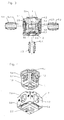
- FIG. 1 to 6 show a manifold and some tubular Distributors of a device not shown for the rest Interconnection of several hydraulic or pneumatic Components.
- the distributor shown is as a branch element trained, for example, in a manner not shown multiple solenoid valves can be connected.
- the distributor piece is constructed in two parts, it has an inner part 1, which, as shown in FIG. 4, can be inserted into an outer part 2. Both the outer part 2 and the inner part 1 are in their outer Forms essentially cuboid.
- the outer part 2 is open on the side pointing upwards in FIGS. 1 to 4, so that the inner part 1 can be inserted.
- the inner part 1 has through channels D1 and D2 and a third, in the Drawings not visible passage channel.
- inner connection openings are arranged, wherein the connection openings 1.1 and 1.2 through the passage D1 are connected while the connection opening 1.3 to the passage channel D2 and the connection opening 1.4 on the not shown Passage channel connects.
- the outer part 2 which is a rectangular External cross section and one adapted to the inner part 1 Has internal cross section, contributes coaxially in its outer walls the inner connection openings of the inner part 1 arranged outer Connection openings 2.1, 2.2, 2.3 and 2.4. Furthermore are in the side walls and the bottom wall of the outer part 2 pocket-like, with Guided insertion openings 2.5, 2.6, 2.7, 2.8 arranged, into which locking elements 4.1, 4.2, 4.3, 4.4 can be inserted are described in more detail below.
- plug-type connectors 3.1, 3.2, 3.3, 3.4 which through the outer connection openings in the outer part 2 into the inner connection openings of the inner part 1 are inserted can, as shown in Figs. 2 and 3.
- the plug-like Connectors are like sealing rings at their ends For example, 5.11, 5.21 and 5.31 provided by which a sealed Connection between the plug-like connector and the respective passage channel in the inner part 1 is reached becomes.
- locking elements can be designed as described in EP 0 982 520 A2 is.
- each of the Outer part 2 insertable locking elements one in the inserted Condition rotatable around the central axis of the connection opening Locking ring.
- a locking ring 4.41 which is radial carries inwardly extending locking elements and over an operating lever 4.42 led outwards by a predetermined one Angle of rotation from an assembly position into a locking position is rotatable.
- the plug-like connectors each have several radially outward as stop elements extending locking cams at predetermined angular intervals are arranged with spaces.
- the width of the gaps between the locking cams is at least so as large as the width of the locking segments on the locking ring 4.41 in the circumferential direction, and the width of the gaps between the locking segments is at least as large as the width of the locking cams 3.41 in the circumferential direction.
- the locking cams 3.41 At a Turn the locking ring 4.41 from the mounting position in the locking position, the locking cams 3.41 from engaging behind the locking segments of the locking ring 4.41, so that the connector falls out or pulls out 3.4 from the connection opening 2.4 is no longer possible. After swinging the locking ring 4.41 out of the Locking position in the mounting position can be the connector 3.4 are pulled out again. Except for the locking cams 3.41 the connector 3.4 still carries guide cams 3.42 that when plugging in between on the inner circumference of the connection opening 2.4 arranged guide ribs 2.41 engage and to serve axial guidance of the connecting piece.
- the locking elements and locking segments are analogous of the other connectors 3.1, 3.2, 3.3 and the locking rings 4.1, 4.2, 4-3 built. Other features these locking elements can the document cited above be removed.
- the inner part 1 has on its insertion a side protruding from the outer part 2, on the outer part 2 on the collar 1.5.
Abstract
Description
Die Erfindung betrifft eine Einrichtung zum Zusammenschalten mehrerer hydraulischer oder pneumatischer Komponenten, insbesondere mehrerer Elektromagnetventile in Serien- und/oder Parallelschaltung mit den Merkmalen aus dem Oberbegriff des Patentanspruchs 1.The invention relates to a device for interconnecting several hydraulic or pneumatic components, in particular several solenoid valves in series and / or parallel connection with the features from the preamble of claim 1.
Eine derartige Einrichtung ist beispielsweise in EP 0 982 520 A2 sowie in der in letzterem Dokument zitierten EP 0 715 112 A2 beschrieben.Such a device is for example in EP 0 982 520 A2 and in EP 0 715 112 A2 cited in the latter document.
Der Erfindung liegt die Aufgabe zugrunde, eine Einrichtung der oben angegebenen Art so auszugestalten, daß ihre Herstellung insbesondere bei der Formung aus Kunststoffmaterial erheblich vereinfacht wird. Insbesondere sollte erreicht werden, daß eine leichte Montage der Verriegelungselemente möglich ist, und zwar derart, daß die Verriegelungselemente möglichst nicht in Berühung mit dem die Einrichtung durchströmenden Medium kommen.The invention has for its object a device of the above Specify specified type so that their manufacture in particular considerably simplified when molding from plastic material becomes. In particular, it should be achieved that easy assembly the locking elements is possible, in such a way that the Locking elements if possible not in contact with the device flowing medium come.
Die Lösung dieser Aufgabe erfolgt erfindungsgemäß mit den Merkmalen aus dem kennzeichnenden Teil des Patentanspruchs 1. Vorteilhafte Weiterbildungen der Erfindung sind in den abhängigen Ansprüchen beschrieben.This object is achieved according to the invention with the features from the characterizing part of claim 1. Advantageous Further developments of the invention are in the dependent Described claims.
Der Grundgedanke der Erfindung besteht darin, das Verteilerstück zweiteilig aufzubauen mit einem quaderförmigen Innenteil, das von einem Außenteil umgeben und insbesondere in dieses Außenteil einsteckbar ist. Die Ausbildung ist derart, daß die steckerartigen Verbindungsstücke zur Verbindung der Verteilerstücke untereinander durch das Außenteil hindurch in das Innenteil eingesteckt werden, so daß das Außenteil mit dem Medium nicht in Berührung kommt. Die Verriegelungselemente können dann im Außenteil angeordnet werden, insbesondere in Führungen oder Taschen des Außenteils eingesteckt werden. Als besonders vorteilhaft hat es sich dabei erwiesen, wenn die Verriegelungselemente so aufgebaut sind, wie dies in EP 0 982 520 A2 beschrieben ist.The basic idea of the invention is the distributor to build in two parts with a cuboid inner part, which by surround an outer part and in particular in this outer part is insertable. The training is such that the plug-like Connectors for connecting the manifolds to each other inserted through the outer part into the inner part, so that the outer part does not come into contact with the medium. The Locking elements can then be arranged in the outer part, especially inserted in guides or pockets of the outer part become. It has proven to be particularly advantageous if the locking elements are constructed as shown in EP 0 982 520 A2.
Der zweiteilige Aufbau des Verteilerstücks bringt den Vorteil, daß bei einer Herstellung aus Kunststoffmaterial für die beiden Teile getrennte Formen vorgesehen werden können und die Formen zur Herstellung der beiden Teile sehr viel einfacher ausgestaltet sind und damit leichter hergestellt werden können. Weiterhin bietet die zweiteilige Ausführung die Möglichkeit, die beiden Teile aus unterschiedlichen Materialien herzustellen. Das Innenteil des Verteilerstücks kann als Ventil, insbesondere Elektromagnetventil, ausgebildet sein. In diesem Falle ist es vorteilhaft, wenn das Innenteil, welches in das Außenteil einsteckbar ist, an der beim Einstecken vom Außenteil abgewandten Seite eine Betätigungseinrichtung für das Ventil, insbesondere ein Magnetsystem für ein Elektromagnetventil, aufweist.The two-part construction of the distributor piece has the advantage that in a production of plastic material for the two parts separately Shapes can be provided and the shapes for Manufacture of the two parts are designed much easier and so that it can be manufactured more easily. Furthermore, the two-part offers Execution the possibility of the two parts from different To manufacture materials. The inner part of the manifold can be designed as a valve, in particular an electromagnetic valve his. In this case, it is advantageous if the inner part, which is plugged into the outer part on which when plugging in External part facing away from an actuator for Valve, in particular a magnet system for an electromagnetic valve, having.
Das Verteilerstück kann aber auch so ausgebildet sein, daß es lediglich mit geraden oder gekrümmten Durchtrittskanälen oder Abzweigungen versehen ist und zum Zusammenschalten von Ventilen oder anderen Vorrichtungen dient.The distributor can also be designed so that it only with straight or curved passage channels or Branches is provided and for interconnecting Valves or other devices.
Im folgenden wird anhand der beigefügten Zeichnungen ein Ausführungsbeispiel für eine Einrichtung nach der Erfindung näher erläutert.In the following an embodiment will be made with reference to the accompanying drawings for a device according to the invention explained.
In den Zeichnungen zeigen:
Die Fig. 1 bis 6 zeigen ein Verteilerstück sowie einige rohrförmige Verteilerstücke einer im übrigen nicht dargestellten Einrichtung zum Zusammenschalten mehrerer hydraulischer oder pneumatischer Komponenten. Das dargestellte Verteilerstück ist als Abzweigelement ausgebildet, an das in nicht eigens dargestellter Weise beispielsweise mehrere Elektromagnetventile angeschlossen werden können.1 to 6 show a manifold and some tubular Distributors of a device not shown for the rest Interconnection of several hydraulic or pneumatic Components. The distributor shown is as a branch element trained, for example, in a manner not shown multiple solenoid valves can be connected.
Das Verteilerstück ist zweiteilig aufgebaut, es besitzt ein Innenteil 1,
das, wie Fig. 4 zeigt, in ein Außenteil 2 eingesteckt werden kann.
Sowohl das Außenteil 2 als auch das Innenteil 1 sind in ihren äußeren
Formen im wesentlichen quaderförmig aufgebaut. Das Außenteil
2 ist an der in den Fig. 1 bis 4 nach oben weisenden Seite offen,
so daß das Innenteil 1 eingesteckt werden kann. Das Innenteil 1
besitzt Durchtrittskanäle D1 und D2 sowie einen dritten, in den
Zeichnungen nicht sichtbaren Durchtrittskanal. An den Außenflächen
des Innenteils 1 sind innere Anschlußöffnungen angeordnet, wobei
die Anschlußöffnungen 1.1 und 1.2 durch den Durchtrittskanal D1
verbunden sind, während die Anschlußöffnung 1.3 an den Durchtrittskanal
D2 und die Anschlußöffnung 1.4 an den nicht dargestellten
Durchtrittskanal anschließt. Das Außenteil 2, das einen rechteckigen
Außenquerschnitt und einen an das Innenteil 1 angepaßten
Innenquerschnitt besitzt, trägt in seinen Außenwänden koaxial zu
den inneren Anschlußöffnungen des Innenteils 1 angeordnete äußere
Anschlußöffnungen 2.1, 2.2, 2.3 und 2.4. Weiterhin sind in den Seitenwänden
und der Bodenwand des Außenteils 2 taschenartige, mit
Führungen versehene Einstecköffnungen 2.5, 2.6, 2.7, 2.8 angeordnet,
in welche Verriegelungselemente 4.1, 4.2, 4.3, 4.4 einsteckbar
sind, die weiter unten näher beschrieben werden.The distributor piece is constructed in two parts, it has an inner part 1,
which, as shown in FIG. 4, can be inserted into an
Zur Verbindung des aus dem Innenteil 1 und dem Außenteil 2 bestehenden,
zusammengesetzten Verteilerstücks mit einem anderen
Verteilerstück oder einem Ventil oder dergleichen dienen rohrförmige,
steckerartige Verbindungsstücke 3.1, 3.2, 3.3, 3.4, welche
durch die äußeren Anschlußöffnungen im Außenteil 2 hindurch in die
inneren Anschlußöffnungen des Innenteils 1 eingesteckt werden
können, wie dies in den Fig. 2 und 3 dargestellt ist. Die steckerartigen
Verbindungsstücke sind an ihren Enden mit Dichtungsringen wie
beispielsweise 5.11, 5.21 und 5.31 versehen, durch welche eine abgedichtete
Verbindung zwischen dem steckerartigen Verbindungsstück
und dem jeweiligen Durchtrittskanal im Innenteil 1 erreicht
wird.For connecting the inner part 1 and
Um ein Herausfallen oder Herausgleiten der Verbindungsstücke aus dem Verteilerstück zu verhindern, werden diese nach dem Einstecken durch Verriegelungselemente verriegelt. Diese Verriegelungselemente können so ausgebildet sein, wie dies in EP 0 982 520 A2 beschrieben ist.To prevent the connectors from falling out or sliding out to prevent the manifold, these will be plugged in locked by locking elements. These locking elements can be designed as described in EP 0 982 520 A2 is.
Im dargestellten Ausführungsbeispiel besitzt jedes der in das
Außenteil 2 einsteckbaren Verriegelungselemente einen im eingesteckten
Zustand um die Mittelachse der Anschlußöffnung drehbaren
Verriegelungsring. So besitzt beispielsweise das in Fig. 6 dargestellte
Verriegelungselement 4.4 einen Verriegelungsring 4.41, der sich radial
nach innen erstreckende Verriegelungselemente trägt und über
einen nach außen geführten Betätigungshebel 4.42 um einen vorgegebenen
Drehwinkel aus einer Montagestellung in eine Verriegelungsstellung
verdrehbar ist. Die steckerartigen Verbindungsstücke
besitzen als Anschlagelemente jeweils mehrere sich radial nach außen
erstreckende Verriegelungsnocken, die in vorgegebenen Winkelabständen
mit Zwischenräumen angeordnet sind. So besitzt beispielsweise
das in Fig. 6 dargestellte Verteilerstück 3.4 an jedem
seiner Enden vier Verriegelungsnocken 3.41. Die Weite der Zwischenräume
zwischen den Verriegelungsnocken ist mindestens so
groß wie die Breite der Verriegelungssegmente am Verriegelungsring
4.41 in Umfangsrichtung, und die Weite der Zwischenräume
zwischen den Verriegelungssegmenten ist mindestens so groß wie
die Breite der Verriegelungsnocken 3.41 in Umfangsrichtung. Auf
diese Weise wird erreicht, daß beim Einstecken des steckerartigen
Verbindungsstücks 3.4 in die buchsenartige Anschlußöffnung 2.4 in
der Montagestellung des Verriegelungsrings 4.41 die Verriegelungssegmente
zwischen den Verriegelungsnocken 3.41 hindurchtreten
und die Einstecktiefe so festgelegt ist, daß die Verriegelungsnocken
im voll eingesteckten Zustand in Einsteckrichtung gesehen unmittelbar
hinter der Bahn der Verriegelungssegmente liegen. Bei einer
Verdrehung des Verriegelungsrings 4.41 aus der Montagestellung in
die Verriegelungsstellung werden die Verriegelungsnocken 3.41 von
den Verriegelungssegmenten des Verriegelungsrings 4.41 hintergriffen,
so daß ein Herausfallen oder Herausziehen des Verbindungsstücks
3.4 aus der Anschlußöffnung 2.4 nicht mehr möglich ist.
Nach dem Zurückschwenken des Verriegelungsrings 4.41 aus der
Verriegelungsstellung in die Montagestellung kann das Verbindungsstück
3.4 wieder herausgezogen werden. Außer den Verriegelungsnocken
3.41 trägt das Verbindungsstück 3.4 noch Führungsnocken
3.42, die beim Einstecken zwischen am Innenumfang der Anschlußöffnung
2.4 angeordnete Führungsrippen 2.41 eingreifen und zur
axialen Führung des Verbindungsstücks dienen.In the illustrated embodiment, each of the
In analoger Weise sind die Verriegelungselemente und Verriegelungssegmente der anderen Verbindungsstücke 3.1, 3.2, 3.3 und der Verriegelungsringe 4.1, 4.2, 4-3 aufgebaut. Weitere Merkmale dieser Verriegelungselemente können dem oben zitierten Dokument entnommen werden.The locking elements and locking segments are analogous of the other connectors 3.1, 3.2, 3.3 and the locking rings 4.1, 4.2, 4-3 built. Other features these locking elements can the document cited above be removed.
Um einen festen Sitz des Innenteils 1 im Außenteil 2 nach dem Einstecken
zu erreichen, weist das Innenteil 1 an seiner beim Einstecken
vom Außenteil 2 abgewandten Seite einen überstehenden, sich auf
das Außenteil 2 aufsetzenden Kragen 1.5 auf.To ensure a firm fit of the inner part 1 in the
Claims (7)
Applications Claiming Priority (2)
| Application Number | Priority Date | Filing Date | Title |
|---|---|---|---|
| DE2001163785 DE10163785A1 (en) | 2001-12-22 | 2001-12-22 | Device for interconnecting several hydraulic or pneumatic components, in particular several solenoid valves |
| DE10163785 | 2001-12-22 |
Publications (3)
| Publication Number | Publication Date |
|---|---|
| EP1321698A2 true EP1321698A2 (en) | 2003-06-25 |
| EP1321698A3 EP1321698A3 (en) | 2003-09-03 |
| EP1321698B1 EP1321698B1 (en) | 2006-08-02 |
Family
ID=7710742
Family Applications (1)
| Application Number | Title | Priority Date | Filing Date |
|---|---|---|---|
| EP20020027808 Expired - Lifetime EP1321698B1 (en) | 2001-12-22 | 2002-12-12 | Device to interconnect more hydraulic or pneumatic components in particular electromagnetic valves |
Country Status (3)
| Country | Link |
|---|---|
| EP (1) | EP1321698B1 (en) |
| DE (2) | DE10163785A1 (en) |
| DK (1) | DK1321698T3 (en) |
Cited By (5)
| Publication number | Priority date | Publication date | Assignee | Title |
|---|---|---|---|---|
| WO2006105104A1 (en) * | 2005-03-29 | 2006-10-05 | Norgren, Inc. | A valve for an expandable gas or fluid distribution system |
| WO2006097892A3 (en) * | 2005-03-15 | 2007-02-15 | Ferrero Rubinetterie S R L | Manifold for fluids |
| WO2008016352A1 (en) * | 2006-08-02 | 2008-02-07 | Norgren, Inc. | A modular rotary connection system with a separate locking piece |
| WO2009101076A1 (en) * | 2008-02-15 | 2009-08-20 | Voss Automotive Gmbh | Multiple plug coupling for media lines |
| EP2886926A1 (en) * | 2013-12-20 | 2015-06-24 | AGCO International GmbH | Hydraulic coupling seal |
Families Citing this family (1)
| Publication number | Priority date | Publication date | Assignee | Title |
|---|---|---|---|---|
| CN106870856B (en) * | 2017-03-29 | 2021-06-22 | 同济大学 | Cube type quasi-equal flow rate hydraulic pipeline series multi-way connecting block capable of being fixedly connected |
Citations (2)
| Publication number | Priority date | Publication date | Assignee | Title |
|---|---|---|---|---|
| EP0715112A2 (en) | 1994-12-03 | 1996-06-05 | A. und K. MÜLLER GmbH & Co. KG | Device for simultaneous connection of electrovalves |
| EP0982520A2 (en) | 1998-08-20 | 2000-03-01 | A. und K. Müller GmbH & Co. KG | Device for connecting together hydraulic or pneumatic components, particularly solenoid valves |
Family Cites Families (3)
| Publication number | Priority date | Publication date | Assignee | Title |
|---|---|---|---|---|
| FR2581157B1 (en) * | 1985-04-29 | 1987-05-29 | Legris Sa | IMPROVEMENT IN THE DISTRIBUTION OF FLUIDS IN MULTIPLE CONDUITS. |
| DE9402093U1 (en) * | 1994-02-08 | 1994-03-31 | Buerkert Werke Gmbh & Co | Modular valve and distributor system for flowing media |
| WO2001071236A1 (en) * | 2000-03-20 | 2001-09-27 | Giacomini S.P.A. | Modular manifold for heating and sanitary systems |
-
2001
- 2001-12-22 DE DE2001163785 patent/DE10163785A1/en not_active Withdrawn
-
2002
- 2002-12-12 DE DE50207711T patent/DE50207711D1/en not_active Expired - Lifetime
- 2002-12-12 DK DK02027808T patent/DK1321698T3/en active
- 2002-12-12 EP EP20020027808 patent/EP1321698B1/en not_active Expired - Lifetime
Patent Citations (2)
| Publication number | Priority date | Publication date | Assignee | Title |
|---|---|---|---|---|
| EP0715112A2 (en) | 1994-12-03 | 1996-06-05 | A. und K. MÜLLER GmbH & Co. KG | Device for simultaneous connection of electrovalves |
| EP0982520A2 (en) | 1998-08-20 | 2000-03-01 | A. und K. Müller GmbH & Co. KG | Device for connecting together hydraulic or pneumatic components, particularly solenoid valves |
Cited By (10)
| Publication number | Priority date | Publication date | Assignee | Title |
|---|---|---|---|---|
| WO2006097892A3 (en) * | 2005-03-15 | 2007-02-15 | Ferrero Rubinetterie S R L | Manifold for fluids |
| WO2006105104A1 (en) * | 2005-03-29 | 2006-10-05 | Norgren, Inc. | A valve for an expandable gas or fluid distribution system |
| EP2110588A2 (en) * | 2005-03-29 | 2009-10-21 | Norgren, Inc. | A valve for an expandable gas or fluid distribution system |
| EP2110588A3 (en) * | 2005-03-29 | 2010-01-20 | Norgren, Inc. | A valve for an expandable gas or fluid distribution system |
| EP2103854A3 (en) * | 2005-03-29 | 2010-01-20 | Norgren, Inc. | A valve for an expandable gas or fluid distribution system |
| WO2008016352A1 (en) * | 2006-08-02 | 2008-02-07 | Norgren, Inc. | A modular rotary connection system with a separate locking piece |
| US8141915B2 (en) | 2006-08-02 | 2012-03-27 | Norgren, Inc. | Modular rotary connection system with a separate locking piece |
| CN101501344B (en) * | 2006-08-02 | 2012-07-04 | 诺格伦公司 | A modular rotary connection system with a separate locking piece |
| WO2009101076A1 (en) * | 2008-02-15 | 2009-08-20 | Voss Automotive Gmbh | Multiple plug coupling for media lines |
| EP2886926A1 (en) * | 2013-12-20 | 2015-06-24 | AGCO International GmbH | Hydraulic coupling seal |
Also Published As
| Publication number | Publication date |
|---|---|
| EP1321698A3 (en) | 2003-09-03 |
| DE50207711D1 (en) | 2006-09-14 |
| DK1321698T3 (en) | 2006-11-27 |
| EP1321698B1 (en) | 2006-08-02 |
| DE10163785A1 (en) | 2003-07-03 |
Similar Documents
| Publication | Publication Date | Title |
|---|---|---|
| DE1425580A1 (en) | Sealing device which can be introduced into a bore of a housing and produces a seal between the housing and a part that is movable in the bore | |
| DE4443081A1 (en) | Device for interconnecting several solenoid valves | |
| WO2007101525A1 (en) | Multicoupling device | |
| DE102020202520A1 (en) | Distribution valve and cooling system | |
| DE2839774C2 (en) | ||
| DE19837767C2 (en) | Device for connecting hydraulic or pneumatic components, in particular electromagnetic valves, to one another | |
| DE102021000262A9 (en) | mass flow control device | |
| EP1853839B1 (en) | Kit and series of multiway valves | |
| EP1321698B1 (en) | Device to interconnect more hydraulic or pneumatic components in particular electromagnetic valves | |
| DE19616973C2 (en) | More directional spool valve | |
| DE3810385C2 (en) | ||
| EP3565991A1 (en) | Valve arrangement | |
| EP0857901B1 (en) | Valve | |
| DE202004011202U1 (en) | Modular seal for pipes passing through walls comprises flexible ring which is compressed between two locking rings so that it expands radially and is made up of three coaxial sections of different diameter | |
| EP1614944A1 (en) | Multiple way valve or distribution valve | |
| DE102015209025A1 (en) | Ball valve and method for its production | |
| EP3940272B1 (en) | Shut-off valve in particular for use in sanitary facilities | |
| EP3388722A1 (en) | Fluid valve comprising a first body and a second body | |
| EP1469245B1 (en) | Plug-in coupling | |
| AT395347B (en) | Screw-in valve | |
| EP1517072B1 (en) | Valve | |
| DE102008062873A1 (en) | Valve housing body, particularly for seat valve, has assembly channel for control element for closing element, which cooperates with valve seat in housing inner area | |
| DE102023117369A1 (en) | Ball valve of a refrigerant valve device for an air conditioning system | |
| DE102019128468A1 (en) | Flow system for fluids with a switching device | |
| EP3745008A1 (en) | 2 / 2 or 3/3-way valve and method of manufacturing the same |
Legal Events
| Date | Code | Title | Description |
|---|---|---|---|
| PUAI | Public reference made under article 153(3) epc to a published international application that has entered the european phase |
Free format text: ORIGINAL CODE: 0009012 |
|
| AK | Designated contracting states |
Designated state(s): AT BE BG CH CY CZ DE DK EE ES FI FR GB GR IE IT LI LU MC NL PT SE SI SK TR |
|
| AX | Request for extension of the european patent |
Extension state: AL LT LV MK RO |
|
| PUAL | Search report despatched |
Free format text: ORIGINAL CODE: 0009013 |
|
| AK | Designated contracting states |
Kind code of ref document: A3 Designated state(s): AT BE BG CH CY CZ DE DK EE ES FI FR GB GR IE IT LI LU MC NL PT SE SI SK TR |
|
| AX | Request for extension of the european patent |
Extension state: AL LT LV MK RO |
|
| RIC1 | Information provided on ipc code assigned before grant |
Ipc: 7F 15B 13/00 B Ipc: 7F 16K 31/06 B Ipc: 7F 16K 27/00 A |
|
| 17P | Request for examination filed |
Effective date: 20040115 |
|
| AKX | Designation fees paid |
Designated state(s): CH CZ DE DK FR GB IT LI NL |
|
| GRAP | Despatch of communication of intention to grant a patent |
Free format text: ORIGINAL CODE: EPIDOSNIGR1 |
|
| GRAS | Grant fee paid |
Free format text: ORIGINAL CODE: EPIDOSNIGR3 |
|
| GRAA | (expected) grant |
Free format text: ORIGINAL CODE: 0009210 |
|
| AK | Designated contracting states |
Kind code of ref document: B1 Designated state(s): CH CZ DE DK FR GB IT LI NL |
|
| PG25 | Lapsed in a contracting state [announced via postgrant information from national office to epo] |
Ref country code: CZ Free format text: LAPSE BECAUSE OF FAILURE TO SUBMIT A TRANSLATION OF THE DESCRIPTION OR TO PAY THE FEE WITHIN THE PRESCRIBED TIME-LIMIT Effective date: 20060802 |
|
| REG | Reference to a national code |
Ref country code: GB Ref legal event code: FG4D Free format text: NOT ENGLISH |
|
| REG | Reference to a national code |
Ref country code: CH Ref legal event code: EP |
|
| REF | Corresponds to: |
Ref document number: 50207711 Country of ref document: DE Date of ref document: 20060914 Kind code of ref document: P |
|
| REG | Reference to a national code |
Ref country code: CH Ref legal event code: NV Representative=s name: A. BRAUN, BRAUN, HERITIER, ESCHMANN AG PATENTANWAE |
|
| GBT | Gb: translation of ep patent filed (gb section 77(6)(a)/1977) |
Effective date: 20060923 |
|
| REG | Reference to a national code |
Ref country code: DK Ref legal event code: T3 |
|
| ET | Fr: translation filed | ||
| PLBE | No opposition filed within time limit |
Free format text: ORIGINAL CODE: 0009261 |
|
| STAA | Information on the status of an ep patent application or granted ep patent |
Free format text: STATUS: NO OPPOSITION FILED WITHIN TIME LIMIT |
|
| 26N | No opposition filed |
Effective date: 20070503 |
|
| PGFP | Annual fee paid to national office [announced via postgrant information from national office to epo] |
Ref country code: DK Payment date: 20071227 Year of fee payment: 6 Ref country code: NL Payment date: 20071227 Year of fee payment: 6 |
|
| PGFP | Annual fee paid to national office [announced via postgrant information from national office to epo] |
Ref country code: IT Payment date: 20071220 Year of fee payment: 6 |
|
| REG | Reference to a national code |
Ref country code: CH Ref legal event code: PFA Owner name: A. UND K. MUELLER GMBH & CO. KG Free format text: A. UND K. MUELLER GMBH & CO. KG#DRESDENER STRASSE 162#40595 DUESSELDORF (DE) -TRANSFER TO- A. UND K. MUELLER GMBH & CO. KG#DRESDENER STRASSE 162#40595 DUESSELDORF (DE) |
|
| REG | Reference to a national code |
Ref country code: DK Ref legal event code: EBP |
|
| NLV4 | Nl: lapsed or anulled due to non-payment of the annual fee |
Effective date: 20090701 |
|
| PG25 | Lapsed in a contracting state [announced via postgrant information from national office to epo] |
Ref country code: NL Free format text: LAPSE BECAUSE OF NON-PAYMENT OF DUE FEES Effective date: 20090701 |
|
| PG25 | Lapsed in a contracting state [announced via postgrant information from national office to epo] |
Ref country code: DK Free format text: LAPSE BECAUSE OF NON-PAYMENT OF DUE FEES Effective date: 20090105 |
|
| PGFP | Annual fee paid to national office [announced via postgrant information from national office to epo] |
Ref country code: FR Payment date: 20091209 Year of fee payment: 8 Ref country code: GB Payment date: 20091230 Year of fee payment: 8 |
|
| GBPC | Gb: european patent ceased through non-payment of renewal fee |
Effective date: 20101212 |
|
| REG | Reference to a national code |
Ref country code: FR Ref legal event code: ST Effective date: 20110831 |
|
| PG25 | Lapsed in a contracting state [announced via postgrant information from national office to epo] |
Ref country code: FR Free format text: LAPSE BECAUSE OF NON-PAYMENT OF DUE FEES Effective date: 20110103 |
|
| PG25 | Lapsed in a contracting state [announced via postgrant information from national office to epo] |
Ref country code: GB Free format text: LAPSE BECAUSE OF NON-PAYMENT OF DUE FEES Effective date: 20101212 |
|
| PG25 | Lapsed in a contracting state [announced via postgrant information from national office to epo] |
Ref country code: IT Free format text: LAPSE BECAUSE OF NON-PAYMENT OF DUE FEES Effective date: 20081212 |
|
| REG | Reference to a national code |
Ref country code: CH Ref legal event code: PCAR Free format text: NEW ADDRESS: HOLBEINSTRASSE 36-38, 4051 BASEL (CH) |
|
| PGFP | Annual fee paid to national office [announced via postgrant information from national office to epo] |
Ref country code: CH Payment date: 20151222 Year of fee payment: 14 |
|
| REG | Reference to a national code |
Ref country code: CH Ref legal event code: PL |
|
| PG25 | Lapsed in a contracting state [announced via postgrant information from national office to epo] |
Ref country code: CH Free format text: LAPSE BECAUSE OF NON-PAYMENT OF DUE FEES Effective date: 20161231 Ref country code: LI Free format text: LAPSE BECAUSE OF NON-PAYMENT OF DUE FEES Effective date: 20161231 |
|
| PGFP | Annual fee paid to national office [announced via postgrant information from national office to epo] |
Ref country code: DE Payment date: 20211231 Year of fee payment: 20 |
|
| REG | Reference to a national code |
Ref country code: DE Ref legal event code: R071 Ref document number: 50207711 Country of ref document: DE |