EP0333045A1 - Vacuum sewage conveying system - Google Patents
Vacuum sewage conveying system Download PDFInfo
- Publication number
- EP0333045A1 EP0333045A1 EP89104226A EP89104226A EP0333045A1 EP 0333045 A1 EP0333045 A1 EP 0333045A1 EP 89104226 A EP89104226 A EP 89104226A EP 89104226 A EP89104226 A EP 89104226A EP 0333045 A1 EP0333045 A1 EP 0333045A1
- Authority
- EP
- European Patent Office
- Prior art keywords
- suction
- pump
- tank
- discharge
- liquid ring
- Prior art date
- Legal status (The legal status is an assumption and is not a legal conclusion. Google has not performed a legal analysis and makes no representation as to the accuracy of the status listed.)
- Granted
Links
- 239000010865 sewage Substances 0.000 title abstract 4
- 239000007788 liquid Substances 0.000 claims abstract description 50
- XLYOFNOQVPJJNP-UHFFFAOYSA-N water Substances O XLYOFNOQVPJJNP-UHFFFAOYSA-N 0.000 claims abstract description 38
- 239000002351 wastewater Substances 0.000 claims description 42
- 239000000463 material Substances 0.000 claims description 10
- 238000005273 aeration Methods 0.000 claims description 8
- 238000000926 separation method Methods 0.000 claims description 7
- 230000002093 peripheral effect Effects 0.000 claims description 4
- 238000007599 discharging Methods 0.000 claims description 3
- 238000005086 pumping Methods 0.000 claims description 3
- 239000012530 fluid Substances 0.000 claims description 2
- 239000005416 organic matter Substances 0.000 claims description 2
- 239000008400 supply water Substances 0.000 claims description 2
- 238000011010 flushing procedure Methods 0.000 abstract description 2
- 239000013505 freshwater Substances 0.000 abstract 1
- 230000007246 mechanism Effects 0.000 abstract 1
- 239000007789 gas Substances 0.000 description 9
- 238000009434 installation Methods 0.000 description 9
- 238000000034 method Methods 0.000 description 9
- 230000005484 gravity Effects 0.000 description 4
- 208000031968 Cadaver Diseases 0.000 description 2
- 230000015556 catabolic process Effects 0.000 description 2
- 230000006835 compression Effects 0.000 description 2
- 238000007906 compression Methods 0.000 description 2
- 238000006731 degradation reaction Methods 0.000 description 2
- 239000002245 particle Substances 0.000 description 2
- 239000011343 solid material Substances 0.000 description 2
- 238000011144 upstream manufacturing Methods 0.000 description 2
- 238000009423 ventilation Methods 0.000 description 2
- 239000003570 air Substances 0.000 description 1
- 230000005587 bubbling Effects 0.000 description 1
- 238000004891 communication Methods 0.000 description 1
- 238000001816 cooling Methods 0.000 description 1
- 239000000428 dust Substances 0.000 description 1
- 230000000694 effects Effects 0.000 description 1
- 235000021183 entrée Nutrition 0.000 description 1
- 238000010438 heat treatment Methods 0.000 description 1
- 238000007689 inspection Methods 0.000 description 1
- 230000003134 recirculating effect Effects 0.000 description 1
- 230000001105 regulatory effect Effects 0.000 description 1
- 239000007779 soft material Substances 0.000 description 1
- 239000007787 solid Substances 0.000 description 1
- 239000011800 void material Substances 0.000 description 1
- 239000003643 water by type Substances 0.000 description 1
Images


Classifications
-
- F—MECHANICAL ENGINEERING; LIGHTING; HEATING; WEAPONS; BLASTING
- F04—POSITIVE - DISPLACEMENT MACHINES FOR LIQUIDS; PUMPS FOR LIQUIDS OR ELASTIC FLUIDS
- F04C—ROTARY-PISTON, OR OSCILLATING-PISTON, POSITIVE-DISPLACEMENT MACHINES FOR LIQUIDS; ROTARY-PISTON, OR OSCILLATING-PISTON, POSITIVE-DISPLACEMENT PUMPS
- F04C19/00—Rotary-piston pumps with fluid ring or the like, specially adapted for elastic fluids
- F04C19/001—General arrangements, plants, flowsheets
-
- E—FIXED CONSTRUCTIONS
- E03—WATER SUPPLY; SEWERAGE
- E03F—SEWERS; CESSPOOLS
- E03F1/00—Methods, systems, or installations for draining-off sewage or storm water
- E03F1/006—Pneumatic sewage disposal systems; accessories specially adapted therefore
Definitions
- Waste water evacuation systems have been known for a long time. Such waters often contain poorly resistant materials. They come in particular from water closet bowls. They circulate in the vacuum evacuation conduits in the form of bundles which occupy the entire section of the conduit and which are therefore called plugs. These plugs are followed by air masses which ensure their propulsion.
- vacuum evacuation has three essential advantages: - the diameters of the conduits required for vacuum evacuation are much smaller than the diameters necessary for gravity evacuation, - unlike gravity evacuation, vacuum evacuation works regardless of the slope of the conduits. In particular, it allows the flow to go up to a maximum height corresponding to the value of the depression expressed in meters of water column, - the evacuation of water from a closet requires only a small volume of flushing: less than 1.5 liters of water, compared to 6 to 9 liters for gravity drainage systems.
- a first known technique consists in collecting the waste water in a tank which is put under vacuum by means of a vacuum pump. The function of this pump is only to create and maintain a vacuum in the installation. So it only sucks air. To be able to drain the tank without interrupting the operation of the installation, another pump must be able to suck up the materials under vacuum, or provide sophisticated airlock systems. Furthermore, the wastewater being stored under vacuum, the aerobic degradation of the materials does not take place.
- a second technique is known from French patent n ° 82 04710. It consists of completing the installation with vacuum pump by a barometric column which allows to transfer wastewater continuously from the vacuum network to a collector at atmospheric pressure.
- the storage tank is no longer essential.
- the major drawback of this technique is that it requires a significant height (5 to 10 m) between the collector and the low point of the vacuum network.
- a third known technique is described in French patent No. 2,308,742 and its American correspondent No. 4,034,421. According to this technique, a storage tank is used at atmospheric pressure. A circulation pump sucks the wastewater stored in this tank, and discharges it under pressure into an ejector, the diverging line of which returns it to the tank. The neck of the ejector is connected to the evacuation network in which it maintains the vacuum. Wastewater, air and materials are thus transferred from the vacuum network to the tank via the ejector.
- This technique has the advantage of leaving the storage tank at atmospheric pressure without major complication of the installation.
- a fourth known technique consists in using a vacuum pump with an Archimedes screw to create and maintain the vacuum in a tank connected to the wastewater collection network.
- a special screw pump capable of sucking liquids and gases has been developed for this application. This pump is not, however, capable of passing solids. The tank must therefore be equipped to sort the materials and grind them. Installation then becomes much more complex.
- the object of the present invention is in particular to provide a simple system for evacuating waste water under vacuum. It also aims to make this system robust, energy efficient and directly connectable, with or without storage tank, to a manifold at atmospheric pressure, without barometric column height constraints.
- a system according to the invention comprises the following elements which are common, at least as regards some of their purposes for this system and for a known system produced according to the third known technique mentioned above: a tubular collector for receiving said wastewater in the form of successive plugs, as well as air masses consecutive to these plugs and coming from the atmosphere, - and circulation, suction and discharge means connected to this manifold to suck up these plugs and these consecutive air masses by lowering the air pressure in said manifold to a suction pressure below atmospheric pressure, and for discharging said wastewater under a discharge pressure greater than said suction pressure and sufficient to allow their discharge.
- said circulation, suction and discharge means comprise in particular said circulation pump and said ejector, the latter for constituting suction and discharge means.
- the system according to the invention is characterized in that said suction and discharge circulation means comprise - a liquid ring pump provided with a suction passage connected to said collector, a discharge passage for the evacuation of said waste water, and a water supply passage for receiving a minority flow of supply water suitable for forming and / or maintaining a liquid ring in this pump, - And water supply means for supplying said feed water.
- said means of circulation, suction and discharge also comprise a reservoir receiving and temporarily containing said waste water under a storage pressure greater than said suction pressure.
- said reservoir is connected to said delivery passage of said liquid ring pump.
- a supply pipe connects a lower part of said tank to said suction passage of said liquid ring pump so as to suck up a minority flow of waste water from this tank to maintain said liquid ring, said water supply means supplying clear water and being controllable from so as to be able to stop supplying this clear water when this ring can be maintained by this waste water.
- the system further comprises valves and piping to allow, after a period of storage of said wastewater in said tank, which then constitutes a storage tank, to empty this tank under the action of suction and discharge of said pump with liquid ring.
- Said valves and pipes for emptying said storage tank comprise an air introduction valve which, when open, communicates said suction passage of said liquid ring pump with the atmosphere, - a separation valve which, when closed, eliminates the connection of this suction passage to said manifold, - And a drain pipe connecting a lower part of said storage tank to an evacuation zone so that, during a storage period during which this air introduction valve is closed and this separation valve open, this pump sucks said plugs and said consecutive air masses and discharges said waste water into said tank to store this waste water there, and so that, during a draining period during which this air introduction valve is open and this valve closed separation, this same pump draws an air flow from the atmosphere and discharges this air flow into said storage tank under a drain pressure which constitutes said discharge pressure and which is higher than the
- - Said storage tank is provided with an aeration valve which is located in the upper part and which is closed during said emptying period, and a drain valve which is located on said emptying pipe and which is open for this emptying period.
- - Said collector is connected to said suction passage of said liquid ring pump by means of a heavy particle trap.
- said tank is a storage tank for storing said waste water during said aeration time
- said delivery passage communicates with this tank by means of a delivery pipe opening out at the bottom of this tank, so that the air discharged by this pump rises in the form of bubbles through the thickness of the waste water stored in this tank -
- said liquid ring pump comprises - a pump body having a generally cylindrical peripheral wall around a body axis, - a rotor provided with blades, having a rotor axis and rotating in this body around this axis, the latter being offset relative to said body axis, - a motor to drive this rotor, a distributor constituting a wall in contact with the interior space of said pump body, - a suction light and a discharge light pierced in this distributor, - And a feed passage allowing water to be introduced into said body so that the water thus introduced constitutes a liquid ring driven in rotation by said blades of the rotor and pressed by centrifugal
- said suction light is sufficiently wide to contain a circle with a diameter of approximately 40 mm, so as to facilitate the suction of weak materials which can form part of said plugs.
- said liquid ring pump is further provided with tubular suction and delivery passages connected respectively to said suction and delivery ports and each having an axis.
- said axis of said suction passage and preferably that of said delivery passage are substantially parallel to said body and rotor axes and their extensions pass substantially through said suction and discharge ports, respectively.
- a liquid ring pump known for this use and shown in fig.1 comprises a rotor 11 provided with blades 11A and driven by an electric motor 10. This rotor rotates in a pump body 12 around a axis 11B parallel to the axis 12A of this body.
- the gas to be pumped enters through a suction flange 13 of a flange 14. It then passes into the pump body through a suction port 15 of a distributor 16 (see fig.3).
- the compressed gas is finally discharged by a discharge port 17 from the distributor and discharged by a discharge flange from the flange.
- a liquid ring 92 (see fig. 2) consists of water which has been introduced in suitable volume into the body 12 and driven in rotation by the rotor 11. It is pressed by centrifugal force against the cylindrical wall of this body and leaves a free axial volume for gas suction and compression. It constitutes a gas seal between the rotor blades and the wall of the pump body. Two successive blades and the liquid ring delimit a rotating chamber, the volume of which is large when it passes opposite the suction light 15 and small opposite the discharge light 17.
- FIG. 5 shows a first system in which the liquid ring pump is connected to a vacuum water collection network for wastewater.
- This network is shown schematically by a collector 42 to which is connected a water closet bowl provided with a flush and a vacuum-tight discharge valve. This flush and this valve are of known types and are not shown.
- the suction flange 33 is connected to the collection network.
- the discharge flange 34 is connected via the pipe 41 directly to the discharge pipe or sewer 44 which is at atmospheric pressure.
- the operation of the liquid ring pump requires a low flow water supply, intended to maintain the volume of the liquid ring and to ensure cooling. This supply reaches the supply port 19 of the pump by means of the conduit 45, the flow rate being regulated by the valve 46.
- the liquid ring pump ensures the transfer of gases, water and solid materials from the vacuum network to the sewer 44 at atmospheric pressure, as well as the grinding of these solid materials.
- a trap is placed upstream of the liquid ring pump to retain very heavy particles, such as for example metallic objects, which could have been introduced, by accident or maliciously, into the wastewater collection system which could damage the liquid ring pump.
- This trap can be constituted by a simple box 51 through which the wastewater transits, the inlet / outlet orifices 52 and 53 being placed at the top of the box so that heavy objects fall to the bottom of the box and fail at the pump.
- the box can be emptied periodically by means of an inspection hatch 54.
- a non-return valve 55 capable, by via a relay 57, to start the pump on a high pressure threshold and to stop it on a low pressure threshold.
- a vacuum switch 56 capable, by via a relay 57, to start the pump on a high pressure threshold and to stop it on a low pressure threshold.
- a drawback of the first system which has just been described according to the invention is the need to supply the liquid ring with clear water, which penalizes the water consumption of the entire installation.
- a storage tank 61 as indicated in FIG. 6.
- This tank is provided with 'a ventilation chimney 62 and a drain pipe 63 closed by a valve 64.
- the tank is emptied either periodically or continuously, by any means not described here, without the level falling below a minimum level located above the supply nozzle of a pipe 65 connecting the base of the tank to the suction pipe 66 of the liquid ring pump.
- the liquid ring can be supplied by recirculating part of the wastewater, the flow in the conduit 65 being effected without an auxiliary pump, under the effect of the vacuum created by the liquid ring pump.
- a supply of clear water 45 is however necessary in the start-up phase of the pump. This supply is then cut by the valve 46.
- FIG. 6 Another preferred arrangement also shown in FIG. 6 consists in extending the discharge line 71 of the liquid ring pump to the bottom of the tank.
- the air discharged by the pump escapes from the discharge pipe in the form of bubbles. This bubbling is conducive to aerobic degradation of the materials contained in the tank.
- the liquid ring pump is also used for emptying the storage tank. More particularly, here a temporary use is made of a liquid ring pump which is known in itself and according to which such a pump can operate as an air compressor.
- a separation valve 81 through which the storage tank is connected to the vacuum network and an air introduction valve 82 is opened which allows communication with the atmosphere.
- the pump then sucks in air at atmospheric pressure which it compresses by discharging it into the tank.
- a valve 83 located on the tank ventilation chimney. If a tank drain valve 84 is then opened, it results in a pressure drain of the latter. It is thus possible to discharge the waste water into a drain pipe 86 to a collecting duct 88 located higher than the tank.
Abstract
Description
Des systèmes d'évacuation sous vide d'eaux usées sont connus depuis longtemps. De telles eaux comportent souvent des matières peu résistantes. Elles proviennent notamment de cuvettes de water-closet. Elles circulent dans les conduits d'évacuation sous vide sous la forme des paquets qui occupent toute la section du conduit et qui sont pour cela appelés bouchons. Ces bouchons sont suivis par des masses d'air qui assurent leur propulsion.Waste water evacuation systems have been known for a long time. Such waters often contain poorly resistant materials. They come in particular from water closet bowls. They circulate in the vacuum evacuation conduits in the form of bundles which occupy the entire section of the conduit and which are therefore called plugs. These plugs are followed by air masses which ensure their propulsion.
Par rapport à une évacuation gravitaire, l'évacuation sous vide présente trois avantages essentiels :
- les diamètres des conduits requis pour l'évacuation sous vide sont nettement inférieurs aux diamètres nécessaires pour l'évacuation gravitaire,
- au contraire de l'évacuation gravitaire, l'évacuation sous vide fonctionne quelle que soit la pente des conduits. Elle permet notamment de faire remonter l'écoulement sur une hauteur maximale correspondant à la valeur de la dépression exprimée en mètres de colonne d'eau,
- l'évacuation des eaux de water-closet ne requiert qu'un faible volume de chasse : moins de 1,5 litre d'eau, contre 6 à 9 litres pour les systèmes à évacuation gravitaire.Compared to gravity evacuation, vacuum evacuation has three essential advantages:
- the diameters of the conduits required for vacuum evacuation are much smaller than the diameters necessary for gravity evacuation,
- unlike gravity evacuation, vacuum evacuation works regardless of the slope of the conduits. In particular, it allows the flow to go up to a maximum height corresponding to the value of the depression expressed in meters of water column,
- the evacuation of water from a closet requires only a small volume of flushing: less than 1.5 liters of water, compared to 6 to 9 liters for gravity drainage systems.
Ces avantages sont particulièrement intéressants pour l'évacuation d'eaux de water-closets dans des navires de surface ou sous-marins.These advantages are particularly advantageous for the evacuation of water from water closets in surface or submarine ships.
Différentes techniques sont connues pour générer le vide :
- Une première technique connue consiste à recueillir les eaux usées dans un réservoir qui est mis sous vide au moyen d'une pompe à vide. Cette pompe n'a pour fonction que de créer et maintenir le vide dans l'installation. Elle n'aspire donc que de l'air. Pour pouvoir effectuer la vidange du réservoir sans interrompre le fonctionnement de l'installation, il faut disposer d'une autre pompe pouvant aspirer les matières sous vides, ou prévoir des systèmes de sas sophistiqués. Par ailleurs les eaux usées étant stockées sous vide, la dégradation aérobie des matières ne s'effectue pas.
- Pour pallier ces inconvénients, une seconde technique est connue par le brevet français n° 82 04710 . Elle consiste à compléter l'installation avec pompe à vide par une colonne barométrique qui permet de transférer les eaux usées en continu du réseau sous vide vers un collecteur à la pression atmosphérique. Le réservoir de stockage n'est alors plus indispensable. L'inconvénient majeur de cette technique est de nécessiter une hauteur importante (de 5 à 10 m) entre le collecteur et le point bas du réseau sous vide.
- Une troisième technique connue est décrite dans le brevet français n° 2 308 742 et son correspondant américain n° 4 034 421. Suivant cette technique on utilise un réservoir de stockage à la pression atmosphérique. Une pompe de circulation aspire les eaux usées stockées dans ce réservoir, et les refoule sous pression dans un éjecteur dont le divergent les restitue au réservoir. Le col de l'éjecteur est raccordé au réseau d'évacuation dans lequel il maintient le vide. Les eaux usées, l'air et les matières sont ainsi transférés du réseau sous vide au réservoir par l'intermédiaire de l'éjecteur. Cette technique présente l'intérêt de laisser le réservoir de stockage à la pression atmosphérique sans complication majeure de l'installation. Elle présente cependant l'inconvénient propre aux éjecteurs qui est un mauvais rendement, ce qui traduit par une sur-puissance de la pompe de circulation, ou par la multiplication des groupes éjecteur/pompe.
- Enfin, une quatrième technique connue consiste à employer une pompe à vide à vis d'Archimède pour créer et maintenir le vide dans un réservoir connecté au réseau de collecte des eaux usées. Une pompe à vis spéciale capable d'aspirer des liquides et des gaz a été développée pour cette application. Cette pompe n'est cependant pas capable de faire transiter les matières solides. Le réservoir doit donc être équipé pour trier les matières et les broyer. L'installation devient alors beaucoup plus complexe.Different techniques are known for generating the vacuum:
- A first known technique consists in collecting the waste water in a tank which is put under vacuum by means of a vacuum pump. The function of this pump is only to create and maintain a vacuum in the installation. So it only sucks air. To be able to drain the tank without interrupting the operation of the installation, another pump must be able to suck up the materials under vacuum, or provide sophisticated airlock systems. Furthermore, the wastewater being stored under vacuum, the aerobic degradation of the materials does not take place.
- To overcome these drawbacks, a second technique is known from French patent n ° 82 04710. It consists of completing the installation with vacuum pump by a barometric column which allows to transfer wastewater continuously from the vacuum network to a collector at atmospheric pressure. The storage tank is no longer essential. The major drawback of this technique is that it requires a significant height (5 to 10 m) between the collector and the low point of the vacuum network.
- A third known technique is described in French patent No. 2,308,742 and its American correspondent No. 4,034,421. According to this technique, a storage tank is used at atmospheric pressure. A circulation pump sucks the wastewater stored in this tank, and discharges it under pressure into an ejector, the diverging line of which returns it to the tank. The neck of the ejector is connected to the evacuation network in which it maintains the vacuum. Wastewater, air and materials are thus transferred from the vacuum network to the tank via the ejector. This technique has the advantage of leaving the storage tank at atmospheric pressure without major complication of the installation. However, it has the disadvantage of ejectors which is poor efficiency, which results in an over-power of the circulation pump, or by the multiplication of ejector / pump groups.
- Finally, a fourth known technique consists in using a vacuum pump with an Archimedes screw to create and maintain the vacuum in a tank connected to the wastewater collection network. A special screw pump capable of sucking liquids and gases has been developed for this application. This pump is not, however, capable of passing solids. The tank must therefore be equipped to sort the materials and grind them. Installation then becomes much more complex.
La présente invention a notamment pour buts la réalisation simple d'un système d'évacuation sous vide des eaux usées. Elle a aussi pour but que ce système soit robuste, d'un bon rendement énergétique et directement connectable, avec ou sans réservoir de stockage, à un collecteur à la pression atmosphérique, sans contrainte de hauteur de colonne barométrique.The object of the present invention is in particular to provide a simple system for evacuating waste water under vacuum. It also aims to make this system robust, energy efficient and directly connectable, with or without storage tank, to a manifold at atmospheric pressure, without barometric column height constraints.
De manière générale un système selon l'invention comporte les éléments suivants qui sont communs, au moins quant à certaines de leurs finalités à ce système et à un système connu réalisé selon la troisième technique connue précédemment mentionnée :
- un collecteur tubulaire pour recevoir lesdites eaux usées sous la forme de bouchons successifs, ainsi que des masses d'air consécutives à ces bouchons et provenant de l'atmosphère,
- et des moyens de circulation, aspiration et refoulement raccordés à ce collecteur pour aspirer ces bouchons et ces masses d'air consécutives en abaissant la pression d'air dans ledit collecteur à une pression d'aspiration inférieure à la pression atmosphérique, et pour refouler lesdites eaux usées sous une pression d'évacuation supérieure à ladite pression d'aspiration et suffisante pour permettre leur évacuation.In general, a system according to the invention comprises the following elements which are common, at least as regards some of their purposes for this system and for a known system produced according to the third known technique mentioned above:
a tubular collector for receiving said wastewater in the form of successive plugs, as well as air masses consecutive to these plugs and coming from the atmosphere,
- and circulation, suction and discharge means connected to this manifold to suck up these plugs and these consecutive air masses by lowering the air pressure in said manifold to a suction pressure below atmospheric pressure, and for discharging said wastewater under a discharge pressure greater than said suction pressure and sufficient to allow their discharge.
Dans ce système connu, lesdits moyens de circulation, aspiration et refoulement comportent notamment ladite pompe de circulation et ledit éjecteur, ce dernier pour constituer des moyens d'aspiration et de refoulement.In this known system, said circulation, suction and discharge means comprise in particular said circulation pump and said ejector, the latter for constituting suction and discharge means.
Par rapport à ce système connu, le système selon l'invention est caractérisé par le fait que lesdits moyen de circulation aspiration et refoulement comportent
- une pompe à anneau liquide munie d'un passage d'aspiration raccordé au dit collecteur, d'un passage de refoulement pour l'évacuation desdites eaux usées, et d'un passage d'alimentation en eau pour recevoir un débit minoritaire d'une eau d'alimentation propre à former et/ou entretenir un anneau liquide dans cette pompe,
- et des moyens d'alimentation en eau pour fournir ladite eau d'alimentation.Compared to this known system, the system according to the invention is characterized in that said suction and discharge circulation means comprise
- a liquid ring pump provided with a suction passage connected to said collector, a discharge passage for the evacuation of said waste water, and a water supply passage for receiving a minority flow of supply water suitable for forming and / or maintaining a liquid ring in this pump,
- And water supply means for supplying said feed water.
Selon l'invention, on peut adopter de plus, si les circonstances s'y prêtent, les disposition préférées suivantes :
- Comme dans ledit système connue lesdits moyens de circulation, aspiration et refoulement comportent en outre un réservoir recevant et contenant provisoirement lesdites eaux usées sous une pression de stockage supérieure à ladite pression d'aspiration. Dans le système selon l'invention, ledit réservoir est raccordé audit passage de refoulement de ladite pompe à anneau liquide.
- Une tuyauterie d'alimentation relie une partie basse dudit réservoir audit passage d'aspiration de ladite pompe à anneau liquide de manière à aspirer un débit minoritaire d'eaux usées à partir de ce réservoir pour entretenir ledit anneau liquide, lesdits moyens d'alimentation en eau fournissant de l'eau claire et étant commandables de manière à pouvoir cesser de fournir cette eau claire quand cet anneau peut être entretenu par cette eau usée.
- Le système comporte en outre des vannes et canalisation pour permettre, après une période de stockage desdites eaux usées dans ledit réservoir, qui constitue alors un réservoir de stockage, de vidanger ce réservoir sous l'action d'aspiration et de refoulement de ladite pompe à anneau liquide.
- Lesdites vannes et canalisation pour permettre de vidanger ledit réservoir de stockage comportent
- une vanne d'introduction d'air qui lorsqu'elle est ouverte fait communiquer ledit passage d'aspiration de ladite pompe à anneau liquide avec l'atmosphère,
- une vanne de séparation qui, lorsqu'elle est fermée, supprime le raccordement de ce passage d'aspiration audit collecteur,
- et une canalisation de vidange raccordant une partie basse dudit réservoir de stockage à une zone d'évacuation de manière que, dans une période de stockage pendant laquelle cette vanne d'introduction d'air est fermée et cette vanne de séparation ouverte, cette pompe aspire lesdits bouchons et lesdits masses d'air consécutives et refoule lesdites eaux usées dans ledit réservoir pour y stocker ces eaux usées, et de manière que, dans une période de vidange pendant laquelle cette vanne d'introduction d'air est ouverte et cette vanne de séparation fermée, cette même pompe aspire un débit d'air à partir de l'atmosphère et refoule ce débit d'air dans ledit réservoir de stockage sous une pression de vidange qui constitue ladite pression d'évacuation et qui est supérieure à la pression atmosphérique et à ladite pression de stockage, grâce à quoi ce débit d'air refoulé refoule lui-même, à travers ladite canalisation de vidange, les eaux usées qui ont été stockées dans ce réservoir pendant une dite période de stockage précédente.
- Ledit réservoir de stockage est muni d'une vanne d'aération qui est située en partie haute et qui est fermée pendant ladite période de vidange, et d'une vanne de vidange qui est située sur ladite canalisation de vidange et qui est ouverte pendant cette période de vidange.
- Ledit collecteur se raccorde audit passage d'aspiration de ladite pompe à anneau liquide par l'intermédiaire d'un piège à particules lourdes.
- L'invention s'applique notamment au cas où les eaux usées contiennent des matières organiques dont un pouvoir polluant peut être réduit par une aération poursuivie pendant un temps d'aération convenable. Dans ce cas ledit réservoir est un réservoir de stockage pour stocker lesdites eaux usées pendant ledit temps d'aération, et ledit passage de refoulement communique avec ce réservoir par l'intermédiaire d'une conduite de refoulement débouchant en partie basse de ce réservoir, de manière que l'air refoulé par cette pompe monte sous forme de bulles à travers l'épaisseur des eaux usées stockées dans ce réservoir
- Comme des pompes connues, ladite pompe à anneau liquide comporte
- un corps de pompe présentant une paroi périphérique généralement cylindrique autour d'un axe de corps,
- un rotor muni de pales, présentant un axe de rotor et tournant dans ce corps autour de cet axe, ce dernier étant décalé par rapport audit axe de corps,
- un moteur pour entraîner ce rotor,
- un distributeur constituant une paroi au contact de l'espace intérieur audit corps de pompe,
- une lumière d'aspiration et une lumière de refoulement percées dans ce distributeur,
- et un passage d'alimentation permettant d'introduire de l'eau dans ledit corps de manière que l'eau ainsi introduite constitue un anneau liquide entraîné en rotation par lesdites pales du rotor et plaqué par la force centrifuge contre ladite paroi périphérique et que des chambres de pompage tournantes séparées soient constituées par ces pales et cet anneau et qu'elles aspirent un fluide à pomper à travers ladite lumière d'aspiration et le refoulent à travers ladite lumière de refoulement. Selon l'invention ladite lumière d'aspiration est suffisament large pour contenir un cercle de diamètre 40 mm environ, de manière à faciliter l'aspiration des matières peu résistantes qui peuvent faire parties desdits bouchons.
- Comme des pompes connues, ladite pompe à anneau liquide est munie en outre de passages tubulaires d'aspiration et de refoulement raccordés respectivement auxdites lumières d'aspiration et de refoulement et présentant chacun un axe . Selon l'invention ledit axe dudit passage d'aspiration et de préférence celui dudit passage de refoulement sont sensiblement parallèles auxdits axes de corps et de rotor et leurs prolongements passent sensiblement à travers lesdites lumières d'aspiration et de refoulement, respectivement.According to the invention, the following preferred arrangements can also be adopted, if the circumstances allow,:
- As in said known system, said means of circulation, suction and discharge also comprise a reservoir receiving and temporarily containing said waste water under a storage pressure greater than said suction pressure. In the system according to the invention, said reservoir is connected to said delivery passage of said liquid ring pump.
- A supply pipe connects a lower part of said tank to said suction passage of said liquid ring pump so as to suck up a minority flow of waste water from this tank to maintain said liquid ring, said water supply means supplying clear water and being controllable from so as to be able to stop supplying this clear water when this ring can be maintained by this waste water.
- The system further comprises valves and piping to allow, after a period of storage of said wastewater in said tank, which then constitutes a storage tank, to empty this tank under the action of suction and discharge of said pump with liquid ring.
- Said valves and pipes for emptying said storage tank comprise
an air introduction valve which, when open, communicates said suction passage of said liquid ring pump with the atmosphere,
- a separation valve which, when closed, eliminates the connection of this suction passage to said manifold,
- And a drain pipe connecting a lower part of said storage tank to an evacuation zone so that, during a storage period during which this air introduction valve is closed and this separation valve open, this pump sucks said plugs and said consecutive air masses and discharges said waste water into said tank to store this waste water there, and so that, during a draining period during which this air introduction valve is open and this valve closed separation, this same pump draws an air flow from the atmosphere and discharges this air flow into said storage tank under a drain pressure which constitutes said discharge pressure and which is higher than the pressure atmospheric and at said storage pressure, whereby this flow of discharged air itself discharges, through said drain pipe, the waste water which has been stored in this tank for a said previous storage period.
- Said storage tank is provided with an aeration valve which is located in the upper part and which is closed during said emptying period, and a drain valve which is located on said emptying pipe and which is open for this emptying period.
- Said collector is connected to said suction passage of said liquid ring pump by means of a heavy particle trap.
- The invention applies in particular to the case where the wastewater contains organic matter, the polluting power of which can be reduced by continued aeration for a suitable period of aeration. In this case, said tank is a storage tank for storing said waste water during said aeration time, and said delivery passage communicates with this tank by means of a delivery pipe opening out at the bottom of this tank, so that the air discharged by this pump rises in the form of bubbles through the thickness of the waste water stored in this tank
- Like known pumps, said liquid ring pump comprises
- a pump body having a generally cylindrical peripheral wall around a body axis,
- a rotor provided with blades, having a rotor axis and rotating in this body around this axis, the latter being offset relative to said body axis,
- a motor to drive this rotor,
a distributor constituting a wall in contact with the interior space of said pump body,
- a suction light and a discharge light pierced in this distributor,
- And a feed passage allowing water to be introduced into said body so that the water thus introduced constitutes a liquid ring driven in rotation by said blades of the rotor and pressed by centrifugal force against said peripheral wall and that separate rotating pumping chambers are formed by these blades and this ring and that they suck a fluid to be pumped through said suction lumen and discharge it through said discharge lumen. According to the invention, said suction light is sufficiently wide to contain a circle with a diameter of approximately 40 mm, so as to facilitate the suction of weak materials which can form part of said plugs.
- Like known pumps, said liquid ring pump is further provided with tubular suction and delivery passages connected respectively to said suction and delivery ports and each having an axis. According to the invention, said axis of said suction passage and preferably that of said delivery passage are substantially parallel to said body and rotor axes and their extensions pass substantially through said suction and discharge ports, respectively.
A l'aide des figures schématiques, ci-jointes, on va décrire plus particulièrement ci-après, à titre d'exemple non limitatif, comment la présente invention peut être mise en oeuvre dans le cadre de l'exposé qui en a été donné ci-dessus. Lorsqu'un même élément est représenté sur plusieurs figures il y est désigné par le même signe de référence. Il doit être compris que les éléments mentionnés peuvent être remplacés par d'autres éléments assurant les mêmes fonctions techniques.
- La figure 1 représente une vue en perspective éclatée d'une pompe à anneau liquide connue.
- La figure 2 représente une vue en coupe du corps de cette pompe en fonctionnement.
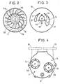
- La figure 3 représente une vue du distributeur d'une pompe à anneau liquide modifiée selon l'invention, le tracé de lumières d'aspiration et de refoulement du distributeur de ladite pompe connue étant représenté en pointillé.
- La figure 4 représente une vue d'extrémité de ladite pompe modifiée, les passages d'aspiration et de refoulement de ladite pompe connue étant représentés en pointillé.
- Les figures 5, 6 et 7 représentent des vues d'ensemble d'un premier, d'un deuxième et d'un troisième systèmes selon l'invention.
- Figure 1 shows an exploded perspective view of a known liquid ring pump.
- Figure 2 shows a sectional view of the body of this pump in operation.
- FIG. 3 shows a view of the dispenser of a modified liquid ring pump according to the invention, the drawing of suction and discharge ports of the dispenser of said known pump being shown in dotted lines.
- FIG. 4 represents an end view of said modified pump, the suction and delivery passages of said known pump being shown in dotted lines.
- Figures 5, 6 and 7 show general views of a first, a second and a third system according to the invention.
Le principe de la pompe à anneau liquide est connu depuis longtemps pour le pompage de gaz notamment pour faire le vide dans une enceinte. Il est par exemple décrit une pompe à anneau liquide connue pour cet usage et représentée à la fig.1 comporte un rotor 11 muni de pales 11A et entraîné par un moteur électrique 10. Ce rotor tourne dans un corps de pompe 12 autour d'un axe 11B parallèle à l'axe 12A de ce corps. Le gaz à pomper pénètre par une bride d'aspiration 13 d'un flasque 14. Il passe ensuite dans le corps de pompe par une lumière d'aspiration 15 d'un distributeur 16 (voir fig.3). Le gaz comprimé est enfin refoulé par une lumière de refoulement 17 du distributeur et évacué par une bride de refoulement du flasque. Un anneau liquide 92 (voir fig.2) est constitué par de l'eau qui a été introduite en volume convenable dans le corps 12 et entraînée en rotation par le rotor 11. Il est plaqué par la force centrifuge contre la paroi cylindrique de ce corps et laisse un volume axial libre pour l'aspiration et la compression du gaz. Il constitue pour le gaz un joint d'étanchéité entre les pales du rotor et la paroi du corps de pompe. Deux pales successives et l'anneau liquide délimitent une chambre tournante dont le volume est grand quand elle passe en regard de la lumière d'aspiration 15 et petit en regard de la lumière de refoulement 17.The principle of the liquid ring pump has been known since long for pumping gas, in particular to create a vacuum in an enclosure. It is for example described a liquid ring pump known for this use and shown in fig.1 comprises a
Les calories produites par la compression du gaz et par les frottements sont absorbées par l'eau de l'anneau liquide, qui doit donc être renouvelée pour éviter un échauffement excessif. C'est pourquoi une alimentation en eau de l'anneau liquide est effectuée en permanence au moyen d'un orifice 19 du flasque, l'eau pénétrant ensuite dans le corps de pompe à travers un orifice d'alimentation 100 du distributeur. Cet excédent d'eau épaissit radialement l'anneau liquide qui déverse en continu le surplus par la lumière de refoulement 17. Des avantages connus de ce type de pompe sont qu'il est robuste et peu sensible à la présence de liquides ou de poussières entraînés par le gaz pompé.The calories produced by the compression of the gas and by friction are absorbed by the water in the liquid ring, which must therefore be renewed to avoid excessive heating. This is why a supply of water to the liquid ring is carried out permanently by means of an
Selon l'invention une pompe analogue est utilisée pour aspirer et refouler une masse à base d'eau. Il est apparu que cette pompe se prêtait au transit de matières molles qui, pénétrant dans le corps de pompe par la lumière d'aspiration 15, se trouvent hachées par les pales du rotor 11. Le broyage est rendu possible par la robustesse du rotor qui équipe ce type de pompes. Pour faciliter le transit des matières et éviter le bouchage de la pompe, celle-ci est adaptée de la façon suivante :
- 1) Les lumières d'aspiration 15 et de refoulement 17 du distributeur connu 16 sont remplacées par des lumières agrandies 21
et 22 comme indiqué sur la figure 3. L'objet de cet agrandissement est principalement d'éviter qu'un objet ayant pu s'introduire dans le réseau sous vide puisse se bloquer à l'entrée de la lumière d'aspiration. C'est pourquoi cette lumière est agrandie jusqu'à pouvoir contenir au minimum un cercle dont le diamètre est le diamètre intérieur de la canalisation de raccordement des water-closets, soit environ 40 mm. - 2) Pour éviter le colmatage des conduits délimités par le flasque 14 et le distributeur 16, les brides d'aspiration 13 et de refoulement 18 sont remplacées par des brides d'aspiration 33 et de refoulement 34 présentant des orifices de diamètre plus importants percés sur la face du flasque 14, de manière que leurs axes soient parallèles aux axes 11B du rotor et 12A du corps de pompe, et qu'ils intersectent les lumières d'aspiration et de refoulement 21
et 22 dans la zone où elles ont été agrandies.
- 1) The
suction 15 anddischarge 17 lights of the knowndistributor 16 are replaced byenlarged lights - 2) To prevent clogging of the conduits delimited by the
flange 14 and thedistributor 16, thesuction 13 anddischarge 18 flanges are replaced bysuction 33 anddischarge 34 flanges having larger diameter holes drilled on the face of theflange 14, so that their axes are parallel to theaxes 11B of the rotor and 12A of the pump body, and that they intersect the suction anddischarge ports
La figure 5 représente un premier système dans lequel la pompe à anneau liquide est raccordée à un réseau de collecte sous vide d'eaux usées. Ce réseau est schématisé par un collecteur 42 auquel est raccordé une cuvette de water-closet munie d'une chasse d'eau et d'une vanne d'évacuation étanche au vide. Cette chasse et cette vanne sont de types connus et ne sont pas représentées. La bride d'aspiration 33 est raccordée au réseau de collecte. La bride de refoulement 34 est connectée par l'intermédiaire du tuyau 41 directement au conduit d'évacuation ou égoût 44 qui est à la pression atmosphérique. Le fonctionnement de la pompe à anneau liquide nécessite une alimentation en eau de faible débit, destinée à maintenir le volume de l'anneau liquide et à assurer le refroidissement. Cette alimentation parvient à l'orifice d'alimentation 19 de la pompe au moyen du conduit 45, le débit étant réglé par la vanne 46.FIG. 5 shows a first system in which the liquid ring pump is connected to a vacuum water collection network for wastewater. This network is shown schematically by a
Dans le système qui vient d'être décrit, la pompe à anneau liquide assure le transfert des gaz, des eaux et des matières solides du réseau sous vide vers l'égoût 44 à la pression atmosphérique, ainsi que le broyage de ces matières solides. Les avantages de l'invention apparaissent clairement puisque d'une part une seule machine tournante suffit à assurer la triple fonction de pompe à vide, de pompe à eau, et de broyeur, que d'autre part le réservoir de stockage n'est pas indispensable et qu'enfin la puissance électrique installée et consommé est beaucoup plus faible que la puissance requise pour une installation avec éjecteurs de même capacité d'aspiration.In the system which has just been described, the liquid ring pump ensures the transfer of gases, water and solid materials from the vacuum network to the
Suivant une disposition préférée représentée également sur la figure 5, un piège est placé en amont de la pompe à anneau liquide pour retenir les particules très lourdes, comme par exemple des objets métalliques, qui auraient pu être introduites, par accident ou par malveillance, dans l'installation de collecte des eaux usées et qui pourraient détériorer la pompe à anneau liquide. Ce piège peut être constitué par une simple caisse 51 à travers laquelle transistent les eaux usées, les orifices d'entrée/sortie 52 et 53 étant placées à la partie supérieure de la caisse de manière que les objets lourds tombent au fond de la caisse et ne parviennent pas à la pompe. La caisse peut être vidée périodiquement au moyen d'une trappe de visite 54.According to a preferred arrangement also shown in FIG. 5, a trap is placed upstream of the liquid ring pump to retain very heavy particles, such as for example metallic objects, which could have been introduced, by accident or maliciously, into the wastewater collection system which could damage the liquid ring pump. This trap can be constituted by a
Suivant une autre disposition préférée également représentée sur la figure 5, il est utile de mettre en place entre le réseau sous vide et la pompe à anneau liquide un clapet anti-retour 55, et à l'amont du clapet un vacuostat 56 capable, par l'intermédiaire d'un relais 57, de mettre en marche la pompe sur un seuil de pression haut et de l'arrêter sur un seuil de pression bas. Ainsi, lorsque l'installation sanitaire n'est que peu ou pas utilisée, la pompe à anneau liquide s'arrête lorsque le seuil de pression bas est atteint, et le clapet se ferme en isolant ainsi l'installation sous vide. En fonction de la fréquence d'emploi des appareils sani taires, le vide se casse petit à petit. La pompe se réenclenche alors sur le seuil de pression haut et évacue l'eau et les matières accumulées dans les tuyauteries.According to another preferred arrangement also shown in FIG. 5, it is useful to set up between the vacuum network and the liquid ring pump a
Un inconvénient du premier système qui vient d'être décrit selon l'invention est la nécessité d'alimenter l'anneau liquide en eau claire, ce qui pénalise la consommation d'eau de l'ensemble de l'installation. Pour pallier cet inconvénient, il est préférable d'introduire, entre la pompe et le collecteur d'évacuation d'un deuxième système selon l'invention, un réservoir de stockage 61 comme il est indiqué sur la figure 6. Ce réservoir est muni d'une cheminée d'aération 62 et d'une tuyauterie de vidange 63 fermée par une vanne 64. Le réservoir est vidé soit périodiquement, soit en continu, par des moyens quelconques non décrits ici, sans que le niveau descende au-dessous d'un niveau minimum situé au-dessus du piquage d'alimentation d'une tuyauterie 65 reliant la base du réservoir au conduit d'aspiration 66 de la pompe à anneau liquide. Ainsi, l'anneau liquide peut être alimenté par recirculation d'une partie des eaux usées, l'écoulement dans le conduit 65 s'effectuant sans pompe auxiliaire, sous l'effet de la dépression créée par la pompe à anneau liquide. Une alimentation en eau claire 45 est cependant nécessaire dans la phase de démarrage de la pompe. Cette alimentation est ensuite coupée par la vanne 46.A drawback of the first system which has just been described according to the invention is the need to supply the liquid ring with clear water, which penalizes the water consumption of the entire installation. To overcome this drawback, it is preferable to introduce, between the pump and the evacuation manifold of a second system according to the invention, a
Dans un tel système comportant un réservoir de stockage une autre disposition préférée également représentée sur la figure 6 consiste à prolonger la conduite de refoulement 71 de la pompe à anneau liquide jusqu'au fond du réservoir. Ainsi, l'air refoulé par la pompe s'échappe de la tuyauterie de refoulement sous forme de bulles. Ce bullage est propice à la dégradation aérobie des matières contenues dans le réservoir.In such a system comprising a storage tank, another preferred arrangement also shown in FIG. 6 consists in extending the
Dans un triosième système selon l'invention représenté sur la figure 7, la pompe à anneau liquide est également utilisée pour la vidange du réservoir de stockage. Plus particulièrement on utilise ici de manière temporaire une possibilité des pompes à anneau liquide qui est connue en elle-même et selon laquelle une telle pompe peut fonctionner en compresseur d'air. Pour effectuer une vidange on ferme une vanne de séparation 81 à travers laquelle se fait la connection du réservoir de stockage au réseau sous vide et on ouvre une vanne d'introduction d'air 82 qui permet une communication avec l'atmosphère. La pompe aspire alors de l'air à pression atmosphérique qu'elle comprime en le refoulant dans le réservoir. On a aussi fermé une vanne 83 située sur la cheminée d'aération du réservoir. Si on ouvre alors une vanne 84 de vidange de réservoir, il en résulte une vidange sous pression de celui-ci. Il est possible ainsi de refouler les eaux usées dans une canalisation de vidange 86 jusqu'à un conduit collecteur 88 situé plus haut que le réservoir.In a third system according to the invention shown in FIG. 7, the liquid ring pump is also used for emptying the storage tank. More particularly, here a temporary use is made of a liquid ring pump which is known in itself and according to which such a pump can operate as an air compressor. To perform a drain on closes a separation valve 81 through which the storage tank is connected to the vacuum network and an
Claims (10)
- un collecteur tubulaire (42) pour recevoir lesdites eaux usées sous la forme de bouchons successifs, ainsi que des masses d'air consécutives à ces bouchons et provenant de l'atmosphère,
- et des moyens de circulation, aspiration et refoulement raccordés à ce collecteur pour aspirer ces bouchons et ces masses d'air consécutives en abaissant la pression d'air dans ledit collecteur à une pression d'aspiration inférieure à la pression atmosphérique, et pour refouler lesdites eaux usées sous une pression d'évacuation supérieure à ladite pression d'aspiration et suffisante pour permettre leur évacuation,
ce système étant caractérisé par le fait que lesdits moyen de circulation, aspiration et refoulement comportent
- une pompe à anneau liquide (P) munie d'un passage d'aspiration (33) raccordé au dit collecteur, d'un passage de refoulement pour l'évacuation desdites eaux usées, et d'un passage d'alimentation en eau pour recevoir un débit minoritaire d'une eau d'alimentation propre à former et/ou entretenir un anneau liquide dans cette pompe,
- et des moyens d'alimentation en eau (45, 46) pour fournir ladite eau d'alimentation.2 / Wastewater evacuation system comprising
- a tubular collector (42) for receiving said wastewater in the form of successive plugs, as well as air masses consecutive to these plugs and coming from the atmosphere,
- and circulation, suction and discharge means connected to this manifold to suck up these plugs and these consecutive air masses by lowering the air pressure in said manifold to a suction pressure below atmospheric pressure, and for discharging said wastewater under an evacuation pressure higher than said suction pressure and sufficient to allow their evacuation,
this system being characterized by the fact that said means of circulation, suction and delivery include
- a liquid ring pump (P) provided with a suction passage (33) connected to said collector, with a discharge passage for the discharge of said waste water, and with a water supply passage for receive a minority flow of supply water suitable for forming and / or maintaining a liquid ring in this pump,
- And water supply means (45, 46) for supplying said feed water.
- une vanne d'introduction d'air (82) qui lorsqu'elle est ouverte fait communiquer ledit passage d'aspiration (33) de ladite pompe à anneau liquide (P) avec l'atmosphère,
- une vanne de séparation (81) qui, lorsqu'elle est fermée, supprime le raccordement de ce passage d'aspiration (33) audit collecteur (42),
- et une canalisation de vidange (86) raccordant une partie basse dudit réservoir de stockage (61) à une zone d'évacuation (88) de manière que, dans une période de stockage pendant laquelle cette vanne d'introduction d'air est fermée et cette vanne de séparation ouverte, cette pompe aspire lesdits bouchons et lesdites masses d'air consécutives et refoule lesdites eaux usées dans ledit réservoir de stockage pour y stocker ces eaux usées, et de manière que, dans une période de vidange pendant laquelle cette vanne d'introduction d'air est ouverte et cette vanne de séparation fermée, cette même pompe aspire un débit d'air à partir de l'atmosphère et refoule ce débit d'air dans ledit réservoir de stockage sous une pression de vidange qui constitue ladite pression d'évacuation et qui est supérieure à la pression atmosphérique et à ladite pression de stockage, grâce à quoi ce débit d'air refoulé refoule lui-même, à travers ladite canalisation de vidange, les eaux usées qui ont été stockées dans ce réservoir pendant une dite période de stockage précédente.6 / System according to claim 5, in that said valves and pipes for emptying said tank comprise
an air introduction valve (82) which, when open, communicates said suction passage (33) of said liquid ring pump (P) with the atmosphere,
a separation valve (81) which, when closed, eliminates the connection of this suction passage (33) to said manifold (42),
- And a drain pipe (86) connecting a lower part of said storage tank (61) to an evacuation zone (88) so that, during a storage period during which this air introduction valve is closed and this separation valve open, this pump sucks said plugs and said consecutive air masses and discharges said waste water into said storage tank to store this waste water there, and so that, during a draining period during which this valve the air introduction valve is open and this separation valve closed, this same pump sucks in an air flow from the atmosphere and discharges this air flow into said storage tank under a drain pressure which constitutes said discharge pressure and which is higher than atmospheric pressure and said storage pressure, whereby this flow of discharged air itself discharges, through said drain pipe, the waste water which has been stored in ns this tank during a so-called previous storage period.
- un corps de pompe (12) présentant une paroi périphérique (12B) généralement cylindrique autour d'un axe de corps (12A),
- un rotor (11) muni de pales (11A), présentant un axe de rotor (11B) et tournant dans ce corps autour de cet axe, ce dernier étant décalé par rapport audit axe de corps,
- un moteur (10) pour entraîner ce rotor,
- un distributeur (16) constituant une paroi au contact de l'espace intérieur audit corps de pompe,
- une lumière d'aspiration (21) et une lumière de refoulement (22) percées dans ce distributeur,
- et un passage d'alimentation (19) permettant d'introduire de l'eau dans ledit corps de manière que l'eau ainsi introduite constitue un anneau liquide entraîné en rotation par lesdites pales du rotor et plaqué par la force centrifuge contre ladite paroi périphérique (12B) et que des chambres de pompage tournantes séparées soient constituées par ces pales et cet anneau et qu'elles aspirent un fluide à pomper à travers ladite lumière d'aspiration et le refoulent à travers ladite lumière de refoulement,
- ce système étant caractérisé par le fait que ladite lumière d'aspira tion (21) et suffisamment large pour contenir un cercle de diamètre 40 mm environ, de manière à faciliter l'aspiration de matières peu résistantes qui peuvent faire parties desdits bouchons.9 / The system of claim 1 wherein said liquid ring pump (P) comprises
- a pump body (12) having a peripheral wall (12B) generally cylindrical around a body axis (12A),
- a rotor (11) provided with blades (11A), having a rotor axis (11B) and rotating in this body around this axis, the latter being offset with respect to said body axis,
- a motor (10) for driving this rotor,
- a distributor (16) constituting a wall in contact with the interior space of said pump body,
- a suction light (21) and a discharge light (22) drilled in this distributor,
- And a feed passage (19) allowing water to be introduced into said body so that the water thus introduced constitutes a liquid ring driven in rotation by said blades of the rotor and pressed by centrifugal force against said wall peripheral (12B) and that separate rotating pumping chambers are formed by these blades and this ring and that they suck a fluid to be pumped through said suction light and discharge it through said discharge light,
- this system being characterized by the fact that said suction light tion (21) and wide enough to contain a circle with a diameter of about 40 mm, so as to facilitate the suction of weak materials which may form part of said plugs.
ce système étant caractérisé par le fait que ledit axe (33A) dudit passage d'aspiration (33) et de préférence celui (34A) dudit passage de refoulement (34) sont sensiblement parallèles auxdits axes de corps (12A) et de rotor (11B) et que leurs prolongements passent sensiblement à travers lesdites lumières d'aspiration (21) et de refoulement (22), respectivement.10 / The system of claim 9, wherein said liquid ring pump (P) is further provided with tubular suction passages (33) and discharge (34) connected respectively to said suction ports (21) and discharge (22) and each having an axis (33A, 34A),
this system being characterized by the fact that said axis (33A) of said suction passage (33) and preferably that (34A) of said discharge passage (34) are substantially parallel to said body (12A) and rotor (11B) axes ) and that their extensions pass substantially through said suction (21) and discharge (22) ports, respectively.
Applications Claiming Priority (2)
| Application Number | Priority Date | Filing Date | Title |
|---|---|---|---|
| FR8803209A FR2628459B1 (en) | 1988-03-11 | 1988-03-11 | WASTE WATER VACUUM DISCHARGE SYSTEM |
| FR8803209 | 1988-03-11 |
Publications (2)
| Publication Number | Publication Date |
|---|---|
| EP0333045A1 true EP0333045A1 (en) | 1989-09-20 |
| EP0333045B1 EP0333045B1 (en) | 1995-09-06 |
Family
ID=9364197
Family Applications (1)
| Application Number | Title | Priority Date | Filing Date |
|---|---|---|---|
| EP19890104226 Expired - Lifetime EP0333045B1 (en) | 1988-03-11 | 1989-03-09 | Vacuum sewage conveying system |
Country Status (6)
| Country | Link |
|---|---|
| EP (1) | EP0333045B1 (en) |
| DE (1) | DE68924081T2 (en) |
| DK (1) | DK172092B1 (en) |
| FI (1) | FI891094A (en) |
| FR (1) | FR2628459B1 (en) |
| NO (1) | NO891008L (en) |
Cited By (8)
| Publication number | Priority date | Publication date | Assignee | Title |
|---|---|---|---|---|
| FR2694317A1 (en) * | 1992-07-28 | 1994-02-04 | Felden Jean Marie | Cleaning and evacuation of toilets in transport systems, e.g. trains, aircraft, etc. - in which treatment stations with chemical and water mixing system are connected to toilets and residues removed by vacuum or pump |
| EP1172492A2 (en) | 2000-07-10 | 2002-01-16 | Evac International Oy | Vacuum system |
| EP1490599A2 (en) * | 2002-03-15 | 2004-12-29 | Water Management Systems | Pump system with vacuum source |
| EP1832689A1 (en) * | 2006-03-06 | 2007-09-12 | ROEDIGER VAKUUM- und HAUSTECHNIK GmbH | Low pressure wastewater device |
| US7878768B2 (en) | 2007-01-19 | 2011-02-01 | David Muhs | Vacuum pump with wear adjustment |
| US8381324B2 (en) | 2006-12-21 | 2013-02-26 | Evac International Oy | Vacuum sewage system |
| RU2509844C2 (en) * | 2008-07-10 | 2014-03-20 | Джетс Ас | Method to control source of vacuum in vacuum sewage system |
| US8998586B2 (en) | 2009-08-24 | 2015-04-07 | David Muhs | Self priming pump assembly with a direct drive vacuum pump |
Families Citing this family (4)
| Publication number | Priority date | Publication date | Assignee | Title |
|---|---|---|---|---|
| FI20011506A (en) * | 2001-07-10 | 2003-01-11 | Evac Int Oy | Vacuum Collection System |
| DE102011016243A1 (en) * | 2011-04-06 | 2012-10-11 | Fraunhofer-Gesellschaft zur Förderung der angewandten Forschung e.V. | Drainage system for use in e.g. home, has waste water tank into which sewage/organic waste is sucked, and devices for generating required low and high pressure on respective suction and pressing sides for sucking and discharging sewage |
| FI127077B (en) | 2016-04-19 | 2017-10-31 | Evac Oy | A method for controlling a vacuum system and a vacuum system |
| CN117432040B (en) * | 2023-12-19 | 2024-03-15 | 山东瀚广建设项目管理有限公司 | Drainage device for construction engineering |
Citations (6)
| Publication number | Priority date | Publication date | Assignee | Title |
|---|---|---|---|---|
| US1492171A (en) * | 1923-04-11 | 1924-04-29 | Irving C Jennings | Sewage ejector |
| FR2127865A5 (en) * | 1971-03-03 | 1972-10-13 | Nash Engineering Co | |
| US3956776A (en) * | 1975-05-28 | 1976-05-18 | Thetford Corporation | Liquid waste material conveying system for toilets and the like |
| FR2308742A1 (en) * | 1975-04-23 | 1976-11-19 | Ifoe Ab | IMPROVEMENTS TO VACUUM SANITATION SYSTEMS WITH COLLECTOR CONTAINER |
| DE3418326A1 (en) * | 1984-05-17 | 1985-11-21 | Willi 4973 Vlotho Cordes | Sewage pumping station |
| DE8708108U1 (en) * | 1987-06-09 | 1987-08-06 | Siemens Ag, 1000 Berlin Und 8000 Muenchen, De |
-
1988
- 1988-03-11 FR FR8803209A patent/FR2628459B1/en not_active Expired - Lifetime
-
1989
- 1989-03-08 FI FI891094A patent/FI891094A/en not_active Application Discontinuation
- 1989-03-09 DE DE1989624081 patent/DE68924081T2/en not_active Expired - Lifetime
- 1989-03-09 EP EP19890104226 patent/EP0333045B1/en not_active Expired - Lifetime
- 1989-03-09 NO NO89891008A patent/NO891008L/en unknown
- 1989-03-10 DK DK117289A patent/DK172092B1/en not_active IP Right Cessation
Patent Citations (6)
| Publication number | Priority date | Publication date | Assignee | Title |
|---|---|---|---|---|
| US1492171A (en) * | 1923-04-11 | 1924-04-29 | Irving C Jennings | Sewage ejector |
| FR2127865A5 (en) * | 1971-03-03 | 1972-10-13 | Nash Engineering Co | |
| FR2308742A1 (en) * | 1975-04-23 | 1976-11-19 | Ifoe Ab | IMPROVEMENTS TO VACUUM SANITATION SYSTEMS WITH COLLECTOR CONTAINER |
| US3956776A (en) * | 1975-05-28 | 1976-05-18 | Thetford Corporation | Liquid waste material conveying system for toilets and the like |
| DE3418326A1 (en) * | 1984-05-17 | 1985-11-21 | Willi 4973 Vlotho Cordes | Sewage pumping station |
| DE8708108U1 (en) * | 1987-06-09 | 1987-08-06 | Siemens Ag, 1000 Berlin Und 8000 Muenchen, De |
Cited By (12)
| Publication number | Priority date | Publication date | Assignee | Title |
|---|---|---|---|---|
| FR2694317A1 (en) * | 1992-07-28 | 1994-02-04 | Felden Jean Marie | Cleaning and evacuation of toilets in transport systems, e.g. trains, aircraft, etc. - in which treatment stations with chemical and water mixing system are connected to toilets and residues removed by vacuum or pump |
| US8246316B2 (en) | 1999-03-22 | 2012-08-21 | David Muhs | Vacuum source and float valve for a self-priming pump |
| EP1172492A2 (en) | 2000-07-10 | 2002-01-16 | Evac International Oy | Vacuum system |
| EP1172492A3 (en) * | 2000-07-10 | 2003-01-22 | Evac International Oy | Vacuum system |
| EP1490599A2 (en) * | 2002-03-15 | 2004-12-29 | Water Management Systems | Pump system with vacuum source |
| EP1490599A4 (en) * | 2002-03-15 | 2007-07-11 | Water Man Systems | Pump system with vacuum source |
| EP1832689A1 (en) * | 2006-03-06 | 2007-09-12 | ROEDIGER VAKUUM- und HAUSTECHNIK GmbH | Low pressure wastewater device |
| US8381324B2 (en) | 2006-12-21 | 2013-02-26 | Evac International Oy | Vacuum sewage system |
| US7878768B2 (en) | 2007-01-19 | 2011-02-01 | David Muhs | Vacuum pump with wear adjustment |
| RU2509844C2 (en) * | 2008-07-10 | 2014-03-20 | Джетс Ас | Method to control source of vacuum in vacuum sewage system |
| US9932114B2 (en) | 2008-07-10 | 2018-04-03 | Jets As | Method for controlling the vacuum generator(s) in a vacuum sewage system |
| US8998586B2 (en) | 2009-08-24 | 2015-04-07 | David Muhs | Self priming pump assembly with a direct drive vacuum pump |
Also Published As
| Publication number | Publication date |
|---|---|
| DK172092B1 (en) | 1997-10-20 |
| DE68924081T2 (en) | 1996-02-01 |
| FI891094A (en) | 1989-09-12 |
| DK117289A (en) | 1989-09-12 |
| NO891008L (en) | 1989-09-12 |
| DE68924081D1 (en) | 1995-10-12 |
| EP0333045B1 (en) | 1995-09-06 |
| FI891094A0 (en) | 1989-03-08 |
| NO891008D0 (en) | 1989-03-09 |
| DK117289D0 (en) | 1989-03-10 |
| FR2628459A1 (en) | 1989-09-15 |
| FR2628459B1 (en) | 1992-07-31 |
Similar Documents
| Publication | Publication Date | Title |
|---|---|---|
| EP0333045B1 (en) | Vacuum sewage conveying system | |
| FR2774136A1 (en) | System of compression pumping for a multiphase fluid | |
| WO2007132073A1 (en) | System for cleaning an oil tank and method of cleaning an oil tank | |
| EP2307624B1 (en) | Automatic and rapid opening flush system for full-tank discharge | |
| EP0561899B1 (en) | Water closet | |
| EP0065899B1 (en) | Water closet with mechanical evacuation having an accessible and removable evacuation chamber inside the toilet bowl | |
| EP0058610B1 (en) | Method and installation for producing a high vacuum using a single-stage liquid-ring pump | |
| EP1091812B1 (en) | Method for cleaning an oil storage tank and device for implementing same | |
| CA3138466A1 (en) | Device and process for pumping low vacuum evaporation products | |
| FR2663373A1 (en) | Method and device for establishing a partial vacuum in a zone of permeable ground isolated from the atmosphere by a leaktight membrane | |
| EP3891343B1 (en) | Low water-consumption pressurised toilet bowl system | |
| FR2974551A1 (en) | COMPACT BLACK WATER STORAGE AND EXHAUST SYSTEM OF A VEHICLE WITH CASSETTE TOILET. | |
| FR2612419A1 (en) | Valve-free filter with automatic unblocking | |
| FR2491521A1 (en) | COLLECTOR OF WASTEWATER | |
| EP3097016B1 (en) | Method and system for managing the grey water in an aircraft | |
| FR2651158A1 (en) | Device for the hydraulic extraction of materials in suspension | |
| BE1021893B1 (en) | PUMPING UNIT, PUMPING STATION, PUMPING AREA AND METHOD FOR PUMPING A LIQUID. | |
| FR2601084A1 (en) | CENTRIFUGAL PUMP FOR DELIVERY OF GAS-CONTAINING FLUIDS | |
| FR2914660A1 (en) | Flushing device useful in a system for purifying the consumed water, comprises a reservoir having an inlet and an outlet, a sealed seat surrounding the outlet, a floatable stopper moving vertically in the reservoir, and a floatable body | |
| FR2565277A1 (en) | Improvements made to pump- or pulveriser-type W.C. bowls | |
| FR2723768A1 (en) | Pneumatic pump for solids in suspension | |
| EP0051571A1 (en) | Emulsion siphon | |
| FR2767848A1 (en) | Combined water storage tank and W.C. flushing cistern installation | |
| FR2473459A1 (en) | VACUUM DRAINAGE INSTALLATION OF WASTEWATER FOR BOATS | |
| FR2902813A1 (en) | Grinder-pump assembly for e.g. lavatory installation, has motor equipped with wheel that ensures pumping and grinding of matter evacuated form lavatory bowl and is formed by pressing of metal blank, and blade curved to present helical shape |
Legal Events
| Date | Code | Title | Description |
|---|---|---|---|
| PUAI | Public reference made under article 153(3) epc to a published international application that has entered the european phase |
Free format text: ORIGINAL CODE: 0009012 |
|
| AK | Designated contracting states |
Kind code of ref document: A1 Designated state(s): BE DE ES FR GB IT NL SE |
|
| 17P | Request for examination filed |
Effective date: 19900319 |
|
| 17Q | First examination report despatched |
Effective date: 19910208 |
|
| RAP1 | Party data changed (applicant data changed or rights of an application transferred) |
Owner name: EVAC S.A.E.D. |
|
| GRAA | (expected) grant |
Free format text: ORIGINAL CODE: 0009210 |
|
| AK | Designated contracting states |
Kind code of ref document: B1 Designated state(s): BE DE ES FR GB IT NL SE |
|
| PG25 | Lapsed in a contracting state [announced via postgrant information from national office to epo] |
Ref country code: IT Free format text: LAPSE BECAUSE OF FAILURE TO SUBMIT A TRANSLATION OF THE DESCRIPTION OR TO PAY THE FEE WITHIN THE PRE;WARNING: LAPSES OF ITALIAN PATENTS WITH EFFECTIVE DATE BEFORE 2007 MAY HAVE OCCURRED AT ANY TIME BEFORE 2007. THE CORRECT EFFECTIVE DATE MAY BE DIFFERENT FROM THE ONE RECORDED.SCRIBED TIME-LIMIT Effective date: 19950906 Ref country code: NL Free format text: LAPSE BECAUSE OF FAILURE TO SUBMIT A TRANSLATION OF THE DESCRIPTION OR TO PAY THE FEE WITHIN THE PRESCRIBED TIME-LIMIT Effective date: 19950906 Ref country code: ES Free format text: THE PATENT HAS BEEN ANNULLED BY A DECISION OF A NATIONAL AUTHORITY Effective date: 19950906 |
|
| GBT | Gb: translation of ep patent filed (gb section 77(6)(a)/1977) |
Effective date: 19950821 |
|
| REF | Corresponds to: |
Ref document number: 68924081 Country of ref document: DE Date of ref document: 19951012 |
|
| PG25 | Lapsed in a contracting state [announced via postgrant information from national office to epo] |
Ref country code: SE Effective date: 19951206 |
|
| NLV1 | Nl: lapsed or annulled due to failure to fulfill the requirements of art. 29p and 29m of the patents act | ||
| PG25 | Lapsed in a contracting state [announced via postgrant information from national office to epo] |
Ref country code: BE Effective date: 19960331 |
|
| PLBE | No opposition filed within time limit |
Free format text: ORIGINAL CODE: 0009261 |
|
| STAA | Information on the status of an ep patent application or granted ep patent |
Free format text: STATUS: NO OPPOSITION FILED WITHIN TIME LIMIT |
|
| 26N | No opposition filed | ||
| BERE | Be: lapsed |
Owner name: EVAC S.A.E.D. Effective date: 19960331 |
|
| REG | Reference to a national code |
Ref country code: GB Ref legal event code: IF02 |
|
| REG | Reference to a national code |
Ref country code: FR Ref legal event code: CA Ref country code: FR Ref legal event code: CD Ref country code: FR Ref legal event code: CJ |
|
| PGFP | Annual fee paid to national office [announced via postgrant information from national office to epo] |
Ref country code: DE Payment date: 20080610 Year of fee payment: 20 |
|
| PGFP | Annual fee paid to national office [announced via postgrant information from national office to epo] |
Ref country code: FR Payment date: 20080613 Year of fee payment: 20 |
|
| PGFP | Annual fee paid to national office [announced via postgrant information from national office to epo] |
Ref country code: GB Payment date: 20080620 Year of fee payment: 20 |
|
| REG | Reference to a national code |
Ref country code: GB Ref legal event code: PE20 Expiry date: 20090308 |
|
| PG25 | Lapsed in a contracting state [announced via postgrant information from national office to epo] |
Ref country code: GB Free format text: LAPSE BECAUSE OF EXPIRATION OF PROTECTION Effective date: 20090308 |
|
| REG | Reference to a national code |
Ref country code: DE Ref legal event code: R043 Ref document number: 68924081 Country of ref document: DE Effective date: 20111220 |
|
| REG | Reference to a national code |
Ref country code: DE Ref legal event code: R082 Ref document number: 68924081 Country of ref document: DE Representative=s name: GRAF GLUECK KRITZENBERGER, DE |
|
| REG | Reference to a national code |
Ref country code: DE Ref legal event code: R082 Ref document number: 68924081 Country of ref document: DE Representative=s name: GLUECK - KRITZENBERGER PATENTANWAELTE PARTGMBB, DE Effective date: 20140317 Ref country code: DE Ref legal event code: R082 Ref document number: 68924081 Country of ref document: DE Representative=s name: GRAF GLUECK KRITZENBERGER, DE Effective date: 20140317 Ref country code: DE Ref legal event code: R081 Ref document number: 68924081 Country of ref document: DE Owner name: EVAC OY, FI Free format text: FORMER OWNER: EVAC INTERNATIONAL OY, ESPOO, FI Effective date: 20140317 |
|
| REG | Reference to a national code |
Ref country code: DE Ref legal event code: R040 Ref document number: 68924081 Country of ref document: DE Ref country code: DE Ref legal event code: R097 Ref document number: 68924081 Country of ref document: DE |