EP0332810A2 - Receding folding top for a motor vehicle - Google Patents
Receding folding top for a motor vehicle Download PDFInfo
- Publication number
- EP0332810A2 EP0332810A2 EP89100914A EP89100914A EP0332810A2 EP 0332810 A2 EP0332810 A2 EP 0332810A2 EP 89100914 A EP89100914 A EP 89100914A EP 89100914 A EP89100914 A EP 89100914A EP 0332810 A2 EP0332810 A2 EP 0332810A2
- Authority
- EP
- European Patent Office
- Prior art keywords
- folding top
- rear window
- window
- retractable
- folding
- Prior art date
- Legal status (The legal status is an assumption and is not a legal conclusion. Google has not performed a legal analysis and makes no representation as to the accuracy of the status listed.)
- Granted
Links
Images


Classifications
-
- B—PERFORMING OPERATIONS; TRANSPORTING
- B60—VEHICLES IN GENERAL
- B60J—WINDOWS, WINDSCREENS, NON-FIXED ROOFS, DOORS, OR SIMILAR DEVICES FOR VEHICLES; REMOVABLE EXTERNAL PROTECTIVE COVERINGS SPECIALLY ADAPTED FOR VEHICLES
- B60J1/00—Windows; Windscreens; Accessories therefor
- B60J1/18—Windows; Windscreens; Accessories therefor arranged at the vehicle rear
- B60J1/1807—Windows; Windscreens; Accessories therefor arranged at the vehicle rear movable for vehicles with convertible top
- B60J1/1815—Windows; Windscreens; Accessories therefor arranged at the vehicle rear movable for vehicles with convertible top non-adjustably mounted in and moving with the soft-top cover
Definitions
- the invention relates to a retractable folding roof of a motor vehicle, with the features specified in the preamble of the main claim.
- Such a folding top is already known from DE-OS 34 16 330, which has a glass rear window firmly connected to the folding top, which can be curved and extend into the side areas of the folding top.
- the rear window is supported on both sides approximately in the central area by a supporting strut articulated to the convertible top linkage, which strains the folding top to the outside in the closed position and thereby tensions it.
- the rear window is forcibly pivoted into the storage compartment via the support struts. It is particularly disadvantageous that the rear window is not adequately held.
- the rear window When driving over uneven ground, the rear window can perform tilting movements around the articulation points of the support struts, which cause noise and, at least after some time, the tension on the folding top to decrease.
- the support struts provided on the central side areas of the rear window when the folding top is tensioned large bending moments are exerted on the rear window, which can easily break as a result.
- the rear window firmly connected to the folding top is subjected to an uneven load.
- a folding top with a glass rear window is known, which is fastened to the web of a U-shaped tensioning bracket so as to be pivotable about a transverse axis.
- Several straps each running from a front cross bow to the upper edge of the rear window pivot the rear window in front of the rear opening when the folding top is closed.
- the folding top is placed in a rear storage compartment into which the rear window swings when the seat belts are relaxed. It is particularly disadvantageous that the rear window is not adequately held in its closed position by the belts. When driving over uneven ground, the rear window can perform vertical movements, which cause the belts to stretch after some time.
- the rear window is not close to the inner edge of the rear window, so that moisture can penetrate into the vehicle interior.
- the rear window is also not adequately held in the storage compartment, since after swiveling in it only bears with an edge area at the bottom of the storage compartment under its gravity and can be thrown up when driving over uneven ground and can be destroyed or damaged in the subsequent impact on the floor of the storage compartment.
- the invention has for its object to provide a retractable folding top according to the preamble of the main claim, in which even a large, up to the side areas curved glass rear window only slightly and evenly loaded and in the closed position of the The folding top and the storage compartment are adequately held.
- the folding top should also have a headliner with thermal insulation.
- the rear window is forcibly moved completely into the storage compartment when the folding top is opened and when the folding top is closed in front of the rear opening in the folding top via a simple mechanism formed by lateral four-bar joints and a control rod.
- the rear window is held in every position of the folding top.
- the rear window can for example be made of curved glass and provided with heating wires.
- the folding roof can also have a headliner, for example, with thermal insulation, so that a vehicle provided with such a folding roof corresponds in terms of sound and heat insulation and in the rearward view approximately to a vehicle with a fixed roof.
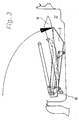
- the folding top 1 of a motor vehicle shown by a dash-dotted line has a rear opening 2, to which an adjustable rear window 3 is assigned. Due to the symmetrical design of the folding top with respect to the longitudinal axis of the motor vehicle, the parts opposite to the laterally arranged components are only specified in exceptional cases.
- the rear window 3 bears against the edge region of the rear opening 2 from the inside.
- a folding linkage supporting the folding top 1 has a front tensioning rod 4 and a rear tensioning rod 5 on both sides of the rear window 3, which are pivotably connected in a joint 6 about a transverse axis.
- the front and rear tensioning rods 4, 5 form an over-center mechanism which, in the illustrated closed position of the folding top on the rear window 3, causes an outward tensioning force.
- the Tension can be designed so that the rear window 3 is always moisture-tight against the inner edge region of the rear opening 2 in the closed position of the folding top, without significantly loading the rear window 3.
- On both sides of the rear window 3 are each formed as a wishbone support members 7, 7 'about a transverse axis 8, 8' pivotally attached to the rear window 3.
- the parallel support members 7, 7 ' are each pivoted at their free end about a transverse axis 8, 8' parallel axis 9, 9 'on the rear tie rod 5.
- the rear window 3 is therefore supported on its sides by support members 7, 7 ', which form four joints, on the laterally opposite rear tie rods 5.
- a laterally arranged control rod 10 is articulated on the one hand with the support member 7 and on the other hand with the front tension rod 4, so that the rear window 3 is held in every position of the folding top 1.
- the laterally opposite front and rear tie rods 4, 5, the support members 7, 7 ', and the control rods 10 have a larger lateral distance to the width of the rear window.
- the rear window 3 is forcibly inserted fully into a rear storage compartment 11 when the folding top 1 is opened and closed, either in front of the rear opening 2 or together with the folding top 1 and its top linkage.
- the transverse axes 8, 8 ' are formed in the embodiment on the frameless rear window 3. Likewise, the transverse axes 8, 8 'could be formed on a frame of the rear window 3.
- a connecting rod 12 can be omitted, which in the exemplary embodiment is articulated to the support members 7, 7 'and connects them.
- the connecting rod 12 tensions in the edge area the rear window 3 avoided when adjusting the four joints.
- the respective rear end of the rear tensioning rod 5 is fastened to the tensioning bracket 14 so as to be pivotable about a pivot axis 13 extending transversely in the web region of a U-shaped tensioning bracket 14.
- the folding top 1 is fastened with its rear lower region to the tensioning bracket 14, which can be locked in the closed position of the folding top 1 by a locking device (not shown) and causes the folding top 1 to be tensioned.
- the clamping bracket 14 can be pivoted upward in the end regions of its legs, which are directed forward in the closed position of the folding top 1, about an axis 16 running in the transverse direction of the body.
- the clamping bracket 14 is shown pivoted up in the direction of the arrow, the rear window 3, the front 4 and rear clamping rod 5, the control rod 10 and the connecting rod 12 being shifted accordingly.
- a swiveling up of the clamping bracket 14 is required in the exemplary embodiment before the folding top is introduced into the receiving compartment so that a cover, not shown, which closes the upper opening of the receiving compartment 11 and can be swung up about a rear transverse axis.
- the tensioning bracket 14 and the folding top with its folding top linkage in the direction of the arrow can be completely inserted into the receiving compartment.
- the axle 16 fixed to the body is shifted downward into the receiving compartment 11.
- the axis 16 is formed on a height-adjustable actuator, not shown. If the folding top is closed, the actuator moves upwards, so that the axis 16 reaches the superscript position shown in FIGS. 1 and 2.
- the actuator can be shifted in height, for example, by means of a hydraulic or pneumatic cylinder.
- the rear window is made of glass arched into the side areas and provided with heating wires.
- the folding top has a headlining (not shown) with thermal insulation, which is inserted with the headlining in the receiving compartment in FIG. After the entire folding top has been introduced into the storage compartment, the latter is closed by the cover, not shown. The folding top can now be carried inconspicuously and protected in the vehicle and removed from the storage compartment if necessary.
- the rear lower region of the rear window 3, which is in the closed position, is shown in a longitudinal section in FIG.
- the rear window 3 can have a frame 17, as in FIG. 4, which is connected to the rear window 3, for example by an adhesive 18.
- An elastic, circumferential window seal 19 is vulcanized onto the edge region of the rear window 3.
- an elastic outer seal 20 is fastened, which, in the closed position of the folding top 1 shown, contacts the rear window 3 from the outside.
- the outer seal 20 cooperates with the washer seal 19 in the exemplary embodiment.
- a window seal or outer seal which, in the closed position of the folding top with the rear window or the edge region of the rear opening, seals the rear opening in a moisture-impermeable manner. Tooth-like sealing lips are formed on the sealing surfaces of the outer seal 20 and the disk seal 19.
- a strip-shaped metal insert 21 is provided in the outer seal 20 for stiffening brought in. The edge of the rear opening 2 forms a loop into which a rod-shaped metal reinforcement 22 is inserted.
- FIG. 1 An alternative sealing arrangement is shown in FIG.
- the window seal 19 ' is not vulcanized on the rear window 3 but on the frame 17 of the rear window 3.
- the window seal 19 'does not interact with the outer seal 20' but with the inner edge region of the rear opening 2.
- a metal insert 21 ', 21' is introduced in the disc seal 19 'and in the outer seal 20' .
- the edge of the rear opening 2 forms a loop into which a circumferential strip-shaped metal reinforcement 22 'is inserted.
- a window seal 19 ' is vulcanized, which has a first region 23 and an outer, second cross-section which is approximately semicircular in cross-section.
- the edge of the rear opening 2 forms a loop into which a circumferentially cylindrical metal reinforcement 22 is inserted.
- the edge region of the rear opening 2 thickened by the metal reinforcement 22 bears against the first region 23, while the region adjacent to the thickened edge region of the rear opening 2 interacts with the second region of the window seal 19.
- the two areas 23, 24 of the window seal 19 ' are provided on the surface with tooth-like sealing lips which run parallel to the adjacent edge of the rear window 3.
Abstract
Description
Die Erfindung betrifft ein versenkbares Faltverdeck eines Kraftfahrzeugs, mit den im Oberbegriff des Hauptanspruchs angegebenen Merkmalen.The invention relates to a retractable folding roof of a motor vehicle, with the features specified in the preamble of the main claim.
Ein derartiges Faltverdeck ist bereits aus der DE-OS 34 16 330 bekannt, das eine mit dem Faltverdeck fest verbundene Heckscheibe aus Glas aufweist, die gekrümmt ausgebildet bis in die Seitenbereiche des Faltverdecks verlaufen kann. Die Heckscheibe ist an beiden Seiten jeweils etwa im mittleren Bereich von einer mit dem Verdeckgestänge gelenkig verbundenen Stützstrebe gestützt, die das Faltverdeck in Schließstellung nach außen belastet und dadurch spannt. Beim Einbringen des Faltverdecks in ein hinteres Aufnahmefach wird die Heckscheibe über die Stützstreben zwangsweise in das Aufnahmefach eingeschwenkt. Besonders nachteilig ist, daß die Heckscheibe nicht ausreichend festgehalten ist. Beim Überfahren von Bodenunebenheiten kann die Heckscheibe Kippbewegungen um die Anlenkstellen der Stützstreben ausführen, die Geräusche und zumindest nach einiger Zeit ein Nachlassen der Spannung des Faltverdecks bewirken. Durch die an den mittleren Seitenbereichen der Heckscheibe vorgesehenen Stützstreben werden beim Spannen des Faltverdecks große Biegemomente auf die Heckscheibe ausgeübt, die dadurch leicht brechen kann. Bei Fertigungsungenauigkeiten der Heckscheibe und/oder des Faltverdecks wird die mit dem Faltverdeck fest verbundene Heckscheibe ungleich belastet.Such a folding top is already known from DE-OS 34 16 330, which has a glass rear window firmly connected to the folding top, which can be curved and extend into the side areas of the folding top. The rear window is supported on both sides approximately in the central area by a supporting strut articulated to the convertible top linkage, which strains the folding top to the outside in the closed position and thereby tensions it. When the folding top is inserted into a rear storage compartment, the rear window is forcibly pivoted into the storage compartment via the support struts. It is particularly disadvantageous that the rear window is not adequately held. When driving over uneven ground, the rear window can perform tilting movements around the articulation points of the support struts, which cause noise and, at least after some time, the tension on the folding top to decrease. Through the support struts provided on the central side areas of the rear window when the folding top is tensioned, large bending moments are exerted on the rear window, which can easily break as a result. In the event of manufacturing inaccuracies in the rear window and / or the folding top, the rear window firmly connected to the folding top is subjected to an uneven load.
Aus der EP-A-0 246 201 ist ein Faltverdeck mit einer Heckscheibe aus Glas bekannt, die an dem Steg eines U-förmigen Spannbügels um eine Querachse schwenkbar befestigt ist. Mehrere jeweils von einem vorderen Querspriegel zum oberen Rand der Heckscheibe verlaufende Gurte schwenken die Heckscheibe beim Schließen des Faltverdecks vor die Hecköffnung. Bei Nichtgebrauch wird das Faltverdeck in ein hinteres Aufnahmefach eingebracht, in das die Heckscheibe bei entspannten Gurten einschwenkt. Besonders nachteilig ist, daß die Heckscheibe in ihrer Schließstellung von den Gurten nicht ausreichend festgehalten ist. Beim Überfahren von Bodenunebenheiten kann die Heckscheibe vertikale Bewegungen ausführen, die nach einiger Zeit eine Dehnung der Gurte bewirken. Bei gedehnten Gurten liegt jedoch die Heckscheibe nicht dicht an dem inneren Rand der Heckscheibe an, so daß Feuchtigkeit in das Fahrzeuginnere eindringen kann. Die Heckscheibe ist auch im Aufnahmefach nicht ausreichend festgehalten, da sie nach dem Einschwenken lediglich mit einem Randbereich am Boden des Aufnahmefaches unter ihrer Schwerkraft anliegt und beim Überfahren von Bodenunebeneheiten hochgeschleudert und beim nachfolgenden Aufprall am Boden des Aufnahmefaches zerstört oder beschädigt werden kann.From EP-A-0 246 201 a folding top with a glass rear window is known, which is fastened to the web of a U-shaped tensioning bracket so as to be pivotable about a transverse axis. Several straps each running from a front cross bow to the upper edge of the rear window pivot the rear window in front of the rear opening when the folding top is closed. When not in use, the folding top is placed in a rear storage compartment into which the rear window swings when the seat belts are relaxed. It is particularly disadvantageous that the rear window is not adequately held in its closed position by the belts. When driving over uneven ground, the rear window can perform vertical movements, which cause the belts to stretch after some time. With stretched belts, however, the rear window is not close to the inner edge of the rear window, so that moisture can penetrate into the vehicle interior. The rear window is also not adequately held in the storage compartment, since after swiveling in it only bears with an edge area at the bottom of the storage compartment under its gravity and can be thrown up when driving over uneven ground and can be destroyed or damaged in the subsequent impact on the floor of the storage compartment.
Der Erfindung liegt die Aufgabe zugrunde, ein versenkbares Faltverdeck nach dem Oberbegriff des Hauptanspruchs anzugeben, bei dem auch eine große, bis in die Seitenbereiche gekrümmte Heckscheibe aus Glas nur gering und gleichmäßig belastet und in Schließstellung des Faltverdecks sowie während der Aufbewahrung im Aufnahmefach ausreichend festgehalten ist. Darüber hinaus soll das Faltverdeck auch einen Himmel mit einer thermischen Isolierung aufweisen können.The invention has for its object to provide a retractable folding top according to the preamble of the main claim, in which even a large, up to the side areas curved glass rear window only slightly and evenly loaded and in the closed position of the The folding top and the storage compartment are adequately held. In addition, the folding top should also have a headliner with thermal insulation.
Diese Aufgabe ist durch die im Kennzeichen des Hauptanspruchs angegebenen Merkmale gelöst. Besonders vorteilhaft ist, daß die Heckscheibe über einen einfachen, durch seitliche Viergelenke und eine Steuerstange gebildeten Mechanismus zwangsweise beim Öffnen des Faltverdecks vollständig in das Aufnahmefach und beim Schließen des Faltverdecks vor die Hecköffnung im Faltverdeck verlagert wird. Auf diese vorteilhafte Weise ist die Heckscheibe in jeder Lage des Faltverdecks festgehalten. Um ein in Schließstellung dichtes Anliegen der Heckscheibe an dem inneren Randbereich der Hecköffnung zu erreichen, ist lediglich eine geringe Anpreßkraft erforderlich. Durch die seitliche Abstützung der Heckscheibe über jeweils zwei mit Abstand hintereinander angeordnete Stützglieder wird diese nur gering belastet. Die Heckscheibe kann beispielsweise aus Glas gekrümmt gefertigt und mit Heizdrähten versehen sein. Das Faltverdeck kann auch einen Himmel beispielsweise mit thermischer Isolierung aufweisen, so daß ein mit einem derartigen Faltverdeck versehenes Fahrzeug in der Schall- und Wärmeisolierung und in der Sicht nach rückwärts etwa einem Fahrzeug mit feststehendem Dach entspricht.This object is achieved by the features specified in the characterizing part of the main claim. It is particularly advantageous that the rear window is forcibly moved completely into the storage compartment when the folding top is opened and when the folding top is closed in front of the rear opening in the folding top via a simple mechanism formed by lateral four-bar joints and a control rod. In this advantageous manner, the rear window is held in every position of the folding top. In order to achieve a tight fit of the rear window against the inner edge region of the rear opening in the closed position, only a small contact pressure is required. Due to the lateral support of the rear window via two spaced-apart support members, this is only slightly loaded. The rear window can for example be made of curved glass and provided with heating wires. The folding roof can also have a headliner, for example, with thermal insulation, so that a vehicle provided with such a folding roof corresponds in terms of sound and heat insulation and in the rearward view approximately to a vehicle with a fixed roof.
Vorteilhafte Ausgestaltungen der Erfindung sind Gegenstand von Unteransprüchen.Advantageous embodiments of the invention are the subject of dependent claims.
Ein Ausführungsbeispiel der Erfindung wird anhand einer Zeichnung näher erläutert. Es zeigen:
- Figur 1 einen vertikalen Längsschnitt durch die Heckscheibe des Faltverdecks,
Figur 2 eine Figur 1 entsprechende Ansicht bei hochgeschwenktem Spannbügel,Figur 3 eine Figur 1 entsprechende Ansicht nach dem Einbringen des Faltverdecks in das Aufnahmefach,Figuren 5 bis 6 unterschiedliche Scheibendichtungen der in ihrem hinteren unteren Randbereich in einem Längsschnitt dargestellten Heckscheibe.
- FIG. 1 shows a vertical longitudinal section through the rear window of the folding top,
- FIG. 2 shows a view corresponding to FIG. 1 with the clamping bracket pivoted up,
- 3 shows a view corresponding to FIG. 1 after the folding top has been introduced into the storage compartment, FIG.
- Figures 5 to 6 different window seals of the rear window shown in its rear lower edge region in a longitudinal section.
Das in Figur 1 durch eine strichpunktierte Linie dargestellte Faltverdeck 1 eines Kraftfahrzeugs weist eine Hecköffnung 2 auf, der eine verstellbare Heckscheibe 3 zugeordnet ist. Aufgrund der zur Längsachse des Kraftfahrzeugs symmetrischen Ausbildung des Faltverdecks werden die zu seitlich angeordneten Bauteilen gegenüberliegenden Teile nur in Ausnahmefällen angegeben. In der dargestellten Schließstellung des Faltverdecks 1 liegt die Heckscheibe 3 von innen an dem Randbereich der Hecköffnung 2 an. Ein das Faltverdeck 1 stützendes Verdeckgestänge weist an beiden Seiten der Heckscheibe 3 je eine vordere Spannstange 4 und eine hintere Spannstange 5 auf, die in einem Gelenk 6 um eine quer verlaufende Achse schwenkbar verbunden sind. Jeweils die vordere und hintere Spannstange 4, 5 bilden einen Übertotpunktmechanismus, der in der dargestellten Schließstellung des Faltverdecks an der Heckscheibe 3 eine nach außen gerichtete Spannkraft bewirkt. Die Spannkraft kann so ausgelegt werden, daß die Heckscheibe 3 in Schließstellung des Faltverdecks stets feuchtigkeitsdicht an dem inneren Randbereich der Hecköffnung 2 anliegt, ohne die Heckscheibe 3 wesentlich zu belasten. An beiden Seiten der Heckscheibe 3 sind jeweils zwei als Dreieckslenker ausgebildete Stützglieder 7, 7′ um je eine Querachse 8, 8′ schwenkbar an der Heckscheibe 3 befestigt. Die im Ausführungsbeispiel parallelen Stützglieder 7, 7′ sind jeweils an ihrem freien Ende um eine zu den Querachsen 8, 8′ parallele Achse 9, 9′ schwenkbar an der hinteren Spannstange 5 angelenkt. Die Heckscheibe 3 ist demnach an ihren Seiten durch Stützglieder 7, 7′, die Viergelenke bilden, an den seitlich gegenüberliegenden hinteren Spannstangen 5 abgestützt. Jeweils eine seitlich angeordnete Steuerstange 10 ist einerseits mit dem Stützglied 7 und andererseits mit der vorderen Spannstange 4 gelenkig verbunden, so daß die Heckscheibe 3 in jeder Lage des Faltverdecks 1 festgehalten ist. Die jeweils seitlich gegenüberliegenden vorderen und hinteren Spannstangen 4, 5, die Stützglieder 7, 7′, sowie die Steuerstangen 10 weisen einen zur Breite der Heckscheibe größeren seitlichen Abstand auf. Über die Viergelenke und die Steuerstangen 10 wird die Heckscheibe 3 zwangsweise beim Öffnen und Schließen des Faltverdecks 1 entweder vor die Hecköffnung 2 oder zusammen mit dem Faltverdeck 1 und seinem Verdeckgestänge in ein hinteres Aufnahmefach 11 vollständig eingebracht. Die Querachsen 8, 8′ sind bei dem Ausführungsbeispiel an der rahmenlosen Heckscheibe 3 ausgebildet. Ebenso könnten die Querachsen 8, 8′ an einem Rahmen der Heckscheibe 3 ausgebildet sein. In diesem Fall kann eine Verbindungsstange 12 entfallen, die im Ausführungsbeispiel gelenkig an den Stützgliedern 7, 7′ befestigt ist und diese verbindet. Durch die Verbindungsstange 12 werden Spannungen im Randbereich der Heckscheibe 3 beim Verstellen der Viergelenke vermieden. Das jeweils hintere Ende der hinteren Spannstange 5 ist um eine im Stegbereich eines U-förmigen Spannbügels 14 in Querrichtung verlaufende Schwenkachse 13 schwenkbar an dem Spannbügel 14 befestigt. Das Faltverdeck 1 ist mit seinem hinteren unteren Bereich an dem Spannbügel 14 befestigt, der in Schließstellung des Faltverdecks 1 von einer nicht dargestellten Arretierungseinrichtung feststellbar ist und ein Spannen des Faltverdecks 1 bewirkt. Der Spannbügel 14 ist in den Endbereichen seiner in Schließstellung des Faltverdecks 1 nach vorne gerichteten Schenkel um eine in Querrichtung verlaufende karosseriefeste Achse 16 nach oben schwenkbar.The folding top 1 of a motor vehicle shown by a dash-dotted line has a
In Figur 2 ist der Spannbügel 14 in Pfeilrichtung hochgeschwenkt dargestellt, wobei die Heckscheibe 3 die vordere 4 und hintere Spannstange 5, die Steuerstange 10 und die Verbindungsstange 12 entsprechend mitverlagert werden. Ein Hochschwenken des Spannbügels 14 ist bei dem Ausführungsbeispiel vor dem Einbringen des Faltverdecks in das Aufnahmefach erforderlich, damit ein die obere Öffnung des Aufnahmefaches 11 verschließender, nicht dargestellter Deckel um eine hintere Querachse hochschwenkbar ist.In Figure 2, the
Gemäß Figur 3 kann nach dem Hochschwenken des Spannbügels 14 und des nicht dargestellten Deckels die Heckscheibe 3, der Spannbügel 14 und das Faltverdeck mit seinem Verdeckgestänge in Pfeilrichtung vollständig in das Aufnahmefach eingebracht werden. Wie in der Figur dargestellt wird dabei die karosseriefeste Achse 16 nach unten in das Aufnahmefach 11 verlagert. Hierzu ist die Achse 16 an einem nicht dargestellten höhenverstellbaren Stellglied ausgebildet. Wird das Faltverdeck geschlossen, so verlagert sich das Stellglied nach oben, so daß die Achse 16 in die hochgestellte, in den Figuren 1 und 2 abgebildete Lage gelangt. Ein Höhenverlagerung des Stellgliedes kann beispielsweise über einen Hydraulik-oder Pneumatikzylinder erfolgen. Bei dem Ausführungsbeispiel ist die Heckscheibe aus Glas bis in die Seitenbereiche gewölbt gefertigt und mit Heizdrähten versehen. Das Faltverdeck weist einen nicht dargestellten Himmel mit einer thermischen Isolierung auf, die in Figur 3 mit dem Himmel in das Aufnahmefach eingebracht ist. Nach dem Einbringen des gesamten Faltverdecks in das Aufnahmefach wird dieses von dem nicht dargestellten Deckel verschlossen. Das Faltverdeck kann nun unauffällig und geschützt im Fahrzeug mitgeführt und bei Bedarf dem Aufnahmefach entnommen werden.According to FIG. 3, after swinging up the
Der hintere untere Bereich der in Schließstellung befindlichen Heckscheibe 3 ist in Figur 4 in einem Längsschnitt dargestellt. Anders als bei dem Ausführungsbeispiel kann die Heckscheibe 3 wie in Figur 4 einen Rahmen 17 aufweisen, der beispielsweise durch einen Klebstoff 18 mit der Heckscheibe 3 verbunden ist. Auf den Randbereich der Heckscheibe 3 ist eine elastische, umlaufende Scheibendichtung 19 aufvulkanisiert. Am Rand der Hecköffnung 2 ist eine elastische Außendichtung 20 befestigt, die in der dargestellten Schließstellung des Faltverdecks 1 von außen an der Heckscheibe 3 anlegt. Die Außendichtung 20 wirkt bei dem Ausführungsbeispiel mit der Scheibendichtung 19 zusammen. Es ist auch möglich, daß lediglich eine Scheibendichtung oder Außendichtung vorgesehen ist, die in Schließstellung des Faltverdecks mit der Heckscheibe bzw. dem Randbereich der Hecköffnung die Hecköffnung feuchtigkeitsundurchlässig abdichtet. An den Dichtflächen der Außendichtung 20 und der Scheibendichtung 19 sind zahnartige Dichtlippen ausgebildet. In die Außendichtung 20 ist zur Versteifung eine streifenförmige Metalleinlage 21 eingebracht. Der Rand der Hecköffnung 2 bildet eine Schlaufe, in die eine stabförmige Metallverstärkung 22 eingelegt ist.The rear lower region of the
In Figur 5 ist eine alternative Dichtungsanordnung dargestellt. Im Unterschied zu Figur 4 ist die Scheibendichtung 19′ nicht an der Heckscheibe 3 sondern an dem Rahmen 17 der Heckscheibe 3 anvulkanisiert. Die Scheibendichtung 19′ wirkt nicht mit der Außendichtung 20′ sondern mit den inneren Randbereich der Hecköffnung 2 zusammen. In die Scheibendichtung 19′ und in die Außendichtung 20′ ist jeweils eine Metalleinlage 21′, 21˝ eingebracht. Der Rand der Hecköffnung 2 bildet eine Schlaufe, in die eine umlaufend streifenförmige Metallverstärkung 22′ eingelegt ist.An alternative sealing arrangement is shown in FIG. In contrast to Figure 4, the window seal 19 'is not vulcanized on the
Die in Figur 6 dargestellte Dichtungsanordnung entspricht dem Ausführungsbeispiel. Auf dem Randbereich der rahmenlosen Heckscheibe 3 aus Glas ist eine Scheibendichtung 19˝ aufvulkanisiert, die einen ersten Bereich 23 und einen äußeren, im Querschnitt etwa halbkreisförmig erhöhten zweiten Bereich aufweist. Der Rand der Hecköffnung 2 bildet eine Schlaufe, in die eine umlaufend zylindrische Metallverstärkung 22 eingelegt ist. In Schließstellung des Faltverdecks liegt der durch die Metallverstärkung 22 verdickte Randbereich der Hecköffnung 2 an dem ersten Bereich 23 an, während der an den verdickten Randbereich der Hecköffnung 2 angrenzende Bereich mit dem zweiten Bereich der Scheibendichtung 19˝ zusammenwirkt. Die beiden Bereiche 23, 24 der Scheibendichtung 19˝ sind an der Oberfläche mit zahnartigen Dichtlippen versehen, die zum benachbarten Rand der Heckscheibe 3 parallel verlaufen. Der erhöhte Bereich 24 der Scheibendichtung 19˝ schließt einen Hohlraum 25 ein. Von dem inneren Bereich der Scheibendichtung 19˝ steht ein Wasserableitwulst 26 nach außen ab, der im Aus führungsbeispiel zum äußeren Rand der Heckscheibe 3 geneigt ist. Ebenso könnte der Wasserableitwulst auch zur Heckscheibenmitte geneigt sein. Zur Versteifung ist in den Wasserableitwulst 26 eine Metalleinlage 21‴ eingebettet.The sealing arrangement shown in Figure 6 corresponds to the embodiment. On the edge region of the frameless
Neben den in den Figuren 4 bis 6 abgebildeten Scheibenabdichtungen sind auch durch Kombinationen einzelner Elemente dieser Scheibenabdichtungen gebildete Dichtungsanordnungen möglich.In addition to the window seals shown in FIGS. 4 to 6, sealing arrangements formed by combinations of individual elements of these window seals are also possible.
Claims (15)
dadurch gekennzeichnet,
daß an beiden Seiten der Heckscheibe (3) jeweils zwei Stützglieder (7, 7′) hintereinander schwenkbar angeordnet sind, die ein Viergelenk bilden, das über eine mit einem Element (Spannstange 4) des Verdeckgestänges gelenkig verbundene Steuerstange (10) verstellbar ist und beim Schließen des Faltverdecks (1) eine Verlagerung der Heckscheibe (3) bis zum Anliegen an dem inneren Randbereich der Hecköffnung (2) bewirkt.1.Retractable folding top of a motor vehicle, which has a rear window at a rear opening, on each of which a support member is pivotally attached on both sides about a transverse axis, which is articulated at its free end to a support element of a folding rod supporting the folding top, whereby at Inserting the folding top into a rear storage compartment, the rear window is displaced from the support members into the storage compartment in a positively controlled manner,
characterized,
that on both sides of the rear window (3) two support members (7, 7 ') are pivotally arranged one behind the other, which form a four-bar linkage which is adjustable via a control rod (10) articulated with an element (tension rod 4) of the folding top linkage and at Closing the folding top (1) causes the rear window (3) to shift until it lies against the inner edge region of the rear opening (2).
Applications Claiming Priority (2)
| Application Number | Priority Date | Filing Date | Title |
|---|---|---|---|
| DE3808909A DE3808909C1 (en) | 1988-03-17 | 1988-03-17 | |
| DE3808909 | 1988-03-17 |
Publications (3)
| Publication Number | Publication Date |
|---|---|
| EP0332810A2 true EP0332810A2 (en) | 1989-09-20 |
| EP0332810A3 EP0332810A3 (en) | 1990-06-27 |
| EP0332810B1 EP0332810B1 (en) | 1991-11-21 |
Family
ID=6349956
Family Applications (1)
| Application Number | Title | Priority Date | Filing Date |
|---|---|---|---|
| EP89100914A Expired - Lifetime EP0332810B1 (en) | 1988-03-17 | 1989-01-20 | Receding folding top for a motor vehicle |
Country Status (3)
| Country | Link |
|---|---|
| EP (1) | EP0332810B1 (en) |
| DE (2) | DE3808909C1 (en) |
| ES (1) | ES2027803T3 (en) |
Cited By (7)
| Publication number | Priority date | Publication date | Assignee | Title |
|---|---|---|---|---|
| EP0502320A2 (en) * | 1991-02-23 | 1992-09-09 | Wilhelm Karmann GmbH | Mounting of hood for cabriolet |
| EP1164042A2 (en) * | 2000-06-15 | 2001-12-19 | Wilhelm Karmann GmbH | Convertible vehicle |
| EP1164039A2 (en) * | 2000-06-15 | 2001-12-19 | Wilhelm Karmann GmbH | Convertible vehicle |
| EP1164041A3 (en) * | 2000-06-15 | 2002-11-13 | Wilhelm Karmann GmbH | Convertible vehicle |
| EP1164040A3 (en) * | 2000-06-15 | 2003-08-20 | Wilhelm Karmann GmbH | Convertible vehicle |
| CN105966216A (en) * | 2015-03-10 | 2016-09-28 | 韦巴斯托-埃德纱卡布里奥有限责任公司 | Vehicle roof and roof opening mechanism |
| DE102006042292B4 (en) | 2006-09-08 | 2021-12-09 | Dr. Ing. H.C. F. Porsche Aktiengesellschaft | Convertible top |
Families Citing this family (6)
| Publication number | Priority date | Publication date | Assignee | Title |
|---|---|---|---|---|
| DE4309607C2 (en) * | 1993-03-24 | 2002-06-20 | Johann Koenig | Foldable vehicle roof with adjustable rear window |
| DE29513595U1 (en) * | 1995-08-24 | 1995-10-19 | Karmann Gmbh W | Folding top for a convertible vehicle |
| DE19623036A1 (en) † | 1996-06-08 | 1997-12-11 | Karmann Gmbh W | Vehicle, in particular with a retractable roof |
| DE19804101C1 (en) * | 1998-02-03 | 1999-08-19 | Daimler Chrysler Ag | Folding roof for a convertible automobile with a rear window |
| DE19912357C1 (en) * | 1999-03-19 | 2000-11-02 | Karmann Gmbh W | Cabriolet vehicle |
| DE102022106884B3 (en) | 2022-03-23 | 2023-08-10 | Webasto SE | Hood for a convertible vehicle, comprising a rear tension bar |
Citations (3)
| Publication number | Priority date | Publication date | Assignee | Title |
|---|---|---|---|---|
| DE3416330A1 (en) * | 1984-05-03 | 1985-11-07 | Dieter 4400 Münster Hötker | Rear window, which tensions the cover material, for folding covers of motor vehicles |
| EP0246201A1 (en) * | 1986-03-18 | 1987-11-19 | PININFARINA S.p.A. | Flexible roof for motor vehicles |
| US4784428A (en) * | 1987-07-27 | 1988-11-15 | General Motors Corporation | Apparatus and method of a convertible top with hard glass with bottom sealing |
-
1988
- 1988-03-17 DE DE3808909A patent/DE3808909C1/de not_active Expired
-
1989
- 1989-01-20 EP EP89100914A patent/EP0332810B1/en not_active Expired - Lifetime
- 1989-01-20 DE DE8989100914T patent/DE58900465D1/en not_active Expired - Lifetime
- 1989-01-20 ES ES198989100914T patent/ES2027803T3/en not_active Expired - Lifetime
Patent Citations (3)
| Publication number | Priority date | Publication date | Assignee | Title |
|---|---|---|---|---|
| DE3416330A1 (en) * | 1984-05-03 | 1985-11-07 | Dieter 4400 Münster Hötker | Rear window, which tensions the cover material, for folding covers of motor vehicles |
| EP0246201A1 (en) * | 1986-03-18 | 1987-11-19 | PININFARINA S.p.A. | Flexible roof for motor vehicles |
| US4784428A (en) * | 1987-07-27 | 1988-11-15 | General Motors Corporation | Apparatus and method of a convertible top with hard glass with bottom sealing |
Cited By (10)
| Publication number | Priority date | Publication date | Assignee | Title |
|---|---|---|---|---|
| EP0502320A2 (en) * | 1991-02-23 | 1992-09-09 | Wilhelm Karmann GmbH | Mounting of hood for cabriolet |
| EP0502320A3 (en) * | 1991-02-23 | 1993-01-07 | Wilhelm Karmann Gmbh | Mounting of hood for cabriolet |
| EP1164042A2 (en) * | 2000-06-15 | 2001-12-19 | Wilhelm Karmann GmbH | Convertible vehicle |
| EP1164039A2 (en) * | 2000-06-15 | 2001-12-19 | Wilhelm Karmann GmbH | Convertible vehicle |
| EP1164039A3 (en) * | 2000-06-15 | 2002-09-25 | Wilhelm Karmann GmbH | Convertible vehicle |
| EP1164041A3 (en) * | 2000-06-15 | 2002-11-13 | Wilhelm Karmann GmbH | Convertible vehicle |
| EP1164040A3 (en) * | 2000-06-15 | 2003-08-20 | Wilhelm Karmann GmbH | Convertible vehicle |
| EP1164042A3 (en) * | 2000-06-15 | 2003-10-08 | Wilhelm Karmann GmbH | Convertible vehicle |
| DE102006042292B4 (en) | 2006-09-08 | 2021-12-09 | Dr. Ing. H.C. F. Porsche Aktiengesellschaft | Convertible top |
| CN105966216A (en) * | 2015-03-10 | 2016-09-28 | 韦巴斯托-埃德纱卡布里奥有限责任公司 | Vehicle roof and roof opening mechanism |
Also Published As
| Publication number | Publication date |
|---|---|
| EP0332810B1 (en) | 1991-11-21 |
| EP0332810A3 (en) | 1990-06-27 |
| ES2027803T3 (en) | 1992-06-16 |
| DE3808909C1 (en) | 1989-04-20 |
| DE58900465D1 (en) | 1992-01-02 |
Similar Documents
| Publication | Publication Date | Title |
|---|---|---|
| EP0922597B1 (en) | Vehicle provided with a retractable roof structure | |
| EP0332810B1 (en) | Receding folding top for a motor vehicle | |
| DE4121226C1 (en) | ||
| EP1164040A2 (en) | Convertible vehicle | |
| DE19754189C2 (en) | Folding hood for a vehicle, in particular a passenger car | |
| EP1744921B1 (en) | Hood for a cabriolet vehicle | |
| DE10038530B4 (en) | Cabriolet vehicle with a can be placed under a cover part roof | |
| DE2807652A1 (en) | DEVICE FOR TRUCKS AND TRAILERS WITH CANVAS | |
| EP1103401B1 (en) | Adjustable vehicle roof with a foldable soft top | |
| DE4309607C2 (en) | Foldable vehicle roof with adjustable rear window | |
| DE3808910C2 (en) | Retractable folding roof of a motor vehicle | |
| DE10153137A1 (en) | Cabriolet vehicle with a below a level of a cover part storable roof | |
| DE102018117521B4 (en) | Vehicle body with rigid top element and opening rear window | |
| DE19752068A1 (en) | Roof structure for vehicle | |
| EP0283577B1 (en) | Collapsible hood for passenger cars | |
| EP0332812B1 (en) | Receding folding top for a motor vehicle | |
| EP0379031B1 (en) | Roof luggage case for motor vehicles | |
| DE2647104C3 (en) | Storage for a pivoting cover plate over the trunk of a motor vehicle | |
| EP1092575A2 (en) | Collapsible or foldable top for vehicles like convertibles etc | |
| EP1103402B1 (en) | Foldable top for convertible vehicle | |
| EP0332811B1 (en) | Folding top for a motor vehicle | |
| WO2004056597A1 (en) | Spring bow for a vehicle with a folding roof | |
| DE102004018894B4 (en) | Rear cover arrangement for a vehicle with an adjustable vehicle roof | |
| DE1289439B (en) | Rigid sunroof, especially for motor vehicles | |
| EP0882612B1 (en) | Foldable tarpaulin for vehicle bodies and container |
Legal Events
| Date | Code | Title | Description |
|---|---|---|---|
| PUAI | Public reference made under article 153(3) epc to a published international application that has entered the european phase |
Free format text: ORIGINAL CODE: 0009012 |
|
| AK | Designated contracting states |
Kind code of ref document: A2 Designated state(s): DE ES FR GB IT |
|
| PUAL | Search report despatched |
Free format text: ORIGINAL CODE: 0009013 |
|
| AK | Designated contracting states |
Kind code of ref document: A3 Designated state(s): DE ES FR GB IT |
|
| 17P | Request for examination filed |
Effective date: 19900613 |
|
| 17Q | First examination report despatched |
Effective date: 19910506 |
|
| GRAA | (expected) grant |
Free format text: ORIGINAL CODE: 0009210 |
|
| AK | Designated contracting states |
Kind code of ref document: B1 Designated state(s): DE ES FR GB IT |
|
| ET | Fr: translation filed | ||
| GBT | Gb: translation of ep patent filed (gb section 77(6)(a)/1977) | ||
| REF | Corresponds to: |
Ref document number: 58900465 Country of ref document: DE Date of ref document: 19920102 |
|
| ITF | It: translation for a ep patent filed |
Owner name: STUDIO JAUMANN |
|
| REG | Reference to a national code |
Ref country code: ES Ref legal event code: FG2A Ref document number: 2027803 Country of ref document: ES Kind code of ref document: T3 |
|
| PLBE | No opposition filed within time limit |
Free format text: ORIGINAL CODE: 0009261 |
|
| STAA | Information on the status of an ep patent application or granted ep patent |
Free format text: STATUS: NO OPPOSITION FILED WITHIN TIME LIMIT |
|
| 26N | No opposition filed | ||
| PGFP | Annual fee paid to national office [announced via postgrant information from national office to epo] |
Ref country code: FR Payment date: 19951229 Year of fee payment: 8 |
|
| PGFP | Annual fee paid to national office [announced via postgrant information from national office to epo] |
Ref country code: GB Payment date: 19960115 Year of fee payment: 8 |
|
| PGFP | Annual fee paid to national office [announced via postgrant information from national office to epo] |
Ref country code: ES Payment date: 19960116 Year of fee payment: 8 |
|
| PG25 | Lapsed in a contracting state [announced via postgrant information from national office to epo] |
Ref country code: GB Effective date: 19970120 |
|
| PG25 | Lapsed in a contracting state [announced via postgrant information from national office to epo] |
Ref country code: ES Free format text: LAPSE BECAUSE OF NON-PAYMENT OF DUE FEES Effective date: 19970121 |
|
| GBPC | Gb: european patent ceased through non-payment of renewal fee |
Effective date: 19970120 |
|
| PG25 | Lapsed in a contracting state [announced via postgrant information from national office to epo] |
Ref country code: FR Effective date: 19970930 |
|
| REG | Reference to a national code |
Ref country code: FR Ref legal event code: ST |
|
| PGFP | Annual fee paid to national office [announced via postgrant information from national office to epo] |
Ref country code: DE Payment date: 19990119 Year of fee payment: 11 |
|
| REG | Reference to a national code |
Ref country code: ES Ref legal event code: FD2A Effective date: 19990405 |
|
| PG25 | Lapsed in a contracting state [announced via postgrant information from national office to epo] |
Ref country code: DE Free format text: LAPSE BECAUSE OF NON-PAYMENT OF DUE FEES Effective date: 20001101 |
|
| PG25 | Lapsed in a contracting state [announced via postgrant information from national office to epo] |
Ref country code: IT Free format text: LAPSE BECAUSE OF NON-PAYMENT OF DUE FEES;WARNING: LAPSES OF ITALIAN PATENTS WITH EFFECTIVE DATE BEFORE 2007 MAY HAVE OCCURRED AT ANY TIME BEFORE 2007. THE CORRECT EFFECTIVE DATE MAY BE DIFFERENT FROM THE ONE RECORDED. Effective date: 20050120 |