EP0332279B1 - Hydraulische Steuervorrichtung - Google Patents
Hydraulische Steuervorrichtung Download PDFInfo
- Publication number
- EP0332279B1 EP0332279B1 EP19890200567 EP89200567A EP0332279B1 EP 0332279 B1 EP0332279 B1 EP 0332279B1 EP 19890200567 EP19890200567 EP 19890200567 EP 89200567 A EP89200567 A EP 89200567A EP 0332279 B1 EP0332279 B1 EP 0332279B1
- Authority
- EP
- European Patent Office
- Prior art keywords
- duct
- pressure
- valve
- housing
- cylinder
- Prior art date
- Legal status (The legal status is an assumption and is not a legal conclusion. Google has not performed a legal analysis and makes no representation as to the accuracy of the status listed.)
- Expired
Links
- 230000002093 peripheral effect Effects 0.000 claims description 3
- 239000012530 fluid Substances 0.000 claims description 2
- 230000001419 dependent effect Effects 0.000 claims 1
- 238000007789 sealing Methods 0.000 description 9
- 239000007788 liquid Substances 0.000 description 3
- 239000011796 hollow space material Substances 0.000 description 1
- 230000007935 neutral effect Effects 0.000 description 1
- 238000012856 packing Methods 0.000 description 1
- 238000005086 pumping Methods 0.000 description 1
- 239000007787 solid Substances 0.000 description 1
- 229920002994 synthetic fiber Polymers 0.000 description 1
Images
Classifications
-
- B—PERFORMING OPERATIONS; TRANSPORTING
- B66—HOISTING; LIFTING; HAULING
- B66F—HOISTING, LIFTING, HAULING OR PUSHING, NOT OTHERWISE PROVIDED FOR, e.g. DEVICES WHICH APPLY A LIFTING OR PUSHING FORCE DIRECTLY TO THE SURFACE OF A LOAD
- B66F3/00—Devices, e.g. jacks, adapted for uninterrupted lifting of loads
- B66F3/24—Devices, e.g. jacks, adapted for uninterrupted lifting of loads fluid-pressure operated
- B66F3/25—Constructional features
- B66F3/42—Constructional features with self-contained pumps, e.g. actuated by hand
-
- B—PERFORMING OPERATIONS; TRANSPORTING
- B62—LAND VEHICLES FOR TRAVELLING OTHERWISE THAN ON RAILS
- B62D—MOTOR VEHICLES; TRAILERS
- B62D33/00—Superstructures for load-carrying vehicles
- B62D33/06—Drivers' cabs
- B62D33/063—Drivers' cabs movable from one position into at least one other position, e.g. tiltable, pivotable about a vertical axis, displaceable from one side of the vehicle to the other
- B62D33/067—Drivers' cabs movable from one position into at least one other position, e.g. tiltable, pivotable about a vertical axis, displaceable from one side of the vehicle to the other tiltable
- B62D33/07—Drivers' cabs movable from one position into at least one other position, e.g. tiltable, pivotable about a vertical axis, displaceable from one side of the vehicle to the other tiltable characterised by the device for locking the cab in the tilted or in the driving position
Definitions
- the present invention relates to a hydraulic control unit according to the first part of the attached claim.
- a hydraulic control unit of this type is disclosed in NL-A 22 849.
- the rotary valve body 5 has a frusto-conical shape.
- the pressure duct is connected to the pump cylinder at a location on the piston rod side of the pump cylinder space, which means, that the piston rod packing is subjected to the full pressure.
- the plug member in the well-known control unit is functioning as a holding member for the pressure valve means only.
- a similar control unit is known from the NL-A 172 361.
- the housing comprises a bore on the one hand in which the control valve in the embodiment of a rotary valve is rotatably journalled, whereas on the other hand a pump cylinder is provided in this housing, the axis of which perpendicularly intersects the axis of the rotary valve.
- At the upper end of the pump cylinder bore there is a block, to be recessed therein and containing the suction and pressure valves.
- the connection of the pressure ducts in the valve with the pressure side of the pump is established by a connecting duct opening in the wall of the valve bore.
- the valve has a hollow cylindrical sealing element sealing against the bore wall. Therefore this known valve comprises a plurality of sealing elements and the added sealing pressures may resist considerably the rotation of the valve from one (operative) position to the other.
- the present invention aims at improving the known control units and more specifically to provide a hydraulic control unit of the type indicated hereinabove, which may be operated at relatively high pressures, while the rotary movement of the rotary valve body requires little force and the chances of leakage of hydraulic fluid is kept to a minimum.
- valve body has a cylindrical shape, whereby said plug member is mounted within said counterbored portion for having its radial outer end sealingly engaging said house boring and said pressure duct merges into a duct connected to the inner end of said pump cylinder.
- a cylindrical shape of the rotary valve body, as proposed by the present invention, in combination with a sealing plug member within said pressure duct, provides for excellent sealing even at high pressures, while the integrally formed control valve and pump cylinder may still be easily turned within the housing.
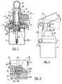
- the control unit as shown in the drawing comprises a relatively flat block shaped housing 1 having a cylindrical bore 2.
- a reservoir 3 for hydraulic liquid is secured against the downwardly facing end surface of the housing 1.
- a substantially cylindrical body 5 is journalled in the bore 2 with a normal or ample clearance with the interposition of an 0-ring 6 and is supported through a collar 7 on the upper end surface of the housing 1. The body 5 is locked therein in the axial direction relative to the housing 1 by a closing ring 9 engaging over the collar 7 and secured to the housing 1 by screws 8.
- the upper part 10 of the body 5 projecting beyond the upper surface of the housing 1 has a cylindrical bore 11 and constitutes the cylinder of a plunger pump, the plunger of which is indicated by the reference numeral 12.
- the end of the plunger 12 extending beyond the upper end of the cylinder 10 is coupled in known manner pivotally at 13 to a rocking piece 14 which is adapted for inserting therein an operating rod (not shown).
- This rocking piece is connected on the other hand to two pivot levers 15 which are in engagement with two pivot taps 16 provided in two opposite side walls of the housing.
- the rocking piece 14 may be moved upwardly and downwardly in the directions of the arrow (see Fig. 2) and therewith establish a pumping movement of the plunger 12.
- the lower part 17 of the body 5 has a central duct 18 connecting the bottom end of the cylinder bore 11 to the suction tube 19 extending into the reservoir 3.
- a ball shaped suction valve 20, closing toward the reservoir, is provided in the duct 18.
- a radial duct 21 is branched off the central duct 18 and opens in the peripheral surface of the said part 17.
- a pressure valve 22 in the embodiment of a ball valve is provided in the radial duct 21, opening radially outwardly against spring force.
- the end of the duct 21 opening in the peripheral surface of the part 17 furthermore is counterbored into a chamber in which a hollow cylindrical sealing element 23 is provided, manufactured of a suitable synthetic material and sealingly engaging the wall of the bore 2, also under the influence of the pressure in the duct 21.
- a second branch duct 24 opens at the lower end surface of the part 17 situated above the reservoir 3. Said branch contains a ball valve 25 which is adapted to open against spring force toward the reservoir 3 if the pressure in the duct 18 increases over its maximum.
- a cap 26 passing the plunger 12 is provided on the cylinder part 10. Said cap is coupled with the cylinder part 10 such that it is prevented to be rotated and has a lateral thumb-finger piece 27.
- the housing 1 has two connecting ports 26' and 27' respectively for the ends of the piston cylinder device to be operated, e.g. a double action hydraulic cylinder for tilting a truck cabin. Both ports have their axes contained in the same cross-sectional plane and the radial duct 21 in the part 17 acting as the control valve (see also Fig. 3).
- the control valve part 17 is further provided with two diametrally opposed flats 28 and 29 continuing in the axial direction in the chamber of the reservoir 3.
- the drawing shows the neutral position of the body 5, 17.
- the sealing element 23 faces the solid wall of the bore 2 and moving the pump plunger upwardly and downwardly will only result therein that hydraulic liquid, sucked from the reservoir through the valve 20, is returned to the reservoir through the overload valve 25.
- the body 5, 17 arrives in an operative position by rotating it from the position shown (Fig. 3) through an angle of about 45 ° to the right or to the left.
- the port 26' or 2T respectively will then face the hollow space of the sealing element 23 whereby the relative end of the piston cylinder device to be controlled is connected with the pressure side of the pump.
- the other port 27' or 26' respectively becomes connected with the flat 29 or 28 respectively whereby the liquid forced out at the relative end of the piston cylinder device is permitted to flow towards the reservoir.
Landscapes
- Engineering & Computer Science (AREA)
- Mechanical Engineering (AREA)
- Life Sciences & Earth Sciences (AREA)
- Geology (AREA)
- Structural Engineering (AREA)
- Chemical & Material Sciences (AREA)
- Combustion & Propulsion (AREA)
- Transportation (AREA)
- Details Of Reciprocating Pumps (AREA)
- Reciprocating Pumps (AREA)
Claims (1)
- Hydraulische Steuereinheit, insbesondere zum Betreiben einer hydraulischen Zylindervorrichtung, versehen mit einem Gehäuse (1) mit Verbindungsanschlüssen (26', 27') für Zufuhr- und Abfuhrleitungen zu bezw. von der zu betreibenden Zylindervorrichtung, einem Behälter (3) für hydraulische Flüssigkeit, einer mit letzterem verbundenen hydraulischen Plungerpumpe (11, 12) mit Saug- und Druckventilen (20, 22), wobei der Zylinder der Plungerpumpe aus einem Stück und koaxial in einem Körper gebildet ist, der in einer entsprechenden Bohrung (2) des Gehäuses drehbar verstellt werden kann, welcher Körper einen Drehschieber (5) bildet, welcher mindestens ein Druckkanal (21) aufweist, der einerseits mit der Pumpenzylinder verbunden ist und andererseits in der Umfangsfläche des genannten Ventilkörpers ausmündet und welcher zum weiteren mit mindestens einem Ablaufkanal (28, 29) versehen ist, der mit dem Behälter (3) dauernd verbunden ist, welcher Druckkanal (21) und Ablaufkanal (28, 29) wahlweise - und zwar in Abhängigkeit der Winkellage des Ventilkörpers innerhalb des Gehäuses (1) - mit je einer der genannten Verbindungsanschlüssen (26', 27') verbindbar sind, wobei der Druckkanal an seinem äusseren Ende eine erweiterte Bohrung aufweist, in der sich das Druckventil befindet und welche am äusseren Ende zum Teil abgeschlossen wird mittels eines perforierten Pfropfen (23) dadurch gekennzeichnet, dass der Ventilkörper (5, 10) eine zylindrische Form aufweist; dass der Pfropfen (23) in der Weise in der erweiterten Bohrung montiert ist, dass das äussere Ende desselben abdichtend in der Gehäusebohrung (2) anliegt, während der Druckkanal (21) in einem Kanal (18) mündet, der mit dem inneren Ende des Pumpenzylinders (10, 11) verbunden ist.
Applications Claiming Priority (2)
| Application Number | Priority Date | Filing Date | Title |
|---|---|---|---|
| NL8800590 | 1988-03-09 | ||
| NL8800590A NL8800590A (nl) | 1988-03-09 | 1988-03-09 | Hydraulische stuureenheid. |
Publications (2)
| Publication Number | Publication Date |
|---|---|
| EP0332279A1 EP0332279A1 (de) | 1989-09-13 |
| EP0332279B1 true EP0332279B1 (de) | 1990-07-18 |
Family
ID=19851913
Family Applications (1)
| Application Number | Title | Priority Date | Filing Date |
|---|---|---|---|
| EP19890200567 Expired EP0332279B1 (de) | 1988-03-09 | 1989-03-06 | Hydraulische Steuervorrichtung |
Country Status (3)
| Country | Link |
|---|---|
| EP (1) | EP0332279B1 (de) |
| DE (1) | DE68900004D1 (de) |
| NL (1) | NL8800590A (de) |
Families Citing this family (2)
| Publication number | Priority date | Publication date | Assignee | Title |
|---|---|---|---|---|
| NL9301030A (nl) * | 1993-06-14 | 1995-01-02 | Applied Power Inc | Hydraulische inrichting, bestaande uit een verdeelblok met positioneringsinrichting. |
| EP3486484A1 (de) * | 2017-11-20 | 2019-05-22 | Dana Motion Systems Italia S.R.L. | Kartuschenhandpumpe |
Family Cites Families (1)
| Publication number | Priority date | Publication date | Assignee | Title |
|---|---|---|---|---|
| NL22849C (de) * | 1900-01-01 |
-
1988
- 1988-03-09 NL NL8800590A patent/NL8800590A/nl not_active Application Discontinuation
-
1989
- 1989-03-06 EP EP19890200567 patent/EP0332279B1/de not_active Expired
- 1989-03-06 DE DE8989200567T patent/DE68900004D1/de not_active Expired - Lifetime
Also Published As
| Publication number | Publication date |
|---|---|
| DE68900004D1 (de) | 1990-08-23 |
| NL8800590A (nl) | 1989-10-02 |
| EP0332279A1 (de) | 1989-09-13 |
Similar Documents
| Publication | Publication Date | Title |
|---|---|---|
| US2182459A (en) | Valve housing and rotor | |
| US4491154A (en) | Double acting pilot valve | |
| US4924903A (en) | `Breech-block` tap for the supply of cold or hot water with ceramic sealing plates | |
| US5722297A (en) | Actuator system for gear shifting mechanisms of motor vehicles | |
| GB2446333A (en) | Control system for valve actuator | |
| EP0332279B1 (de) | Hydraulische Steuervorrichtung | |
| US4673172A (en) | Leveling valve with height limit | |
| CA3140934A1 (en) | Fully-integrated, fluid flow-control module designed for installation | |
| US4461320A (en) | Manually operable hydraulic control device with hydraulic position retention | |
| US20020148513A1 (en) | Valve unit with an overridable check valve and a fluid power drive fitted therewith | |
| US20190264714A1 (en) | Electro-hydraulic valve actuator having modular manifold with configurable redundancy | |
| IE43114B1 (en) | An hydraulic distributor | |
| US4351362A (en) | Rotary valve | |
| US4586538A (en) | Spindle valve for a tube system for liquids | |
| US2996047A (en) | Actuating means | |
| JP2007506914A (ja) | 液圧用アキュムレータ、特にピストン型アキュムレータ | |
| US6375154B1 (en) | Seat and holding valve | |
| US4421012A (en) | Control circuit throttling valve | |
| US7300035B2 (en) | Valve, actuator and control system therefor | |
| US3472283A (en) | Single-lever operated mixing valve | |
| US3554487A (en) | Rotary valve with pivotable seat | |
| US5011115A (en) | Self supporting plug for a double block and bleed plug valve | |
| USRE30517E (en) | Rotary valve | |
| JPS60104803A (ja) | 弁を制御するための油圧式作動装置 | |
| KR20050105971A (ko) | 액압장치 |
Legal Events
| Date | Code | Title | Description |
|---|---|---|---|
| PUAI | Public reference made under article 153(3) epc to a published international application that has entered the european phase |
Free format text: ORIGINAL CODE: 0009012 |
|
| AK | Designated contracting states |
Kind code of ref document: A1 Designated state(s): DE FR GB IT NL SE |
|
| 17P | Request for examination filed |
Effective date: 19890804 |
|
| 17Q | First examination report despatched |
Effective date: 19891110 |
|
| GRAA | (expected) grant |
Free format text: ORIGINAL CODE: 0009210 |
|
| AK | Designated contracting states |
Kind code of ref document: B1 Designated state(s): DE FR GB IT NL SE |
|
| REF | Corresponds to: |
Ref document number: 68900004 Country of ref document: DE Date of ref document: 19900823 |
|
| ITF | It: translation for a ep patent filed | ||
| ET | Fr: translation filed | ||
| ITTA | It: last paid annual fee | ||
| PLBE | No opposition filed within time limit |
Free format text: ORIGINAL CODE: 0009261 |
|
| STAA | Information on the status of an ep patent application or granted ep patent |
Free format text: STATUS: NO OPPOSITION FILED WITHIN TIME LIMIT |
|
| 26N | No opposition filed | ||
| PGFP | Annual fee paid to national office [announced via postgrant information from national office to epo] |
Ref country code: FR Payment date: 19940210 Year of fee payment: 6 |
|
| PGFP | Annual fee paid to national office [announced via postgrant information from national office to epo] |
Ref country code: SE Payment date: 19940215 Year of fee payment: 6 |
|
| PGFP | Annual fee paid to national office [announced via postgrant information from national office to epo] |
Ref country code: DE Payment date: 19940224 Year of fee payment: 6 |
|
| PGFP | Annual fee paid to national office [announced via postgrant information from national office to epo] |
Ref country code: GB Payment date: 19940225 Year of fee payment: 6 |
|
| PGFP | Annual fee paid to national office [announced via postgrant information from national office to epo] |
Ref country code: NL Payment date: 19940331 Year of fee payment: 6 |
|
| EAL | Se: european patent in force in sweden |
Ref document number: 89200567.9 |
|
| PG25 | Lapsed in a contracting state [announced via postgrant information from national office to epo] |
Ref country code: GB Effective date: 19950306 |
|
| PG25 | Lapsed in a contracting state [announced via postgrant information from national office to epo] |
Ref country code: SE Effective date: 19950307 |
|
| PG25 | Lapsed in a contracting state [announced via postgrant information from national office to epo] |
Ref country code: NL Effective date: 19951001 |
|
| GBPC | Gb: european patent ceased through non-payment of renewal fee |
Effective date: 19950306 |
|
| PG25 | Lapsed in a contracting state [announced via postgrant information from national office to epo] |
Ref country code: FR Free format text: LAPSE BECAUSE OF NON-PAYMENT OF DUE FEES Effective date: 19951130 |
|
| NLV4 | Nl: lapsed or anulled due to non-payment of the annual fee |
Effective date: 19951001 |
|
| PG25 | Lapsed in a contracting state [announced via postgrant information from national office to epo] |
Ref country code: DE Effective date: 19951201 |
|
| EUG | Se: european patent has lapsed |
Ref document number: 89200567.9 |
|
| REG | Reference to a national code |
Ref country code: FR Ref legal event code: ST |
|
| PG25 | Lapsed in a contracting state [announced via postgrant information from national office to epo] |
Ref country code: IT Free format text: LAPSE BECAUSE OF NON-PAYMENT OF DUE FEES;WARNING: LAPSES OF ITALIAN PATENTS WITH EFFECTIVE DATE BEFORE 2007 MAY HAVE OCCURRED AT ANY TIME BEFORE 2007. THE CORRECT EFFECTIVE DATE MAY BE DIFFERENT FROM THE ONE RECORDED. Effective date: 20050306 |