EP0332256A1 - Système graphique video muni d'un curseur graphique - Google Patents
Système graphique video muni d'un curseur graphique Download PDFInfo
- Publication number
- EP0332256A1 EP0332256A1 EP89200515A EP89200515A EP0332256A1 EP 0332256 A1 EP0332256 A1 EP 0332256A1 EP 89200515 A EP89200515 A EP 89200515A EP 89200515 A EP89200515 A EP 89200515A EP 0332256 A1 EP0332256 A1 EP 0332256A1
- Authority
- EP
- European Patent Office
- Prior art keywords
- identifier
- bits
- coordinates
- graphic
- image
- Prior art date
- Legal status (The legal status is an assumption and is not a legal conclusion. Google has not performed a legal analysis and makes no representation as to the accuracy of the status listed.)
- Granted
Links
- 238000011068 loading method Methods 0.000 claims description 6
- 239000003550 marker Substances 0.000 description 4
- 238000012800 visualization Methods 0.000 description 3
- 238000000034 method Methods 0.000 description 2
- 230000009466 transformation Effects 0.000 description 1
Images

Classifications
-
- G—PHYSICS
- G06—COMPUTING; CALCULATING OR COUNTING
- G06F—ELECTRIC DIGITAL DATA PROCESSING
- G06F3/00—Input arrangements for transferring data to be processed into a form capable of being handled by the computer; Output arrangements for transferring data from processing unit to output unit, e.g. interface arrangements
- G06F3/01—Input arrangements or combined input and output arrangements for interaction between user and computer
- G06F3/048—Interaction techniques based on graphical user interfaces [GUI]
- G06F3/0484—Interaction techniques based on graphical user interfaces [GUI] for the control of specific functions or operations, e.g. selecting or manipulating an object, an image or a displayed text element, setting a parameter value or selecting a range
- G06F3/04842—Selection of displayed objects or displayed text elements
-
- G—PHYSICS
- G06—COMPUTING; CALCULATING OR COUNTING
- G06T—IMAGE DATA PROCESSING OR GENERATION, IN GENERAL
- G06T1/00—General purpose image data processing
- G06T1/0007—Image acquisition
Definitions
- the invention relates to a video graphics system provided with a graphic cursor and a comparator which compares the coordinates X C , Y C of position of the graphic cursor with the coordinates X D , Y D of each element of each line, the elements being scanned in a frame scan, the graphic cursor interacting with the image delivered by the video graphics system.
- a video graphics system of this type is known from document EP 0 229 986. It describes a graphics system which stores image data and which is provided with a cursor with the aid of which it is possible to insert data into the image. For this, the cursor selects an area of the image where this transformation must take place and the system determines this area from the coordinates provided by the cursor.
- the purpose of this document is therefore to combine the information from the cursor path and the image data path.
- This device therefore does not make it possible to locate in its image characteristics which are specific to it, each image zone moreover having no identification code.
- the technical problem posed is to be able to identify portions of images using a graphic cursor whose mark is positioned on a desired area.
- the graphics system uses a buffer image memory which is alternately loaded at a given rate and then read at another rate. It operates on images formed of coded surfaces which can remain identical to themselves during several successive operations of loading then reading in memory before being in their turn renewed.
- the images made up of coded surfaces are synthetic images.
- Such images are, for example, those described in document EP 0 215 510, the content of which is incorporated in the present description by way of reference, where the coded surfaces originate from polygons.
- These are processed by the depth memory algorithm (Z-buffer in English) to view two-dimensional coded images where only the portions of polygons closest to an observation point appear.
- the coding is added description of the topology of each polygon, an identifier which is also stored in image memory.
- the controller can thus receive the entire identifier at the end of P read frames. This makes it possible to limit the size of the part of the image memory which stores the part of the identifier.
- the polygon can thus be identified and exploited either for its visualization or any other processing, the display of an index for example.
- the location of the coded surface is effected by moving a graphic marker on the surface of the screen of a display device using a box provided with a joystick activated by the user according to the usual known techniques. of the skilled person.
- the graphic controller thus has the coordinates X C , Y C of the position of the graphic coordinate system. It also has, using a counter / incrementer, the position X D , Y D of a current point moving on each picture element of each scan line whose corresponding data to be displayed are in the image memory.
- the position of the marker is determined and the identifier can then be stored in the identification memory after the expected number of frames and then processed by the controller as described above. The mark must remain within the same coded area for the expected number of frames for identification to be carried out.
- the graphic cursor will allow: - identify the positions of the marker on the screen and determine the coded surface on which it is positioned, - generate the benchmark itself, - to move the marker on the screen by the user.
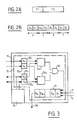
- FIG. 1A represents a video graphics system 10 which includes a graphics controller 11 provided with an identification circuit 12.
- the latter receives the coordinates (X C , Y C ) specific to the reference of the graphic cursor using a housing 13 activated by the user. These coordinates X C , Y C are used to display a reference mark 14 on the screen 19 of a display device 16.
- the graphic controller 11 determines the coordinates (X D , Y D ) of a current point on the screen 19 which corresponds to data in the image memory 15.
- the display device 16 operates in video mode according to scanning lines and frames.
- the computer 18 transmits to the image memory 15 both the data to be displayed on the screen (field 151 of the memory), as well as the N / P bit identifier part (field 152 of the memory).
- the part of the identifier is replaced by the following part.
- the data to be displayed on the screen are determined according to the algorithm used for determining the image, either by the computer 18 itself, or by a specialized circuit 181 itself managed by the computer 18. This circuit is for example that described in document EP 0 215 510.
- the identification circuit 12 When the identification circuit 12 has detected the identity of the coordinates (X C , Y C ) and the coordinates (X D , Y D ), the successive parts of the N / P identifier are stored (connection 9) in an identification memory 17 during the predetermined number of frames.
- the set of N bits of the identifier When the set of N bits of the identifier is received, it is then transmitted to the computer 18 which identifies the coded surface which relates to it.
- the computer 18 transmits to the image memory 15 information making it possible to represent on the screen of the display device 16 the images formed of coded surfaces.
- the display of an index on the screen or any other means makes it possible to draw the user's attention to the identification obtained.
- FIG. 1B shows the screen 19 of the display device 16 on which is represented a coded surface 20 and a graphic reference 14 associated with the housing 13.
- FIGS. 2A and 2B represent the coding mechanism of the identifier.
- a coded surface will be characterized by the data field F2 in the form for example of vertices or edges of polygons for example as described in document EP 0 215 510.
- this field F2 is associated with a second field F1 which constitutes an identifier of this coded surface.
- Such a field F1 can consist of 1 or more bits, for example 8 bits according to FIG. 2B.
- This field F1 of N bits will be able to be detected on a number P of frames.
- According to the speed desired to carry out this exchange it is possible to load / detect the 8 bits, bit after bit, on 8 successive loads / frames
- FIG. 3 represents the identification circuit 12 which makes it possible to process the identifier.
- the graphic controller 11 comprises the identification circuit 12 and a counter / incrementer 31. This supplies the coordinates X D , Y D of a current point on the screen to which data corresponds in the image memory.
- the circuit 12 also receives the coordinates X C , Y C introduced by the box handled by the user. These coordinates are stored in registers 321, 322, 331, 332.
- the data X C and X D on the one hand and Y C and Y D on the other hand are compared respectively in the comparators 341 and 342.
- the gate 35 delivers a signal which validates the introduction of the N / P bit part (connection 9) of the identifier I D into the identification memory 17.
- the mechanism is maintained during the desired number P of frames by a control signal C from the computer 18.
- the identifier When the identifier has been received in full, it is transmitted by connection 36 to the computer 18 (FIG. 1A) which displays an index determined on the display of the display device 16 or warns the user that the coded surface has been identified.
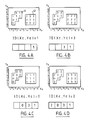
- FIGS. 4A, 4B, 4C, 4D represent the acquisition of an identifier on 4 successive frames.
- the identifier memory acquires the term "1" from the identifier.
- the identifier "2031" is then transmitted to the computer 18 for example to enable the image memory 18 to search for all the data relating to this coded surface 41 in order to operate the intervention desired by the user.
Abstract
Description
- L'invention concerne un système graphique vidéo muni d'un curseur graphique et d'un comparateur qui compare les coordonnées XC, YC de position du curseur graphique avec les coordonnées XD, YD de chaque élément de chaque ligne, les éléments étant explorés selon un balayage par trames, le curseur graphique interagissant avec l'image délivrée par le système graphique vidéo.
- Un système graphique vidéo de ce type est connu du document EP 0 229 986. Il décrit un système graphique qui stocke des données d'images et qui est muni d'un curseur à l'aide duquel il est possible d'insérer des données dans l'image. Pour cela le curseur sélectionne une zone de l'image où doit s'opérer cette transformation et le système détermine cette zone à partir des coordonnées fournies par le curseur.
- L'objet de ce document est donc de combiner les informations issues de la voie curseur et de la voie de données d'image.
- Ce dispositif ne permet donc pas de repérer dans une image des caractéristiques qui lui sont propres, chaque zone d'image n'ayant d'ailleurs pas de code d'identification.
- Le problème technique posé est de pouvoir identifier des portions d'images à l'aide d'un curseur graphique dont le repère est positionné sur une zone désirée.
- La solution à ce problème est que le système graphique vidéo comprend :
- une mémoire d'images qui au cours de chargements successifs stocke temporairement : - a) des paramètres numériques régulièrement explorés décrivant des surfaces codées relatives à des images à deux dimensions,
- b) et un identificateur à N bits, propre à chaque surface codée de sorte que les N bits soient successivement chargés en mémoire d'images par tranches de N/P bits au cours de P chargements successifs, avec P supérieur à 1, chaque chargement étant suivi d'une lecture de la mémoire d'images pour visualiser l'image selon les trames successives du balayage par trames,
- Le système graphique selon l'invention utilise une mémoire d'images tampon qui est alternativement chargée à un rythme donné puis lue à un autre rythme. Il opère sur des images formées de surfaces codées qui peuvent rester identiques à elles-mêmes au cours de plusieurs opérations successives de chargement puis de lecture en mémoire avant d'être à leur tour renouvelées.
- Préférentiellement les images constituées de surfaces codées sont des images de synthèse. De telles images sont par exemple celles décrites dans le document EP 0 215 510, dont le contenu est incorporé à la présente description à titre de référence, où les surfaces codées sont issues de polygones. Ceux-ci sont traités par l'algorithme de la mémoire de profondeur (Z-buffer en langue anglaise) pour visualiser en deux dimensions des images codées où n'apparaissent que les portions de polygones les plus rapprochées d'un point d'observation.
- Sur une telle image à deux dimensions il est souhaitable de pouvoir repérer les portions des surfaces codées visualisées et de les retrouver dans la mémoire d'images qui stocke toutes les données propres aux surfaces codées.
- Pour cela selon l'invention on adjoint, au codage descriptif de la topologie de chaque polygone, un identificateur qui est également stocké en mémoire d'image. Cet identificateur est un code de N bits qui est délivré par tranches avec les paramètres descriptifs des surfaces codées à chaque chargement en mémoire d'images :
. soit 1 bit d'identificateur durant P = N trames
. soit N/P bits d'identificateur durant P trames - Le contrôleur peut ainsi recevoir la totalité de l'identificateur à l'issue de P trames de lecture. Ceci permet de limiter la taille de la partie de la mémoire d'images qui stocke la partie de l'identificateur. Le polygone peut ainsi être identifié et exploité soit pour sa visualisation ou tout autre traitement, l'affichage d'un index par exemple.
- La localisation de la surface codée s'opère en déplaçant un repère graphique sur la surface de l'écran d'un dispositif de visualisation à l'aide d'un boîtier muni d'une manette activée par l'utilisateur selon les techniques habituelles connues de l'homme du métier.
- Le contrôleur graphique dispose ainsi des coordonnées XC,YC de la position du repère graphique. Il dispose également, à l'aide d'un compteur/incrémenteur, de la position XD, YD d'un point courant se déplaçant sur chaque élément d'image de chaque ligne de balayage dont les données à afficher correspondantes sont dans la mémoire d'image. Lorsque ces coordonnées sont identiques, la position du repère est déterminée et l'identificateur peut alors être stocké dans la mémoire d'identification après le nombre prévu de trames puis traité par le contrôleur comme décrit précédemment. Le repère doit rester à l'intérieur de la même surface codée au cours du nombre prévu de trames pour que l'identification soit effectuée.
- Le curseur graphique va permettre :
- d'identifier les positions du repère sur l'écran et de déterminer la surface codée sur laquelle il est positionné,
- de générer le repère lui-même,
- de déplacer le repère sur l'écran par l'utilisateur. - L'invention sera mieux comprise à l'aide des figures suivantes données à titre d'exemples non limitatifs qui représentent :
- figure 1A : un système de visualisation d'images comprenant un système graphique vidéo selon l'invention.
- figure 1B : une vue de la surface de l'écran de visualisation.
- figures 2A, 2B : une représentation du mécanisme de codage de l'identificateur.
- figure 3 : le circuit d'identification selon l'invention.
- figures 4A, 4B, 4C, 4D : une représentation de l'acquisition d'un identificateur sur 4 trames successives de balayage.
- La figure 1A représente un système graphique vidéo 10 qui comprend un contrôleur graphique 11 muni d'un circuit d'identification 12. Celui-ci reçoit les coordonnées (XC, YC) propres au repère du curseur graphique à l'aide d'un boîtier 13 activé par l'utilisateur. Ces coordonnées XC, YC servent à afficher un repère 14 sur l'écran 19 d'un dispositif de visualisation 16. Le contrôleur graphique 11 détermine les coordonnées (XD, YD) d'un point courant de l'écran 19 auquel correspond des données dans la mémoire d'images 15. Le dispositif de visualisation 16 opère en mode vidéo selon des lignes et des trames de balayage. Le calculateur 18 transmet à la mémoire d'image 15 à la fois les données à afficher sur l'écran (champ 15₁ de la mémoire), ainsi que la partie d'identificateur N/P bits (champ 15₂ de la mémoire). A chaque trame, la partie de l'identificateur est remplacée par la partie suivante. Les données à afficher sur l'écran sont déterminées selon l'algorithme mis en oeuvre pour la détermination de l'image, soit par le calculateur 18 lui-même, soit par un circuit spécialisé 18₁ lui-même géré par le calculateur 18. Ce circuit est par exemple celui décrit dans le document EP 0 215 510.
- Lorsque le circuit d'identification 12 a détecté l'identité des coordonnées (XC, YC) et des coordonnées (XD, YD), les parties successives de l'identificateur N/P sont stockées (connexion 9) dans une mémoire d'identification 17 au cours du nombre de trames prédéterminé. Lorsque l'ensemble des N bits de l'identificateur est reçu, celui-ci est alors transmis au calculateur 18 qui identifie la surface codée qui s'y rapporte. Le calculateur 18 transmet à la mémoire d'image 15 des informations permettant de représenter sur l'écran du dispositif de visualisation 16 les images formées de surfaces codées. L'affichage d'un index sur l'écran ou tout autre moyen permet d'attirer l'attention de l'utilisateur sur l'identification obtenue.
- La figure 1B représente l'écran 19 du dispositif de visualisation 16 sur lequel est représenté une surface codée 20 et un repère graphique 14 associé au boîtier 13.
- Les figures 2A et 2B représentent le mécanisme de codage de l'identificateur. Une surface codée va être caractérisée par le champ de données F2 sous la forme par exemple de sommets ou d'arêtes de polygones par exemple tel que décrit dans le document EP 0 215 510. Selon l'invention on associe à ce champ F2 un second champ F1 qui constitue un identificateur de cette surface codée. Un tel champ F1 peut être constitué de 1 ou plusieurs bits par exemple 8 bits selon la figure 2B. Ce champ F1 de N bits va pouvoir être détecté sur un nombre P de trames. Ainsi sur l'exemple avec N=8 bits il est possible d'effectuer 4 chargements en mémoire d'images puis de détecter sur quatre trames (P=4) quatre fois 2 bits d'identificateur. Selon la rapidité désirée pour effectuer cet échange il est possible de charger/détecter les 8 bits, bit après bit, sur 8 chargements/trames successifs, ou toute autre combinaison.
- La figure 3 représente le circuit d'identification 12 qui permet de traiter l'identificateur. Le contrôleur graphique 11 comprend le circuit d'identification 12 et un compteur/incrémenteur 31. Celui-ci fournit les coordonnées XD, YD d'un point courant de l'écran auquel correspond des données dans la mémoire d'image. Le circuit 12 reçoit également les coordonnées XC, YC introduites par le boîtier manipulé par l'utilisateur. Ces coordonnées sont stockées dans des registres 32₁, 32₂, 33₁, 33₂. Les données XC et XD d'une part et YC et YD d'autre part sont comparées respectivement dans les comparateurs 34₁ et 34₂. Lorsqu'il y a identité deux à deux, la porte 35 délivre un signal qui valide l'introduction de la partie N/P bits (connexion 9) de l'identificateur ID dans la mémoire d'identification 17. Le mécanisme est maintenu durant le nombre désiré P de trames par un signal de contrôle C issu du calculateur 18. Lorsque l'identificateur a été reçu en totalité il est transmis par la connexion 36 vers le calculateur 18 (figure 1A) qui affiche un index déterminé sur l'écran du dispositif de visualisation 16 ou prévient l'utilisateur que la surface codée a été identifiée.
- Les figures 4A, 4B, 4C, 4D représentent l'acquisition d'un identificateur sur 4 trames successives. Soient une surface codée 41 à identifier et une surface codée 42 qui ne fait pas l'objet d'une identification. Le curseur graphique est par exemple positionné en XC=2 et YC=3. Lorsque le compteur/incrémenteur délivre les coordonnées XD=2 et YD=3 il y a alors identité. Soit un identificateur codé sur 8 bits représenté sur les figures en notation décimale pour faciliter la représentation. A la première trame la mémoire d'identificateur acquiert le terme "1" de l'identificateur. Puis au cours des 2ème, 3ème et 4ème trame elle acquiert respectivement les termes "3" puis "0" puis "2" pour disposer à l'issue des 4 trames de l'identificateur complet "2031". L'identificateur de l'autre surface codée 42 a lui aussi évolué mais n'a pas donné lieu à identification.
- L'identificateur "2031" est alors transmis au calculateur 18 par exemple pour permettre de rechercher dans la mémoire d'images 18 l'ensemble des données relatives à cette surface codée 41 afin d'opérer l'intervention désirée par l'utilisateur.
Claims (3)
- une mémoire d'images qui au cours de chargements successifs stocke temporairement :
a) des paramètres numériques régulièrement explorés décrivant des surfaces codées, relatives à des images à deux dimensions,
b) et un identificateur à N bits, propre à chaque surface codée de sorte que les N bits soient successivement chargés en mémoire d'images par tranches de N/P bits au cours de P chargements successifs, avec P supérieur à 1, chaque chargement étant suivi d'une lecture de la mémoire d'images pour visualiser l'image selon les trames successives du balayage par trames,
- et un contrôleur graphique qui reçoit les tranches de N/P bits à chaque trame de lecture et reconstitue l'identificateur à N bits d'une surface codée après P trames de lecture successives, le contrôleur comprenant un circuit d'identification muni du comparateur et d'une mémoire d'identification qui stocke l'identificateur en cumulant les tranches de N/P bits au rythme de la lecture lorsque le comparateur a détecté l'identité des coordonnées (XC, YC) et des coordonnées (XD, YD), l'identificateur complet stocké étant utilisé par le contrôleur graphique vidéo pour identifier la surface codée concernée par cet identificateur.
Applications Claiming Priority (2)
| Application Number | Priority Date | Filing Date | Title |
|---|---|---|---|
| FR8802941A FR2628553B1 (fr) | 1988-03-08 | 1988-03-08 | Systeme graphique video muni d'un curseur graphique |
| FR8802941 | 1988-03-08 |
Publications (2)
| Publication Number | Publication Date |
|---|---|
| EP0332256A1 true EP0332256A1 (fr) | 1989-09-13 |
| EP0332256B1 EP0332256B1 (fr) | 1993-06-16 |
Family
ID=9364024
Family Applications (1)
| Application Number | Title | Priority Date | Filing Date |
|---|---|---|---|
| EP89200515A Expired - Lifetime EP0332256B1 (fr) | 1988-03-08 | 1989-03-02 | Système graphique video muni d'un curseur graphique |
Country Status (5)
| Country | Link |
|---|---|
| US (1) | US4977518A (fr) |
| EP (1) | EP0332256B1 (fr) |
| JP (1) | JPH07104663B2 (fr) |
| DE (1) | DE68907085T2 (fr) |
| FR (1) | FR2628553B1 (fr) |
Cited By (1)
| Publication number | Priority date | Publication date | Assignee | Title |
|---|---|---|---|---|
| FR2683648A1 (fr) * | 1991-11-12 | 1993-05-14 | Apple Computer | Procede de choix d'objets dans une sequence d'images mobiles et piste d'essai de reussite correspondante. |
Families Citing this family (5)
| Publication number | Priority date | Publication date | Assignee | Title |
|---|---|---|---|---|
| JPH0797413B2 (ja) * | 1991-05-16 | 1995-10-18 | インターナショナル・ビジネス・マシーンズ・コーポレイション | グラフィックス・システムにおけるピック方法および装置 |
| WO1994027240A1 (fr) * | 1993-05-10 | 1994-11-24 | Apple Computer, Inc. | Systeme graphique d'ordinateur comprenant une memoire de profondeur multicouche haute performance |
| US5748946A (en) * | 1995-02-17 | 1998-05-05 | International Business Machines Corporation | Method and apparatus for improved graphics picking using auxiliary buffer information |
| US5727141A (en) * | 1995-05-05 | 1998-03-10 | Apple Computer, Inc. | Method and apparatus for identifying user-selectable regions within multiple display frames |
| GB2307815A (en) * | 1995-11-29 | 1997-06-04 | Ibm | An image processing system using shared memory |
Citations (3)
| Publication number | Priority date | Publication date | Assignee | Title |
|---|---|---|---|---|
| GB1387407A (en) * | 1971-04-30 | 1975-03-19 | Image Analysing Computers Ltd | Visual feature classification |
| FR2530047A1 (fr) * | 1982-07-07 | 1984-01-13 | Roux Roger | Saisie informatique associee a une tablette graphique |
| US4646076A (en) * | 1983-04-27 | 1987-02-24 | Sperry Corporation | Method and apparatus for high speed graphics fill |
Family Cites Families (7)
| Publication number | Priority date | Publication date | Assignee | Title |
|---|---|---|---|---|
| JPS59132070A (ja) * | 1983-01-18 | 1984-07-30 | Mitsubishi Electric Corp | アレイ演算用デ−タ処理装置 |
| JPS6061790A (ja) * | 1983-09-16 | 1985-04-09 | 株式会社日立製作所 | 表示用制御回路 |
| CA1250064A (fr) * | 1985-03-29 | 1989-02-14 | Kenichi Anjyo | Methode de construction d'un modele polyhedre tridimensionnel |
| US4782463A (en) * | 1985-09-12 | 1988-11-01 | International Business Machines Corp. | Method for generating display screens for a set of application programs by calling screen management subroutines |
| US4829455A (en) * | 1986-04-11 | 1989-05-09 | Quantel Limited | Graphics system for video and printed images |
| US4930092A (en) * | 1987-01-20 | 1990-05-29 | Auto-Trol Technology Corporation | Polygon display apparatus and method |
| JPS63254513A (ja) * | 1987-04-13 | 1988-10-21 | Toshiba Corp | 画面表示方法 |
-
1988
- 1988-03-08 FR FR8802941A patent/FR2628553B1/fr not_active Expired - Lifetime
-
1989
- 1989-03-02 EP EP89200515A patent/EP0332256B1/fr not_active Expired - Lifetime
- 1989-03-02 US US07/318,085 patent/US4977518A/en not_active Expired - Fee Related
- 1989-03-02 DE DE89200515T patent/DE68907085T2/de not_active Expired - Fee Related
- 1989-03-07 JP JP1053048A patent/JPH07104663B2/ja not_active Expired - Lifetime
Patent Citations (3)
| Publication number | Priority date | Publication date | Assignee | Title |
|---|---|---|---|---|
| GB1387407A (en) * | 1971-04-30 | 1975-03-19 | Image Analysing Computers Ltd | Visual feature classification |
| FR2530047A1 (fr) * | 1982-07-07 | 1984-01-13 | Roux Roger | Saisie informatique associee a une tablette graphique |
| US4646076A (en) * | 1983-04-27 | 1987-02-24 | Sperry Corporation | Method and apparatus for high speed graphics fill |
Non-Patent Citations (2)
| Title |
|---|
| ELECTRONIQUE, no. 265, mars 1979, pages 47-49, Paris, FR: D. BRANELLEC: "Le traitement d'image en couleurs" * |
| IBM TECHNICAL DISCLOSURE BULLETIN, vol. 21, no. 8, janvier 1979, page 3284, New York, US; W.F. BEAUSOLEIL et al.: "Object identification and local highlighting on displays" * |
Cited By (5)
| Publication number | Priority date | Publication date | Assignee | Title |
|---|---|---|---|---|
| FR2683648A1 (fr) * | 1991-11-12 | 1993-05-14 | Apple Computer | Procede de choix d'objets dans une sequence d'images mobiles et piste d'essai de reussite correspondante. |
| US6219048B1 (en) | 1991-11-12 | 2001-04-17 | Apple Computer, Inc. | Object selection using hit test tracks |
| US6295055B1 (en) | 1991-11-12 | 2001-09-25 | Apple Computer, Inc. | Object selection using hit test tracks |
| US7043694B2 (en) | 1991-11-12 | 2006-05-09 | Apple Computer, Inc. | Object selection using hit test tracks |
| US7281212B2 (en) | 1991-11-12 | 2007-10-09 | Apple Inc. | Object selection using hit test tracks |
Also Published As
| Publication number | Publication date |
|---|---|
| US4977518A (en) | 1990-12-11 |
| EP0332256B1 (fr) | 1993-06-16 |
| JPH07104663B2 (ja) | 1995-11-13 |
| FR2628553B1 (fr) | 1990-11-09 |
| DE68907085T2 (de) | 1994-01-05 |
| DE68907085D1 (de) | 1993-07-22 |
| JPH027094A (ja) | 1990-01-11 |
| FR2628553A1 (fr) | 1989-09-15 |
Similar Documents
| Publication | Publication Date | Title |
|---|---|---|
| US6664948B2 (en) | Tracking pointing device motion using a single buffer for cross and auto correlation determination | |
| US6661838B2 (en) | Image processing apparatus for detecting changes of an image signal and image processing method therefor | |
| KR101286148B1 (ko) | 화상파일 생성장치, 화상처리장치, 화상파일 생성방법, 및 화상처리방법 | |
| US7298364B2 (en) | Display device | |
| EP0881592A3 (fr) | Sélection de text/image dans des images de documents | |
| JP4626775B2 (ja) | 情報処理装置及び情報処理プログラム | |
| CN110290426B (zh) | 展示资源的方法、装置、设备及存储介质 | |
| CN109948525A (zh) | 拍照处理方法、装置、移动终端以及存储介质 | |
| JP2001005582A (ja) | 画像ベースのデータを描画するシステムおよび方法 | |
| CN111461070B (zh) | 文本识别方法、装置、电子设备及存储介质 | |
| EP0332256B1 (fr) | Système graphique video muni d'un curseur graphique | |
| CN112509027A (zh) | 重定位方法、机器人及计算机可读存储介质 | |
| CN109068063B (zh) | 一种三维图像数据的处理、显示方法、装置及移动终端 | |
| WO2022062343A1 (fr) | Dispositif, système, procédé de détection aveugle d'altération par retrait d'image et support de stockage | |
| CN110211022A (zh) | 一种图像处理方法、装置及电子设备 | |
| JP2020091745A (ja) | 画像撮像支援装置及び画像撮像支援方法 | |
| US7302081B2 (en) | Method for detecting new objects in an illuminated scene | |
| US20110187721A1 (en) | Line drawing processing apparatus, storage medium storing a computer-readable program, and line drawing processing method | |
| US9196068B2 (en) | Projector system, and method for drawings | |
| EP2169622A1 (fr) | Appareil et procédé d'analyse d'image | |
| EP3239826A1 (fr) | Procede de copie d'ecran | |
| CN112163554B (zh) | 获取视频中的标记掩模的方法和装置 | |
| JP2008123090A (ja) | カメラポインタ装置、ラベリング方法及びプログラム | |
| JPH0140376B2 (fr) | ||
| CN116798056B (zh) | 表格图像定位方法、装置、设备、计算机可读存储介质 |
Legal Events
| Date | Code | Title | Description |
|---|---|---|---|
| PUAI | Public reference made under article 153(3) epc to a published international application that has entered the european phase |
Free format text: ORIGINAL CODE: 0009012 |
|
| AK | Designated contracting states |
Kind code of ref document: A1 Designated state(s): DE FR GB SE |
|
| RAP1 | Party data changed (applicant data changed or rights of an application transferred) |
Owner name: N.V. PHILIPS' GLOEILAMPENFABRIEKEN Owner name: LABORATOIRES D'ELECTRONIQUE PHILIPS |
|
| 17P | Request for examination filed |
Effective date: 19900308 |
|
| 17Q | First examination report despatched |
Effective date: 19920611 |
|
| GRAA | (expected) grant |
Free format text: ORIGINAL CODE: 0009210 |
|
| AK | Designated contracting states |
Kind code of ref document: B1 Designated state(s): DE FR GB SE |
|
| PG25 | Lapsed in a contracting state [announced via postgrant information from national office to epo] |
Ref country code: SE Effective date: 19930616 |
|
| REF | Corresponds to: |
Ref document number: 68907085 Country of ref document: DE Date of ref document: 19930722 |
|
| GBT | Gb: translation of ep patent filed (gb section 77(6)(a)/1977) |
Effective date: 19930913 |
|
| PLBE | No opposition filed within time limit |
Free format text: ORIGINAL CODE: 0009261 |
|
| STAA | Information on the status of an ep patent application or granted ep patent |
Free format text: STATUS: NO OPPOSITION FILED WITHIN TIME LIMIT |
|
| 26N | No opposition filed | ||
| REG | Reference to a national code |
Ref country code: FR Ref legal event code: CJ Ref country code: FR Ref legal event code: CD |
|
| REG | Reference to a national code |
Ref country code: FR Ref legal event code: TP |
|
| PGFP | Annual fee paid to national office [announced via postgrant information from national office to epo] |
Ref country code: FR Payment date: 20010326 Year of fee payment: 13 |
|
| PGFP | Annual fee paid to national office [announced via postgrant information from national office to epo] |
Ref country code: GB Payment date: 20010330 Year of fee payment: 13 |
|
| PGFP | Annual fee paid to national office [announced via postgrant information from national office to epo] |
Ref country code: DE Payment date: 20010516 Year of fee payment: 13 |
|
| REG | Reference to a national code |
Ref country code: GB Ref legal event code: IF02 |
|
| PG25 | Lapsed in a contracting state [announced via postgrant information from national office to epo] |
Ref country code: GB Free format text: LAPSE BECAUSE OF NON-PAYMENT OF DUE FEES Effective date: 20020302 |
|
| PG25 | Lapsed in a contracting state [announced via postgrant information from national office to epo] |
Ref country code: DE Free format text: LAPSE BECAUSE OF NON-PAYMENT OF DUE FEES Effective date: 20021001 |
|
| GBPC | Gb: european patent ceased through non-payment of renewal fee |
Effective date: 20020302 |
|
| PG25 | Lapsed in a contracting state [announced via postgrant information from national office to epo] |
Ref country code: FR Free format text: LAPSE BECAUSE OF NON-PAYMENT OF DUE FEES Effective date: 20021129 |
|
| REG | Reference to a national code |
Ref country code: FR Ref legal event code: ST |