EP0332048A2 - Multiple coil eddy current probe and method of flaw detection - Google Patents
Multiple coil eddy current probe and method of flaw detection Download PDFInfo
- Publication number
- EP0332048A2 EP0332048A2 EP89103630A EP89103630A EP0332048A2 EP 0332048 A2 EP0332048 A2 EP 0332048A2 EP 89103630 A EP89103630 A EP 89103630A EP 89103630 A EP89103630 A EP 89103630A EP 0332048 A2 EP0332048 A2 EP 0332048A2
- Authority
- EP
- European Patent Office
- Prior art keywords
- coils
- coil
- current
- wall
- eddy current
- Prior art date
- Legal status (The legal status is an assumption and is not a legal conclusion. Google has not performed a legal analysis and makes no representation as to the accuracy of the status listed.)
- Withdrawn
Links
Images


Classifications
-
- G—PHYSICS
- G01—MEASURING; TESTING
- G01N—INVESTIGATING OR ANALYSING MATERIALS BY DETERMINING THEIR CHEMICAL OR PHYSICAL PROPERTIES
- G01N27/00—Investigating or analysing materials by the use of electric, electrochemical, or magnetic means
- G01N27/72—Investigating or analysing materials by the use of electric, electrochemical, or magnetic means by investigating magnetic variables
- G01N27/82—Investigating or analysing materials by the use of electric, electrochemical, or magnetic means by investigating magnetic variables for investigating the presence of flaws
- G01N27/90—Investigating or analysing materials by the use of electric, electrochemical, or magnetic means by investigating magnetic variables for investigating the presence of flaws using eddy currents
- G01N27/9046—Investigating or analysing materials by the use of electric, electrochemical, or magnetic means by investigating magnetic variables for investigating the presence of flaws using eddy currents by analysing electrical signals
-
- G—PHYSICS
- G01—MEASURING; TESTING
- G01N—INVESTIGATING OR ANALYSING MATERIALS BY DETERMINING THEIR CHEMICAL OR PHYSICAL PROPERTIES
- G01N27/00—Investigating or analysing materials by the use of electric, electrochemical, or magnetic means
- G01N27/72—Investigating or analysing materials by the use of electric, electrochemical, or magnetic means by investigating magnetic variables
- G01N27/82—Investigating or analysing materials by the use of electric, electrochemical, or magnetic means by investigating magnetic variables for investigating the presence of flaws
- G01N27/90—Investigating or analysing materials by the use of electric, electrochemical, or magnetic means by investigating magnetic variables for investigating the presence of flaws using eddy currents
- G01N27/904—Investigating or analysing materials by the use of electric, electrochemical, or magnetic means by investigating magnetic variables for investigating the presence of flaws using eddy currents with two or more sensors
Definitions
- This invention generally relates to an eddy current probe system and method, and is specifically concerned with an improved probe system having a plurality of concentrically-disposed coils for simultaneously detecting different types of flaws or discontinuities at different depths within a wall of, for example, an Inconel* tube.
- Eddy current probes for inspecting the walls of metallic conduits are known in the prior art. Such probes are particularly useful in inspecting the Inconel tubes used as heat exchangers in nuclear steam generators for flaws caused by corrosion or fretting.
- these eddy current probes comprise a coil mounted in a probe head that is slidably movable within the interior of the tube being inspected, and electrically connected to a current generator which conducts an alternating current through the coil as it is moved.
- the current generator is typically capable of generating alternating currents having frequencies of between 10 kHz and 1 MHz.
- An impedance detecting circuit which may take the form of an inductive bridge, is also connected across the leads of the coil.
- the alternating current conducted through the coil excites it into generating a pulsating magnetic field whose magnitude and polarity changes in accordance with the frequency of the current.
- the changing magnetic flux emanating from the coil induces eddy currents in a portion of the wall.
- the particular voltage, amperage and direction of the eddy currents produced are dependent in part upon the specific impedance of the portion of the wall that conducts the eddy current. Because the direction of flow of the eddy currents generated by the coil is opposite to the current flowing through the probe coil, the magnetic field created by the eddy currents creates an impedance in the probe coil.
- the impedance experienced by the eddy currents is in turn dependent upon the resistance these currents encounter as they circulate through the wall. Since flaws in the metal wall (such as cracks, pits, or regions of local thinning) create regions of higher resistances at the flaw locations, eddy current probes may be used to locate flaws by constantly monitoring the impedances of the coils as the probe coils are moved along the walls of the tube. Sharp changes in impedance over localized areas would indicate the existence of cracks or pits or other relatively small area flaws, whereas gradual changes in impedance over a broad region of the conduit might indicate large-area flaws such as a grain change in the metal, an area of material creep, or a thinned wall region.
- Such prior art eddy current probes utilize either a single bobbin type coil whose axis of rotation is parallel with the longitudinal axis of the conduit being inspected (and which is operated in an "absolute” mode), or a pair of bobbin coils having the same radius which are spaced apart from one another (which are operated in a “differential” mode).
- the probe head containing either the single or the double coil is moved within the interior of the tube along its longitudinal axis.
- "pancake-type" probe coil configurations have come in to use.
- the axis of rotation of the windings of a relatively flat coil is disposed along the radius of the conduit, and the coil is used to scan the inner wall of the conduit by moving it both radially and longitudinally, thereby imparting a helical motion to the coil.
- Such pancake-type coils are capable of more accurately locating the precise point where some types of flaws reside in the conduit wall. Both configurations have been successfully used in hostile environments where direct inspection of tubing is impossible, such as the walls of the approximately 40 miles of Inconel tubes used as heat exchangers in nuclear steam generators.
- an eddy current probe system which is capable of accurately and reliably plotting all types of flaws at all different depths within the walls of a small diametered metallic tube with only a single rapid scan.
- an eddy current probe system would provide better resolution than any prior art probe system or combination of any such systems.
- the eddy current probe system should be extremely versatile, and capable of instantaneously adjusting its pulsating magnetic fields for maximum coupling with the flaw areas detected so as to afford maximum resolution under a broad range of conditions.
- the invention is an improved eddy current probe for simultaneously detecting different types of flaws at different depths.
- the improved probe includes a current generator for generating alternating currents of substantially different frequencies, and a plurality of concentrically arranged coils, each of which separately communicates with the current generating means and each of which conducts an alternating current of substantially different frequency for detecting different types of flaws at different depths within the metallic wall.
- a magnetic shielding material is disposed between the edges of adjacent coils for preventing cross-talk between each coil and the pulsating magnetic fields generated by adjacent coils.
- the probe system further includes an impedance detector circuit for providing an electrical output representative of the relative impedance of the respective coils. Both the current generator means and impedance detector circuit may be parts of a commercially available eddy current testing device.
- the highest frequency alternating current is conducted through the coil having the smallest diameter, whereas the lowest frequency alternating current is conducted through the coil having the largest diameter, for two reasons.
- the application of a relatively low frequency alternating current to the largest diameter coil insures that at least one of the pulsating fields emanating from the coils will penetrate far enough into the tube wall and resolve flaws located on the exterior tube surface, such as areas of grain change, creep and wall thinning due to corrosion, fretting or mechanical scratching.
- the probe head of the preferred embodiment includes three concentrically disposed coils of progressively larger diameter which may conduct frequencies as high as 1.0 MHz and as low as 30 kHz.
- the inner coil preferably initially conducts an alternating current of approximately 500 kHz, the middle coil a current of approximately 250 kHz, and the outer coil a current of approximately 50 kHz.
- the improved eddy current probe system may include a computer connected to both the impedance detector circuit and the current generator for adjusting and multiplexing the frequencies of the alternating current conductedhrough the coils of the probe head as the head is moved along a selected portion of the metallic wall and comparing the resulting amounts of coil impedance detected in order to minimize the impedance of each coil and hence to maximize the flaw-detecting resolution of the probe head.
- the computer receives and stores the value of the impedance of each coil as the probe is helically moved around the interior of the tube wall.
- the computer incrementally adjusts the frequencies of these currents either upwardly or downwardly, and compares the values of the impedances of each coil associated with both the old frequency and the new incrementally adjusted frequency.
- the computer makes subsequent incremental adjustments to the alternating current frequencies based on the resulting comparisons for the purpose of arriving at the minimum impedance values achievable with the coils.
- the resolution of the probe head, as a whole is maximized.
- the probe system of the invention obviates the need for multiple scans of the tube wall being inspected.
- the concentric arrangement of the coils locates flaws and other discontinuities in a faster and more accurate manner than would a colinear or other multiple arrangement of such coils due to the clear reference point provided by the centrally disposed, small diameter coil which preferably transmits a sharply focused, high-frequency pulsating magnetic field.
- the near-instantaneous, impedance minimizing adjustments of the frequencies of the alternating currents conducted through the various diametered coils insured that the resolution of the probe head will be maximized at every point of inspection without any significant sacrifice in scanning time.
- the eddy current probe system 1 of the invention is particularly well adapted for inspecting the walls 2 of an Inconel tube 3 of the type used in nuclear steam generators for different types of flaws at different depths within the walls 2, such as cracks 4 (both axially and radially aligned), pits 5, and broader sections 6 of the tube wall which have been subjected to creep or grain change, or thinned by corrosion, fretting or mechanical abrasion.
- the probe system 1 includes a probe head 8 which emanates a magnetic field 9 generated by a multiplicity of concentrically-arranged coils, each of which conducts a different frequency alternating current.
- the probe head 8 is mechanically mounted in a probe body (not shown) that is moved along a helical path by a drive unit 8.5 that includes an electric drive motor coupled to an optical encoder.
- the drive unit 8.5 is selectively actuated by a switching circuit 9.5 that is in turn connected to a power source (not shown).
- the probe head 8 is electrically connected via a cable to eddy current circuitry generally designated at 10.
- This eddy current circuitry 10 includes a computer-compatible frequency multiplexer 11 which, in the preferred embodiment, is a model MIZ 18 manufactured by ZETEC, Inc., located in Isaquah, Washington, USA.
- the frequency multiplexer 11 is connected to a computer 12 which is programmed to adjust the frequencies of the currents conducted through the coils of the probe head 8 to optimize resolution whenever an impedance change indicative of a flaw or other discontinuity is detected.
- the computer 12 is preferably a Model HP 9836 and an IEEE 488 interface circuit manufactured by Hewlett-Packard located in Palo Alto, California, USA, modified by a Zetec DDA-4 processing package.
- the output of the computer 12 is connected to a cathode ray tube (CRT) 13 which displays, through selected computer graphics, the impedance changes experienced by the coils within the probe head 8 as they are helically moved around the inner surface of the wall 2 of the Inconel tube 3.
- the frequency multiplexer 11 includes a current generator 14 for generating a multiplicity of alternating currents.
- the leads of the concentrically arranged coils within the probe head 8 are connected to the current generator 14 by way of a switching circuit 15. This switching circuit 15 acts to selectively conduct the same current through one or more of the concentrically arranged coils in the probe head 8 when the overall resolution of the system 1 would be enhanced by such an interconnection.
- the current generator 14 is connected to and controlled by a frequency adjusting and timing circuit 16.
- the circuit 16 is capable of not only changing the frequency of the currents conducted through each of the concentrically arranged coils of the probe head 8, but also of multiplexing a sequence of different-frequency currents through each of the coils.
- the frequency multiplexer 11 includes an impedance measuring circuit 17 which may be an inductive bridge connected to the current generator 14 for measuring changes in impedance experienced by the concentrically arranged coils in the probe head 8 as they are helically moved along the tube 3.
- *Delrin is a registered U.S. trademark belonging to E.I. DuPont De Nemours and Company of Wilmington, Delaware, USA.
- the probe head 8 is mounted within a probe body, such as the Delrin* probe carrier of the combined ultrasonic and eddy current inspection probe described and claimed in co-pending U.S. Patent Application Serial No. 079,860, filed July 30, 1987, by Thomas Arzenti and assigned to the Westinghouse Electric Corporation, the entire specification of which is incorporated herein by reference.
- the probe carrier of the aforementioned probe helically moves the probe head 8 in wiping engagement with the inner surface of the wall 2 of an Inconel tube 3 to scan the same.
- such helical motion includes an axial component along the longitudinal axis Y of the tube 3, as well as an angular component w along the radium r of the tube 3.
- the probe head 8 As will be described in more detail hereinafter, as the probe head 8 is scanningly moved throughout the inner surface of the tube wall 2, different frequencies of alternating current are conducted through different probe coils so as to generate a plurality of different shaped pulsating magnetic fields. At least one of these coils generates a field that penetrates completely through the wall 2 of the tube 3 so that exterior surface flaws such as the thinned portion 6 of the tube may be detected. At least one of the coils generates a magnetic field which interacts substantially with the inner surface of the wall 2 of the tube 3 so that interior surface flaws such as pit 5 which exist predominantly in the interior portion of the wall 2. Finally, at least one of the coils in the probe head 8 generates a pulsating
- each one of the ten scans illustrated on the CRT screen 13 includes a different-colored output for each of the coils in the probe head 8.
- three coils are used in the probe head 8, although many more of such coils may be used if desired.
- the output of the small-frequency coil is illustrated by a small-dashed line, while the output of the medium and low frequency coils are represented by large-dashed and solid lines, respectively.
- the small, medium and large diametered coils are initially operated at 500, 250 and 50 kHz respectively, and are adjusted to maximize the resolution of the probe system 1 when an impedance change indicative of a flaw is detected.
- the exterior of the probe head 8 is formed by a casing 19 preferably fabricated from a plastic material such as Delrin.
- the casing 19 includes a ring-shaped side wall 20 for retaining the coils and the probe head 8, as well as a circular back plate 21 having a centrally disposed mounting lug 22 projecting therefrom.
- the ring-shaped side wall 20, the circular back plate 21 and mounting lug 22 are all integrally formed.
- the interior of the probe head 8 includes outer, middle and inner shield walls 23, 25 and 27, as well as outer, middle and inner probe coils 32, 34, 36.
- Each of the shield walls 23, 25 and 27 is formed from a ring 29 of material that is very high in magnetic permeability which is closely circumscribed by a ring 30 of material which is somewhat lower in magnetic permeability but which has higher saturation characteristics than the ring 29 that it circumscribes.
- the inner ring 29 of each shield is formed from Netic* foil.
- the ring-shaped shield walls 23, 25 and 27 insulate each of the coils 32, 34 and 36 from the pulsating magnetic fields created by the coils adjacent thereto by providing a low reluctance path that diverts potentially interfering magnetic fields from the coil surrounded thereby. Such shielding in turn prevents inter coil cross-talk during the operation of the probe system 1.
- each of the coils 32, 34 and 36 includes a pair of leads 33a, 33b, 35a, 35b and 37a, 37b which are ultimately connected to the frequency multiplexer 11 by way of a cable as indicated in Figure 1.
- a ferrite focusing core 39 is centrally disposed within the inner coil 36 in order to both focus and intensify the pulsating magnetic field generated thereby, thereby advantageously creating a reference point for inferring the location of the surrounding coils 32 and 34. While a total of three coils are shown in the preferred embodiment, a greater number of coils could be used if desired.
- both the outer, middle and inner probe coils 32, 34 and 36 are formed from about thirty windings of copper wire.
- these windings are formed from very thin wire.
- the coil windings may also be formed from state-of-the-art printed circuit board techniques. Probe head coils formed by way of this latter method are advantageously flatter than coils formed by bobbin-like windings of copper wire.
- the front face of the probe head 8 is coated with a thin layer of Delrin or some other self-lubricating plastic material both to protect the delicate coil windings, and to minimize friction as the probe head 8 helically rides along the inner surface of the tube wall 2 being inspected.
- the casing 19 of the probe head 8 further includes three pairs of lead bores 41a, 41b, 42a, 42b, and 43a, 43b for conducting the lead wires 33a, 33b, 35a, 35b, and 37a, 37b of the coils 32, 34 and 36 respectively.
- lead wires are ultimately connected to the switching circuit 15 of the frequency multiplexer 11 by way of a cable which extends through the drive unit 8.5 by way of appropriate slip-ring connectors (not shown).
- the general operation of the probe head 8 may best be understood with reference to Figures 3B, 4A and 4B.
- the frequencies of the currents conducted through the coils 32, 34 and 36 are selected so that the field 45 emanated by the largest-diametered coil 32 will penetrate completely through the wall 2 of the Inconel tube 3 being inspected, while the field 47 emanated by the smallest-diametered coil 36 will only shallowly penetrate into the inner surface of the wall 2.
- the field 46 emanated by the middle-diametered coil 34 interacts primarily with the interior of the wall 2 of the tube 3. Such a field shape insures that no signifi cant discontinuity at any point long the wall thickness will be overlooked by the probe system 1.
- the diameter of the smallest-diametered coil 36 may well be below the minimum size diameter necessary to project a pulsating magnetic field completely through the wall 2 of an Inconel tube 3.
- the diameter of the smallest diametered coil 36 could be made large enough to project a field through the wall 2. But if this were done, the resolution ability of the probe head 8 might be seriously diminished, since the resulting large coils would not be capable of accurately locating the borders of small area flaws.
- the smallest-diametered coil 36 is generally operated at the highest frequency, while the largest-diametered coil 32 is operated at the lowest frequencies.
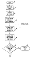
- Figures 5A and 5B form a flow chart which specifically represents the method of the invention as implemented by the computer 12.
- the operator After the probe body (not shown) carrying the probe head 8 has been slidably inserted into a particular heat exchanger tube 3 so that the probe head 8 is adjacent to the region of the tube 3 that the operator wishes to inspect, the operator first selects the precise axial length of the tube 3 that he wishes to scan as indicated by box 52. Next, the computer 12 converts this axial length into numbers of scans, as is indicated by box 54. This is a simple operation, which is determined on the basis of the pitch of the thread of the screw (not shown) used to impart helical motion to the probe body.
- the system operator After the computer 12 has determined the number of scans corresponding to the selected axial length of the tube 3 to be inspected, the system operator next selects an angular increment of data acquisition, as is indicated by box 56. If the operator desires a relatively quick, coarse resolution scan of the tube 3, this angular increment may be as high as 15 degrees. If, on the other hand, he wishes to have a relatively quick, fine resolution scan made of the axial length being inspected, this angular increment may be as low as 1 degree. Normally, to provide for a uniform resolution throughout the entire 360 degrees of the scan, the angular increment chosen will be a number of degrees which is evenly divisible into 360 degrees.
- the computer 12 determines the total number of data increments Nt to be taken by determining the number of angular increments in each scan, and multiplying times the number of scans computed in step 54.
- the drive unit 8.5 that moves the probe head 8 is actuated as is indicated by step 60. This is accomplished by the computer 12 actuating the power switching circuit 9.5, which connects the electric motor of the drive unit 8.5 to a source of electrical power (not shown). Immediately after the motor has been actuated, the output of the optical encoder coupled to the drive unit motor is fed into the input of the computer 12.
- the computer 12 begins to receive an output from the optical encoder of the drive unit 8.5, it inguires whether or not the encoder rotates past a zero degree position within a selected time period, as is indicated by question block 62. If the computer 12 does not receive such a confirmation signal, it displays an error condition, as is indicated by block 63, which informs the operator of the probe system 1 that the motor and encoding unit 8.5 is not properly rotating the probe head 8. If, on the other hand, it receives a signal that indicates that the encoder of the motor and encoder unit 8.5 has swept past a zero degree position within a selected time period, it proceeds to block 64, and actuates the eddy current circuitry 10.
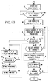
- the computer 12 proceeds to question block 66, and inquires whether or not the drive unit 8.5 has moved the probe head 8 to the beginning of the first data increment. As the data increments are only about 0.152 millimeters apart when the probe head 8 is used to inspect a 15.875 millimeters diameter heat exchanger tube at 1-degree increments, the amount of time necessary for the computer 12 to answer the inquiry in question block 66 in the affirmative is normally only a small fraction of a second. As soon as the computer 12 detects that the beginning of the first data increment has arrived, it immediately begins storing the impedances associated with each coil 32, 34 and 36 as indicated in box 68.
- the computer 12 instructs the frequency multiplexer 11 to conduct current of initial frequencies F1, F2 and F3 through the coils 32, 34 and 36.
- initial frequencies F1, F2 and F3 In the case of an Inconel heat exchanger tube 3 having a wall thickness of approximately F1, F2 and F3 will correspond to 50 kHz, 250 kHz, and 500 kHz, respectively when the outer diameter of the coil 32 is approximately 4.7625 millimeters and the outer diameter of the inner coil 36 is approximately 1.5875 millimeters.
- the computer proceeds to question block 72, and inquires whether or not the eddy current circuitry 10 detects any impedance changes in any of the coils from millisecond to millisecond. If the answer to this inquiry is affirmative (as would be the case when the probe head 8 is swept adjacent to a flaw in the tube wall 2) the computer 12 implements the step indicated in block, 74, and immediately begins changing the frequencies of the currents conducted through the coils 32, 34 and 36 in order to optimize resolution.
- the computer proceeds to question block 76 and inquires whether or not the impedance experienced by any of the coils 32, 34 and 36 has decreased as a result of the changes in frequency of the current conducted therethrough. If the answer to this question is affirmative, then the computer 12 returns to the step indicated in block 74, and continues to change the frequency of the current on a millisecond to millisecond basis.
- the practical effect of the steps indicated in blocks 74 and 76 is for the computer 12 to search out and find the frequency of the currents in the coils 32, 34, and 36 which minimize the coil impedance, and thereby maximize the resolution of the flaw in the tube wall 2.
- the answer to the inquiry in question block 76 will become negative, and the computer 12 will proceed to further optimize resolution by optimizing the phase angle of the alternating currents flowing through the coils 32, 34 and 36, and then optimizing the amplitudes of the resulting signals as is indicated in blocks 78 and 80.
- the computer will proceed to question block 84, and ask whether or not the next data increment N+1 has arrived. If the answer is negative, then the computer 12 will re-execute the step indicated in block 70, and again conduct the initially chosen current frequencies through the various coils, which again will likely result in a near repeat of the steps indicated in block 72 through 80. However, when the answer to this inquiry is affirmative, the computer computes the cylindrical coordinates associated with the data increment step N+1 as is indicated in block 86. It will then immediately display the minimum impedance value associated with each of the coils 32, 34 and 36 within the increment as is indicated in block 88. Lowered impedance values will have the effect of generating hills in the graphic display on the CRT tube 13, such as illustrated in scans 2 through 5 in Figure 1.
- the computer 12 will inquire whether or not the data increment just completed the total number of data increments Nt. If the answer to this question is negative, the computer 12 recommences steps 70 through 90. When, however, the answer to this inquiry is affirmative, the computer 12 stops the operation of the probe system 1, as is indicated by block 92.
- the computer 12 detects no discontinuities in the tube wall 2 in a particular data increment, it answers the question in question block 72 in the negative, and continues to conduct currents through the coils 32, 34 and 36 at the initially chosen frequencies until the end of that data increment. Following this, the computer 12 displays the impedance values at the cylindrical coordinates associated with the no-flaw increment. As the impedance values remain unchanged throughout such a data increment, the resulting display is a straight segment. If no impedance changes are detected throughout a complete scan, the resulting display is a straight line for the entire scan (such as scan No. 1. in Figure 1).
- the general program may be embellished with one or more subroutines which would enhance the resolution of the probe head 8 even more.
- the smallest-diametered coil 36 detects a flaw on the inner surface of the tube wall 2
- the concentrically disposed middle and outer coils 34 and 36 could be operated at the same high frequency for a very small fraction of a second. If one or more of these larger diametered coils simultaneously interacted with this inner surface flaw, the resulting information could help determine the area of the flaw since the area of the coils in the probe head 8 is known.
- Still another subroutine that might be added to the general program is the operation of two of the three coils in a differential mode, in contrast to the operation of all three coils in an absolute mode.
Landscapes
- Chemical & Material Sciences (AREA)
- Chemical Kinetics & Catalysis (AREA)
- Electrochemistry (AREA)
- Physics & Mathematics (AREA)
- Health & Medical Sciences (AREA)
- Life Sciences & Earth Sciences (AREA)
- Analytical Chemistry (AREA)
- Biochemistry (AREA)
- General Health & Medical Sciences (AREA)
- General Physics & Mathematics (AREA)
- Immunology (AREA)
- Pathology (AREA)
- Investigating Or Analyzing Materials By The Use Of Magnetic Means (AREA)
Abstract
Description
-
*Inconel is a registered U.S. trademark belonging to the International Nickel Company, Inc. - This invention generally relates to an eddy current probe system and method, and is specifically concerned with an improved probe system having a plurality of concentrically-disposed coils for simultaneously detecting different types of flaws or discontinuities at different depths within a wall of, for example, an Inconel* tube.
- Eddy current probes for inspecting the walls of metallic conduits are known in the prior art. Such probes are particularly useful in inspecting the Inconel tubes used as heat exchangers in nuclear steam generators for flaws caused by corrosion or fretting. Generally, these eddy current probes comprise a coil mounted in a probe head that is slidably movable within the interior of the tube being inspected, and electrically connected to a current generator which conducts an alternating current through the coil as it is moved. The current generator is typically capable of generating alternating currents having frequencies of between 10 kHz and 1 MHz. An impedance detecting circuit, which may take the form of an inductive bridge, is also connected across the leads of the coil. In operation, the alternating current conducted through the coil excites it into generating a pulsating magnetic field whose magnitude and polarity changes in accordance with the frequency of the current. When the coil of the probe is positioned in the vicinity of an electrically conductive wall, the changing magnetic flux emanating from the coil induces eddy currents in a portion of the wall. The particular voltage, amperage and direction of the eddy currents produced are dependent in part upon the specific impedance of the portion of the wall that conducts the eddy current. Because the direction of flow of the eddy currents generated by the coil is opposite to the current flowing through the probe coil, the magnetic field created by the eddy currents creates an impedance in the probe coil. The impedance experienced by the eddy currents is in turn dependent upon the resistance these currents encounter as they circulate through the wall. Since flaws in the metal wall (such as cracks, pits, or regions of local thinning) create regions of higher resistances at the flaw locations, eddy current probes may be used to locate flaws by constantly monitoring the impedances of the coils as the probe coils are moved along the walls of the tube. Sharp changes in impedance over localized areas would indicate the existence of cracks or pits or other relatively small area flaws, whereas gradual changes in impedance over a broad region of the conduit might indicate large-area flaws such as a grain change in the metal, an area of material creep, or a thinned wall region.
- Typically, such prior art eddy current probes utilize either a single bobbin type coil whose axis of rotation is parallel with the longitudinal axis of the conduit being inspected (and which is operated in an "absolute" mode), or a pair of bobbin coils having the same radius which are spaced apart from one another (which are operated in a "differential" mode). In either case, the probe head containing either the single or the double coil is moved within the interior of the tube along its longitudinal axis. More recently, "pancake-type" probe coil configurations have come in to use. In such configurations, the axis of rotation of the windings of a relatively flat coil is disposed along the radius of the conduit, and the coil is used to scan the inner wall of the conduit by moving it both radially and longitudinally, thereby imparting a helical motion to the coil. Such pancake-type coils are capable of more accurately locating the precise point where some types of flaws reside in the conduit wall. Both configurations have been successfully used in hostile environments where direct inspection of tubing is impossible, such as the walls of the approximately 40 miles of Inconel tubes used as heat exchangers in nuclear steam generators.
- While such probes are capable of performing satisfactory inspections of such heat exchanger tubes, the applicants have noted a number of problems associated with these probes which, up to now, has limited their usefulness. For example, since the depth of penetration of a particular pulsating magnetic field is dependent upon its frequency, it is difficult or impossible for a coil conducting an alternating current of a fixed frequency to simultaneously and reliably resolve flaws at all depths of the conduit wall. Secondly, while a small-diametered coil is best able to accurately pinpoint the location of a particular flaw, such a coil i incapable of transmitting pulsating magnetic fields having frequencies low enough to completely penetrate the conduit walls if the coil diameter is made too small. The applicants have observed that these constraints often necessitate multiple scans of the tube wall with different diametered coils operating at different frequencies if all of the flaws therein are to be accurately and reliably located. However, the multiple scanning of a particular tube wall with different probe coils operating at different current frequencies greatly protracts the time necessary for the testing which in turn results in increased down-time for the steam generator being inspected. As the typical revenue losses associated with such generator down-time often exceeds $100,000.00 a day, the expenses associated with the necessary multiple scans are very substantial. Moreover, such multiple scanning also increases the time that the inspecting personnel are exposed to potentially hazardous radiation, which adds even more to the cost of the eddy current testing.
- In view of the foregoing, the applicants have concluded that there is a need for an eddy current probe system which is capable of accurately and reliably plotting all types of flaws at all different depths within the walls of a small diametered metallic tube with only a single rapid scan. Ideally, such an eddy current probe system would provide better resolution than any prior art probe system or combination of any such systems. Finally, the eddy current probe system should be extremely versatile, and capable of instantaneously adjusting its pulsating magnetic fields for maximum coupling with the flaw areas detected so as to afford maximum resolution under a broad range of conditions.
- Generally speaking, the invention is an improved eddy current probe for simultaneously detecting different types of flaws at different depths. The improved probe includes a current generator for generating alternating currents of substantially different frequencies, and a plurality of concentrically arranged coils, each of which separately communicates with the current generating means and each of which conducts an alternating current of substantially different frequency for detecting different types of flaws at different depths within the metallic wall. A magnetic shielding material is disposed between the edges of adjacent coils for preventing cross-talk between each coil and the pulsating magnetic fields generated by adjacent coils. The probe system further includes an impedance detector circuit for providing an electrical output representative of the relative impedance of the respective coils. Both the current generator means and impedance detector circuit may be parts of a commercially available eddy current testing device.
- Preferably, the highest frequency alternating current is conducted through the coil having the smallest diameter, whereas the lowest frequency alternating current is conducted through the coil having the largest diameter, for two reasons. First, the application of a relatively low frequency alternating current to the largest diameter coil insures that at least one of the pulsating fields emanating from the coils will penetrate far enough into the tube wall and resolve flaws located on the exterior tube surface, such as areas of grain change, creep and wall thinning due to corrosion, fretting or mechanical scratching. Second, the application of a relatively high frequency alternating current to the smallest diameter coil not only allows this coil to detect and to pinpoint the location of small area flaws such as cracks and pits, but also creates a small and well defined reference point that the probe system operator may use to infer the location of all of the other coils in the probe head at all times. The probe head of the preferred embodiment includes three concentrically disposed coils of progressively larger diameter which may conduct frequencies as high as 1.0 MHz and as low as 30 kHz. The inner coil preferably initially conducts an alternating current of approximately 500 kHz, the middle coil a current of approximately 250 kHz, and the outer coil a current of approximately 50 kHz.
- Finally, the improved eddy current probe system may include a computer connected to both the impedance detector circuit and the current generator for adjusting and multiplexing the frequencies of the alternating current conductedhrough the coils of the probe head as the head is moved along a selected portion of the metallic wall and comparing the resulting amounts of coil impedance detected in order to minimize the impedance of each coil and hence to maximize the flaw-detecting resolution of the probe head.
- In the method of the invention, the computer receives and stores the value of the impedance of each coil as the probe is helically moved around the interior of the tube wall. When impedance changes are detected, the computer incrementally adjusts the frequencies of these currents either upwardly or downwardly, and compares the values of the impedances of each coil associated with both the old frequency and the new incrementally adjusted frequency. The computer makes subsequent incremental adjustments to the alternating current frequencies based on the resulting comparisons for the purpose of arriving at the minimum impedance values achievable with the coils. When such maximum impedances are obtained, the resolution of the probe head, as a whole, is maximized.
- The probe system of the invention obviates the need for multiple scans of the tube wall being inspected. The concentric arrangement of the coils locates flaws and other discontinuities in a faster and more accurate manner than would a colinear or other multiple arrangement of such coils due to the clear reference point provided by the centrally disposed, small diameter coil which preferably transmits a sharply focused, high-frequency pulsating magnetic field. Finally, the near-instantaneous, impedance minimizing adjustments of the frequencies of the alternating currents conducted through the various diametered coils insured that the resolution of the probe head will be maximized at every point of inspection without any significant sacrifice in scanning time.
-
- Figure 1 is a schematic representation of the overall system of the invention, illustrating both the manner in which the probe head scans a tube, the manner in which the probe output is displayed, and the lay-out of the components of the eddy current circuitry that implements the method of the invention;
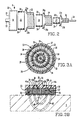
- Figure 2 is an exploded, side view of the probe head of the invention;
- Figure 3A is a plan view of the probe head illustrated in Figure 2 with the coils shown in phantom;
- Figure 3B is a cross-sectional side view of the probe head illustrated in Figure 3A;
- Figures 4A and 4B are a schematic diagram of a pancake-type eddy current probe coil, and a graph representing the relationship between the depth of penetration of the pulsating magnetic field emanated by a particular probe coil as a function both of the diameter of the probe, and the frequency of the alternating current applied thereto, and
- Figures 5A and 5B together form a flow chart illustrating the preferred method of the invention as implemented by the circuitry illustrated in Figure 1.
- With reference now to Figure 1, wherein like numbers designate like components throughout all the several figures, the eddy
current probe system 1 of the invention is particularly well adapted for inspecting thewalls 2 of anInconel tube 3 of the type used in nuclear steam generators for different types of flaws at different depths within thewalls 2, such as cracks 4 (both axially and radially aligned), pits 5, andbroader sections 6 of the tube wall which have been subjected to creep or grain change, or thinned by corrosion, fretting or mechanical abrasion. Theprobe system 1 includes aprobe head 8 which emanates a magnetic field 9 generated by a multiplicity of concentrically-arranged coils, each of which conducts a different frequency alternating current. Theprobe head 8 is mechanically mounted in a probe body (not shown) that is moved along a helical path by a drive unit 8.5 that includes an electric drive motor coupled to an optical encoder. The drive unit 8.5 is selectively actuated by a switching circuit 9.5 that is in turn connected to a power source (not shown). - The
probe head 8 is electrically connected via a cable to eddy current circuitry generally designated at 10. This eddycurrent circuitry 10 includes a computer-compatible frequency multiplexer 11 which, in the preferred embodiment, is a model MIZ 18 manufactured by ZETEC, Inc., located in Isaquah, Washington, USA. The frequency multiplexer 11 is connected to acomputer 12 which is programmed to adjust the frequencies of the currents conducted through the coils of theprobe head 8 to optimize resolution whenever an impedance change indicative of a flaw or other discontinuity is detected. In the preferred embodiment, thecomputer 12 is preferably a Model HP 9836 and an IEEE 488 interface circuit manufactured by Hewlett-Packard located in Palo Alto, California, USA, modified by a Zetec DDA-4 processing package. - The output of the
computer 12 is connected to a cathode ray tube (CRT) 13 which displays, through selected computer graphics, the impedance changes experienced by the coils within theprobe head 8 as they are helically moved around the inner surface of thewall 2 of theInconel tube 3. The frequency multiplexer 11 includes a current generator 14 for generating a multiplicity of alternating currents. The leads of the concentrically arranged coils within theprobe head 8 are connected to the current generator 14 by way of a switching circuit 15. This switching circuit 15 acts to selectively conduct the same current through one or more of the concentrically arranged coils in theprobe head 8 when the overall resolution of thesystem 1 would be enhanced by such an interconnection. The current generator 14 is connected to and controlled by a frequency adjusting andtiming circuit 16. Thecircuit 16 is capable of not only changing the frequency of the currents conducted through each of the concentrically arranged coils of theprobe head 8, but also of multiplexing a sequence of different-frequency currents through each of the coils. Finally, the frequency multiplexer 11 includes animpedance measuring circuit 17 which may be an inductive bridge connected to the current generator 14 for measuring changes in impedance experienced by the concentrically arranged coils in theprobe head 8 as they are helically moved along thetube 3.
*Delrin is a registered U.S. trademark belonging to E.I. DuPont De Nemours and Company of Wilmington, Delaware, USA. - In operation, the
probe head 8 is mounted within a probe body, such as the Delrin* probe carrier of the combined ultrasonic and eddy current inspection probe described and claimed in co-pending U.S. Patent Application Serial No. 079,860, filed July 30, 1987, by Thomas Arzenti and assigned to the Westinghouse Electric Corporation, the entire specification of which is incorporated herein by reference. The probe carrier of the aforementioned probe helically moves theprobe head 8 in wiping engagement with the inner surface of thewall 2 of anInconel tube 3 to scan the same. As is indicated in Figure 1, such helical motion includes an axial component along the longitudinal axis Y of thetube 3, as well as an angular component w along the radium r of thetube 3. As will be described in more detail hereinafter, as theprobe head 8 is scanningly moved throughout the inner surface of thetube wall 2, different frequencies of alternating current are conducted through different probe coils so as to generate a plurality of different shaped pulsating magnetic fields. At least one of these coils generates a field that penetrates completely through thewall 2 of thetube 3 so that exterior surface flaws such as the thinnedportion 6 of the tube may be detected. At least one of the coils generates a magnetic field which interacts substantially with the inner surface of thewall 2 of thetube 3 so that interior surface flaws such as pit 5 which exist predominantly in the interior portion of thewall 2. Finally, at least one of the coils in theprobe head 8 generates a pulsating - magnetic field whose lines of flux interact principally with the interior portion of the
wall 2 in order to resolve flaws such as thecracks 4 which extends completely through thewall 2 of thetube 3. - The results of the scan may be displayed on the
CRT tube 13 by way of computer graphics wherein the vertical axis designates the impedance changes experienced by each of the coils, the perspective axis represents the longitudinal axis Y of thetube 3 and the horizontal axis represents the angular location of theprobe head 8 with respect to the radius of thetube 3. Preferably, each one of the ten scans illustrated on theCRT screen 13 includes a different-colored output for each of the coils in theprobe head 8. In the preferred embodiment of the invention, three coils are used in theprobe head 8, although many more of such coils may be used if desired. In the graph displayed onCRT screen 13, the output of the small-frequency coil is illustrated by a small-dashed line, while the output of the medium and low frequency coils are represented by large-dashed and solid lines, respectively. In the preferred embodiment, the small, medium and large diametered coils are initially operated at 500, 250 and 50 kHz respectively, and are adjusted to maximize the resolution of theprobe system 1 when an impedance change indicative of a flaw is detected. -
*Co-netic and Netic are registered U.S. trademarks owned by the Magnetic Shield Division of Perfection Mica Co. of Bensenville, Illinois, USA. - With reference now to Figures 2, 3A and 3B, the exterior of the
probe head 8 is formed by acasing 19 preferably fabricated from a plastic material such as Delrin. Thecasing 19 includes a ring-shapedside wall 20 for retaining the coils and theprobe head 8, as well as acircular back plate 21 having a centrally disposed mountinglug 22 projecting therefrom. In the preferred embodiment, the ring-shapedside wall 20, thecircular back plate 21 and mountinglug 22 are all integrally formed. The interior of theprobe head 8 includes outer, middle andinner shield walls shield walls ring 29 of material that is very high in magnetic permeability which is closely circumscribed by aring 30 of material which is somewhat lower in magnetic permeability but which has higher saturation characteristics than thering 29 that it circumscribes. In the preferred embodiment, theinner ring 29 of each shield is formed from Netic* foil. The ring-shapedshield walls coils probe system 1. As is evident in Figure 2, each of thecoils leads ferrite focusing core 39 is centrally disposed within theinner coil 36 in order to both focus and intensify the pulsating magnetic field generated thereby, thereby advantageously creating a reference point for inferring the location of the surroundingcoils - In the preferred embodiment, both the outer, middle and inner probe coils 32, 34 and 36 are formed from about thirty windings of copper wire. As the outer diame ter of the
probe head 8 is only about 4.7625 millimeters, these windings are formed from very thin wire. In the alternative, the coil windings may also be formed from state-of-the-art printed circuit board techniques. Probe head coils formed by way of this latter method are advantageously flatter than coils formed by bobbin-like windings of copper wire. Such extreme flatness might have the affect of increasing the overall resolution of theprobe head 8 since the fields generated by thecoils probe head 8, where they might have an opportunity to interact with a metallic body which is not the particular portion of theconduit wall 2 being inspected. In both embodiments, the front face of theprobe head 8 is coated with a thin layer of Delrin or some other self-lubricating plastic material both to protect the delicate coil windings, and to minimize friction as theprobe head 8 helically rides along the inner surface of thetube wall 2 being inspected. - With reference now to Figures 3A and 3B, the
casing 19 of theprobe head 8 further includes three pairs of lead bores 41a, 41b, 42a, 42b, and 43a, 43b for conducting thelead wires coils - The general operation of the
probe head 8 may best be understood with reference to Figures 3B, 4A and 4B. At the beginning of each data increment, the frequencies of the currents conducted through thecoils diametered coil 32 will penetrate completely through thewall 2 of theInconel tube 3 being inspected, while the field 47 emanated by the smallest-diametered coil 36 will only shallowly penetrate into the inner surface of thewall 2. The field 46 emanated by the middle-diametered coil 34 interacts primarily with the interior of thewall 2 of thetube 3. Such a field shape insures that no signifi cant discontinuity at any point long the wall thickness will be overlooked by theprobe system 1. - While it would be possible to operate the largest-
diametered coil 32 at the highest frequency, and thesmallest diametered coil 36 at the lowest frequency, such a mode of operation is normally not preferred by virtue of the limitations illustrated in the graph of Figure 4B. This graph demonstrates that the depth of penetration of the pulsating magnetic field emanating from a particular coil is dependent not only upon the frequency of the current conducted through the coil, but also upon the diameter of the coil. This graph also illustrates that, in order to achieve a particular depth of penetration P, the coil diameter D must be of a certain minimal size before any effective penetration can take place, no matter how low the frequency of the current conducted thereby. Hence, the diameter of the smallest-diametered coil 36 may well be below the minimum size diameter necessary to project a pulsating magnetic field completely through thewall 2 of anInconel tube 3. Of course, the diameter of thesmallest diametered coil 36 could be made large enough to project a field through thewall 2. But if this were done, the resolution ability of theprobe head 8 might be seriously diminished, since the resulting large coils would not be capable of accurately locating the borders of small area flaws. For all these reasons, the smallest-diametered coil 36 is generally operated at the highest frequency, while the largest-diametered coil 32 is operated at the lowest frequencies. - Figures 5A and 5B form a flow chart which specifically represents the method of the invention as implemented by the
computer 12. After the probe body (not shown) carrying theprobe head 8 has been slidably inserted into a particularheat exchanger tube 3 so that theprobe head 8 is adjacent to the region of thetube 3 that the operator wishes to inspect, the operator first selects the precise axial length of thetube 3 that he wishes to scan as indicated bybox 52. Next, thecomputer 12 converts this axial length into numbers of scans, as is indicated bybox 54. This is a simple operation, which is determined on the basis of the pitch of the thread of the screw (not shown) used to impart helical motion to the probe body. - After the
computer 12 has determined the number of scans corresponding to the selected axial length of thetube 3 to be inspected, the system operator next selects an angular increment of data acquisition, as is indicated bybox 56. If the operator desires a relatively quick, coarse resolution scan of thetube 3, this angular increment may be as high as 15 degrees. If, on the other hand, he wishes to have a relatively quick, fine resolution scan made of the axial length being inspected, this angular increment may be as low as 1 degree. Normally, to provide for a uniform resolution throughout the entire 360 degrees of the scan, the angular increment chosen will be a number of degrees which is evenly divisible into 360 degrees. - In the next step of the method, the
computer 12 determines the total number of data increments Nt to be taken by determining the number of angular increments in each scan, and multiplying times the number of scans computed instep 54. After this has been accomplished, the drive unit 8.5 that moves theprobe head 8 is actuated as is indicated bystep 60. This is accomplished by thecomputer 12 actuating the power switching circuit 9.5, which connects the electric motor of the drive unit 8.5 to a source of electrical power (not shown). Immediately after the motor has been actuated, the output of the optical encoder coupled to the drive unit motor is fed into the input of thecomputer 12. - Once the
computer 12 begins to receive an output from the optical encoder of the drive unit 8.5, it inguires whether or not the encoder rotates past a zero degree position within a selected time period, as is indicated byquestion block 62. If thecomputer 12 does not receive such a confirmation signal, it displays an error condition, as is indicated byblock 63, which informs the operator of theprobe system 1 that the motor and encoding unit 8.5 is not properly rotating theprobe head 8. If, on the other hand, it receives a signal that indicates that the encoder of the motor and encoder unit 8.5 has swept past a zero degree position within a selected time period, it proceeds to block 64, and actuates theeddy current circuitry 10. - After the
eddy current circuitry 10 has been actuated, thecomputer 12 proceeds to questionblock 66, and inquires whether or not the drive unit 8.5 has moved theprobe head 8 to the beginning of the first data increment. As the data increments are only about 0.152 millimeters apart when theprobe head 8 is used to inspect a 15.875 millimeters diameter heat exchanger tube at 1-degree increments, the amount of time necessary for thecomputer 12 to answer the inquiry inquestion block 66 in the affirmative is normally only a small fraction of a second. As soon as thecomputer 12 detects that the beginning of the first data increment has arrived, it immediately begins storing the impedances associated with eachcoil box 68. At substantially the same time, thecomputer 12 instructs the frequency multiplexer 11 to conduct current of initial frequencies F1, F2 and F3 through thecoils heat exchanger tube 3 having a wall thickness of approximately F1, F2 and F3 will correspond to 50 kHz, 250 kHz, and 500 kHz, respectively when the outer diameter of thecoil 32 is approximately 4.7625 millimeters and the outer diameter of theinner coil 36 is approximately 1.5875 millimeters. The applicants have observed that the conduction of currents of such frequencies into coils of such diameters result in magnetic fields that interact with tube walls of such thicknesses in much the fashion shown in Figure 3B, wherein the field lines 45 emanated by the largest-diametered coil 32 penetrate completely through thewall 2 of thetube 3, and the field lines 46 and 47 of the mid-diametered and smallest-diametered coils wall 2 as illustrated. - Immediately at the commencement of the first data increment, the computer proceeds to question
block 72, and inquires whether or not theeddy current circuitry 10 detects any impedance changes in any of the coils from millisecond to millisecond. If the answer to this inquiry is affirmative (as would be the case when theprobe head 8 is swept adjacent to a flaw in the tube wall 2) thecomputer 12 implements the step indicated in block, 74, and immediately begins changing the frequencies of the currents conducted through thecoils block 76 and inquires whether or not the impedance experienced by any of thecoils computer 12 returns to the step indicated inblock 74, and continues to change the frequency of the current on a millisecond to millisecond basis. Of course, the practical effect of the steps indicated inblocks computer 12 to search out and find the frequency of the currents in thecoils tube wall 2. - Once these optimum frequencies have been found, the answer to the inquiry in
question block 76 will become negative, and thecomputer 12 will proceed to further optimize resolution by optimizing the phase angle of the alternating currents flowing through thecoils blocks - Immediately after all of the optimization steps 74 through 80 have been completed, the computer will proceed to question
block 84, and ask whether or not the next data increment N+1 has arrived. If the answer is negative, then thecomputer 12 will re-execute the step indicated inblock 70, and again conduct the initially chosen current frequencies through the various coils, which again will likely result in a near repeat of the steps indicated inblock 72 through 80. However, when the answer to this inquiry is affirmative, the computer computes the cylindrical coordinates associated with the data increment step N+1 as is indicated inblock 86. It will then immediately display the minimum impedance value associated with each of thecoils block 88. Lowered impedance values will have the effect of generating hills in the graphic display on theCRT tube 13, such as illustrated inscans 2 through 5 in Figure 1. - Next, as is indicated by
question block 90, thecomputer 12 will inquire whether or not the data increment just completed the total number of data increments Nt. If the answer to this question is negative, thecomputer 12 recommencessteps 70 through 90. When, however, the answer to this inquiry is affirmative, thecomputer 12 stops the operation of theprobe system 1, as is indicated byblock 92. - Of course, if the
computer 12 detects no discontinuities in thetube wall 2 in a particular data increment, it answers the question inquestion block 72 in the negative, and continues to conduct currents through thecoils computer 12 displays the impedance values at the cylindrical coordinates associated with the no-flaw increment. As the impedance values remain unchanged throughout such a data increment, the resulting display is a straight segment. If no impedance changes are detected throughout a complete scan, the resulting display is a straight line for the entire scan (such as scan No. 1. in Figure 1). - While the flowchart of the method of the invention has been described only in terms of changing the frequencies of the currents conducted through the
coils probe head 8 even more. For example, when the smallest-diametered coil 36 detects a flaw on the inner surface of thetube wall 2, the concentrically disposed middle andouter coils probe head 8 is known. Still another subroutine that might be added to the general program is the operation of two of the three coils in a differential mode, in contrast to the operation of all three coils in an absolute mode. - While the aforementioned method of the invention has been described with respect to the use of three coils, it is also adaptable for use with a
probe head 8 having more than three coils. If more than three coils are used, a larger span if initially chosen frequencies are preferably used, which would have the effect of increasing the overall resolution of thesystem 1 even more.

Claims (15)
Applications Claiming Priority (2)
| Application Number | Priority Date | Filing Date | Title |
|---|---|---|---|
| US167289 | 1980-07-09 | ||
| US07/167,289 US4855677A (en) | 1988-03-11 | 1988-03-11 | Multiple coil eddy current probe and method of flaw detection |
Publications (2)
| Publication Number | Publication Date |
|---|---|
| EP0332048A2 true EP0332048A2 (en) | 1989-09-13 |
| EP0332048A3 EP0332048A3 (en) | 1990-08-08 |
Family
ID=22606743
Family Applications (1)
| Application Number | Title | Priority Date | Filing Date |
|---|---|---|---|
| EP89103630A Withdrawn EP0332048A3 (en) | 1988-03-11 | 1989-03-02 | Multiple coil eddy current probe and method of flaw detection |
Country Status (3)
| Country | Link |
|---|---|
| US (1) | US4855677A (en) |
| EP (1) | EP0332048A3 (en) |
| JP (1) | JPH01274058A (en) |
Cited By (17)
| Publication number | Priority date | Publication date | Assignee | Title |
|---|---|---|---|---|
| GB2245072A (en) * | 1990-06-08 | 1991-12-18 | Ca Atomic Energy Ltd | Eddy current probe for detecting internal defects in ferromagnetic tubes |
| FR2663746A1 (en) * | 1990-06-08 | 1991-12-27 | Ca Atomic Energy Ltd | FOURCAULT CURRENT PROBE FOR DETECTING DEFECTS LOCATED IN A TUBE OF FERROMAGNETIC MATERIAL. |
| GB2224575B (en) * | 1988-11-04 | 1993-07-14 | Technical Software Consultants | Electromagnetic microscope |
| FR2690744A1 (en) * | 1992-04-30 | 1993-11-05 | Electricite De France | Detecting defects in non-magnetic metals using eddy currents - by using the independent receptors at different angles around emitting coil to detect cracks in different directions |
| FR2703465A1 (en) * | 1993-04-02 | 1994-10-07 | Bosch Gmbh Robert | Method and control probe for non-destructive testing of the surface of electrically conductive materials |
| WO1996034279A1 (en) * | 1995-04-24 | 1996-10-31 | Larsson Goeran | Method and device for measuring ferro-magnetic objects |
| GB2313913A (en) * | 1996-06-07 | 1997-12-10 | Somerset Technical Lab Ltd | Non-destructive testing for surface flaws on massive electrically-conductive components |
| EP0816838A1 (en) * | 1996-06-25 | 1998-01-07 | Halliburton Company | Apparatus and method for well bore casing inspection |
| DE19819066A1 (en) * | 1998-04-29 | 1999-11-11 | F I T Messtechnik Gmbh | Test method for non-contact detection of irregularities in the wall thickness of inaccessible metallic pipes |
| GB2361065A (en) * | 2000-04-05 | 2001-10-10 | Andrew Michael Pratt | Flaw detecting probe and method |
| EP0959349A3 (en) * | 1998-05-18 | 2002-04-17 | MANNESMANN Aktiengesellschaft | Magnetic leakage probe for nondestructive testing of long, rotation-symetric bodies |
| FR2825800A1 (en) * | 2001-06-12 | 2002-12-13 | Boeing Co | Eddy current method for detecting sub-surface defects in metallic substrates, e.g. for detecting corrosion defects in aircraft, based on inspection of components using Eddy current probes of different frequencies |
| EP1783501A3 (en) * | 2005-11-03 | 2008-02-27 | The Boeing Company | Systems and methods for inspecting electrical conductivity in composite materials |
| WO2011086414A1 (en) * | 2010-01-14 | 2011-07-21 | Toyota Jidosha Kabushiki Kaisha | Eddy current measuring sensor and inspection method using this eddy current measuring sensor |
| WO2012021034A3 (en) * | 2010-08-12 | 2012-05-10 | 한국원자력연구원 | Conductor thickness detecting device using a double core |
| WO2017091204A1 (en) * | 2015-11-24 | 2017-06-01 | Halliburton Energy Services, Inc. | Selective pipe inspection |
| CN114485367A (en) * | 2022-01-20 | 2022-05-13 | 株洲中航科技发展有限公司 | Probe of inductive displacement sensor, probe coil excitation method and inductive displacement sensor |
Families Citing this family (75)
| Publication number | Priority date | Publication date | Assignee | Title |
|---|---|---|---|---|
| US5030911A (en) * | 1980-10-19 | 1991-07-09 | Baker Hughes Incorporated | Method and apparatus for displaying defects in tubular members on a two-dimensional map in a variety of display modes |
| US4949044A (en) * | 1988-04-18 | 1990-08-14 | Resonance Research, Inc. | Apparatus for mapping a static magnetic field |
| US5008621A (en) * | 1989-04-14 | 1991-04-16 | Iowa State University Research Foundation, Inc. | Multiparameter magnetic inspection system with magnetic field control and plural magnetic transducers |
| GB2235559A (en) * | 1989-08-21 | 1991-03-06 | Mars Inc | Coin testing apparatus |
| US5068608A (en) * | 1989-10-30 | 1991-11-26 | Westinghouse Electric Corp. | Multiple coil eddy current probe system and method for determining the length of a discontinuity |
| US5021738A (en) * | 1990-03-26 | 1991-06-04 | The United States Of America As Represented By The Secretary Of The Navy | Field variable, electronically controlled, nested coil eddy current probe |
| US5200704A (en) * | 1991-02-28 | 1993-04-06 | Westinghouse Electric Corp. | System and method including a buried flexible sheet target impregnated with ferromagnetic particles and eddy current probe for determining proximity of a non-conductive underground structure |
| US5237271A (en) * | 1991-05-06 | 1993-08-17 | General Electric Company | Apparatus and method for non-destructive testing using multi-frequency eddy currents |
| US5313405A (en) * | 1991-09-04 | 1994-05-17 | Iowa State University Research Foundation, Inc. | System and method for non-destructive evaluation of surface characteristics of a magnetic material |
| US5142230A (en) * | 1991-11-05 | 1992-08-25 | Electric Power Research Institute, Inc. | Scanning device and method for automated eddy current inspection of electrical generator retaining rings |
| US5270647A (en) * | 1992-01-08 | 1993-12-14 | Osaka Gas Company, Ltd. | Pipe electromagnetic field simulation apparatus using Born's approximation rule |
| WO1993015396A1 (en) * | 1992-01-31 | 1993-08-05 | Northrop Corporation | Arrayed eddy current probe system |
| US5293119A (en) * | 1992-02-20 | 1994-03-08 | Sqm Technology, Inc. | Electromagnetic microscope for evaluation of electrically conductive and magnetic materials |
| US5408883A (en) * | 1992-06-09 | 1995-04-25 | Westinghouse Electric Corporation | Remotely operated diagnostic tube sampling device and method of sampling |
| US5394083A (en) * | 1992-08-20 | 1995-02-28 | Iowa State University Research Foundation, Inc. | Magnetic imaging system for display of local variations of magnetic properties in magnetic material |
| US5333502A (en) * | 1992-09-16 | 1994-08-02 | Westinghouse Electric Corp. | Method and apparatus for monitoring the environment of a vessel |
| US5397985A (en) * | 1993-02-09 | 1995-03-14 | Mobil Oil Corporation | Method for the imaging of casing morphology by twice integrating magnetic flux density signals |
| US5396800A (en) * | 1993-03-17 | 1995-03-14 | Westinghouse Electric Corporation | Apparatus and method for inspecting a control rod drive mechanism penetration tube for degradation |
| US5623204A (en) * | 1993-05-17 | 1997-04-22 | Wilkerson; Brian | Eddy current probe |
| US5430376A (en) * | 1993-06-09 | 1995-07-04 | General Electric Company | Combined thermoelectric and eddy-current method and apparatus for nondestructive testing of metallic of semiconductor coated objects |
| US5698977A (en) * | 1993-10-12 | 1997-12-16 | The United States Of America As Represented By The Administrator Of The National Aeronautics And Space Administration | Eddy current method for fatigue testing |
| US5418823A (en) * | 1994-01-04 | 1995-05-23 | General Electric Company | Combined ultrasonic and eddy-current method and apparatus for non-destructive testing of tubular objects to determine thickness of metallic linings or coatings |
| US5544953A (en) * | 1994-05-18 | 1996-08-13 | General Electric Co. | Rolling-ball thermoelectric potential probe and housing for nondestructive testing of metallic and semiconductor objects |
| US5623427A (en) * | 1994-09-02 | 1997-04-22 | Defelsko Corporation | Nondestructive anodic capacity gauge |
| US5926020A (en) * | 1994-11-16 | 1999-07-20 | Samson; Rock | Eddy current hybrid probe with movable magnetic field altering member |
| US5903477A (en) * | 1996-04-10 | 1999-05-11 | Fujitsu Limited | Simulation apparatus and simulation method for electromagnetic field intensity using moment method |
| EP0819944A1 (en) * | 1996-07-16 | 1998-01-21 | Lucent Technologies Inc. | Eddy current sensor |
| US6285183B1 (en) * | 1996-09-30 | 2001-09-04 | Mcdonnell Douglas Corporation | Method and system for measuring the volume loss of a metal substrate |
| US5895439A (en) * | 1996-10-15 | 1999-04-20 | Southwest Research Institute | Method for generating and displaying complex data derived from non-destructive evaluation scanning |
| AUPP813499A0 (en) * | 1999-01-13 | 1999-02-04 | Rock Solid Research Pty. Ltd. | A subsurface pipeline inspection probe |
| US7209844B2 (en) * | 2003-09-19 | 2007-04-24 | Automotive Systems Laboratory, Inc. | Magnetic crash sensor |
| US7514917B2 (en) * | 2003-09-19 | 2009-04-07 | Automotive Systems Laboratory, Inc. | Magnetic crash sensor |
| US20070188168A1 (en) * | 1999-08-26 | 2007-08-16 | Stanley James G | Magnetic sensor |
| US20080109177A1 (en) * | 2003-09-19 | 2008-05-08 | Cech Leonard S | Magnetic crash sensor |
| US8180585B2 (en) * | 1999-08-26 | 2012-05-15 | Tk Holdings, Inc. | Magnetic crash sensor |
| US6703831B1 (en) | 1999-11-12 | 2004-03-09 | Quantech, Inc. | Dual eddy current probe for detecting geometrical differences especially as related to threaded apertures and studs |
| US6281678B1 (en) | 2000-02-29 | 2001-08-28 | Gene R Auville | Tri-tip probe |
| US7023205B1 (en) | 2000-08-01 | 2006-04-04 | General Dynamics Advanced Information Systems, Inc. | Eddy current sensor capable of sensing through a conductive barrier |
| CA2361813A1 (en) * | 2001-01-29 | 2002-07-29 | Peter O. Paulson | Low frequency electromagnetic analysis of prestressed concrete tensioning strands |
| US6525539B2 (en) * | 2001-03-15 | 2003-02-25 | Witten Technologies Inc. | Apparatus and method for locating subsurface objects in conductive soils by measurements of magnetic fields by induced currents with an array of multiple receivers |
| US7463987B2 (en) * | 2003-09-19 | 2008-12-09 | Takata Holdings, Inc. | Magnetic sensing system and method |
| US7839143B2 (en) * | 2003-09-19 | 2010-11-23 | Tk Holdings Inc. | Eddy current magnetic crash sensor |
| US7772839B2 (en) * | 2003-09-19 | 2010-08-10 | Tk Holdings, Inc. | Eddy current magnetic crash sensor |
| JP2007510134A (en) * | 2003-09-19 | 2007-04-19 | オートモーティブ システムズ ラボラトリー インコーポレーテッド | Magnetic collision detection method |
| US7839142B2 (en) * | 2003-09-19 | 2010-11-23 | Tk Holdings, Inc. | Magnetic crash sensor |
| US7218101B2 (en) * | 2003-12-19 | 2007-05-15 | Westinghouse Electric Co. Llc | Eddy current method of inspecting a pressure vessel shell |
| CN101035699A (en) * | 2003-12-21 | 2007-09-12 | 汽车系统实验室公司 | Magnetic sensor |
| CA2504908A1 (en) * | 2004-04-23 | 2005-10-23 | Innovative Materials Testing Technologies, Inc. | Apparatus and method for eddy-current magnetic scanning a surface to detect sub-surface cracks around a boundary |
| GB0428138D0 (en) * | 2004-12-23 | 2005-01-26 | Aea Technology Plc | Detecting failures in flexible multistrand steel structures |
| US20060164091A1 (en) * | 2005-01-26 | 2006-07-27 | Battelle Memorial Institute | Rotating magnet-induced current pipeline inspection tool and method |
| US7626383B1 (en) | 2005-04-25 | 2009-12-01 | Innovative Materials Testing Technologies, Inc. | Apparatus and method for holding a rotatable eddy-current magnetic probe, and for rotating the probe around a boundary |
| JP2009507210A (en) * | 2005-07-29 | 2009-02-19 | オートモーティブ システムズ ラボラトリー インコーポレーテッド | Magnetic collision sensor |
| JP4762672B2 (en) * | 2005-10-27 | 2011-08-31 | 非破壊検査株式会社 | Magnetic material bending portion fracture inspection method and inspection apparatus |
| US7560920B1 (en) | 2005-10-28 | 2009-07-14 | Innovative Materials Testing Technologies, Inc. | Apparatus and method for eddy-current scanning of a surface to detect cracks and other defects |
| JP2008032575A (en) * | 2006-07-29 | 2008-02-14 | Nippon Hihakai Kensa Kk | Eddy current measuring probe and flaw detector using the same |
| US9177371B2 (en) * | 2008-06-09 | 2015-11-03 | Siemens Energy, Inc. | Non-destructive examination data visualization and analysis |
| DE102009010943A1 (en) * | 2009-02-27 | 2010-09-16 | Hilti Aktiengesellschaft | Operating method and coil arrangement for a magnetic sensor for detecting metallic objects in a subsurface |
| US8527216B2 (en) * | 2009-07-24 | 2013-09-03 | Areva Np Inc | Eddy current for the characterization of broached tube support plate blockage |
| JP5981706B2 (en) * | 2011-11-16 | 2016-08-31 | 偕成エンジニア株式会社 | Electromagnetic induction type inspection method and electromagnetic induction type inspection device |
| JP5829930B2 (en) * | 2012-01-27 | 2015-12-09 | 日立Geニュークリア・エナジー株式会社 | Eddy current flaw detection system and eddy current flaw detection method |
| CN102879461B (en) * | 2012-09-30 | 2014-12-03 | 爱德森(厦门)电子有限公司 | Non-directional electromagnetic detecting sensor based on crosslinking differential detecting principle |
| CN105308686B (en) | 2013-05-31 | 2019-06-11 | 纽斯高动力有限责任公司 | Check the steam generator |
| US10060881B2 (en) | 2014-04-16 | 2018-08-28 | Texas Instruments Incorporated | Surface sensing method for corrosion sensing via magnetic modulation |
| JP6452558B2 (en) * | 2015-06-16 | 2019-01-16 | 東亜非破壊検査株式会社 | Method and apparatus for measuring thinning of outer surface of buried pipe, etc. |
| EP3329270B1 (en) * | 2015-07-28 | 2023-11-29 | Zetec, Inc. | Eddy current generation system |
| KR101757589B1 (en) * | 2016-04-20 | 2017-07-12 | 한국수력원자력 주식회사 | An Eddy Current Probe with Multi-Array Coil and Switching Devic |
| US11549831B2 (en) * | 2016-05-13 | 2023-01-10 | Jentek Sensors, Inc. | Measurement system and method of use |
| CN108845025B (en) * | 2018-05-30 | 2022-09-13 | 中国航发动力股份有限公司 | Eddy current detection system and method for pin hole with copper bush |
| CN110006989A (en) * | 2019-04-03 | 2019-07-12 | 陈岩 | A kind of magnetic fault detection system |
| CN111719280B (en) * | 2020-06-29 | 2023-05-16 | 河北烨和祥新材料科技有限公司 | An embossing method for an energy-saving and high-efficiency embossing machine |
| CN112034037B (en) * | 2020-09-25 | 2023-07-25 | 北方民族大学 | An eddy current synchronous detection method and probe for multiple types of defects |
| CN112730603B (en) * | 2020-10-13 | 2024-07-12 | 爱德森(厦门)电子有限公司 | Method for improving crack depth detection range of eddy current detection and system device thereof |
| US12298274B2 (en) * | 2022-09-05 | 2025-05-13 | General Electric Company | Flexible sensor assembly |
| CN119310175A (en) * | 2024-10-14 | 2025-01-14 | 西安交通大学 | Eddy current detection probe and method capable of identifying any crack and direction around a hole |
| CN120214079B (en) * | 2025-04-07 | 2025-09-16 | 皓瑞检测科技(苏州)有限公司 | Power battery detection method, system, probe mechanism and equipment |
Family Cites Families (17)
| Publication number | Priority date | Publication date | Assignee | Title |
|---|---|---|---|---|
| US2992390A (en) * | 1956-06-18 | 1961-07-11 | Continental Oil Co | Method and apparatus for electrical testing of pipe |
| GB1484357A (en) * | 1974-02-23 | 1977-09-01 | Nihon Densokki Kk | Magnetic metal inspection apparatus |
| DE2600206C2 (en) * | 1975-01-06 | 1986-01-09 | The Reluxtrol Co., Seattle, Wash. | Device for non-destructive material testing using the eddy current method |
| DE2509927C3 (en) * | 1975-03-07 | 1980-08-14 | Institut Dr. Friedrich Foerster Pruefgeraetebau, 7410 Reutlingen | Eddy current test coil arrangement |
| SU673904A1 (en) * | 1977-04-11 | 1979-07-15 | Ростовский-На-Дону Институт Сельскохозяйственного Машиностроения | Pulsed induction method of measuring physico-mechanical parameters of ferromagnetic materials and apparatus for effecting same |
| DE2725354C2 (en) * | 1977-06-04 | 1986-06-12 | SKF GmbH, 8720 Schweinfurt | Test head for inductive surface testing of metallic workpieces |
| US4355281A (en) * | 1978-06-14 | 1982-10-19 | Republic Steel Corporation | Eddy current surface flaw detection employing signal correlation |
| US4325026A (en) * | 1979-03-19 | 1982-04-13 | Westinghouse Electric Corp. | Plural coil eddy current mapping probe |
| DE2937650C2 (en) * | 1979-09-18 | 1981-07-30 | Institut Dr. Friedrich Förster Prüfgerätebau, 7410 Reutlingen | Eddy current probe for scanning the surface of a metallic test part |
| US4467281A (en) * | 1980-02-29 | 1984-08-21 | Electric Power Research Institute, Inc. | Multi frequency eddy current test apparatus with intermediate frequency processing |
| JPS56154657A (en) * | 1980-04-30 | 1981-11-30 | Mitsubishi Electric Corp | Probe coil for whirling crack detection |
| US4625165A (en) * | 1981-09-28 | 1986-11-25 | Samuel Rothstein | Tube inspection probe with rotating eddy current coil |
| FR2521296A1 (en) * | 1982-02-10 | 1983-08-12 | Intercontrole Sa | POWER SUPPLY CIRCUIT FOR A FUEL CURRENT PROBE |
| US4602212A (en) * | 1982-06-14 | 1986-07-22 | Sumitomo Metal Industries, Ltd. | Method and apparatus including a flux leakage and eddy current sensor for detecting surface flaws in metal products |
| US4629985A (en) * | 1984-04-11 | 1986-12-16 | Pa Incorporated | Method and apparatus for measuring defects in tubular members |
| JPS6193949A (en) * | 1984-10-15 | 1986-05-12 | Hitachi Ltd | Eddy current inspection device |
| GB2186372A (en) * | 1986-02-03 | 1987-08-12 | Atomic Energy Authority Uk | Eddy current testing |
-
1988
- 1988-03-11 US US07/167,289 patent/US4855677A/en not_active Expired - Fee Related
-
1989
- 1989-03-02 EP EP89103630A patent/EP0332048A3/en not_active Withdrawn
- 1989-03-09 JP JP1055264A patent/JPH01274058A/en active Pending
Cited By (24)
| Publication number | Priority date | Publication date | Assignee | Title |
|---|---|---|---|---|
| GB2224575B (en) * | 1988-11-04 | 1993-07-14 | Technical Software Consultants | Electromagnetic microscope |
| GB2245072A (en) * | 1990-06-08 | 1991-12-18 | Ca Atomic Energy Ltd | Eddy current probe for detecting internal defects in ferromagnetic tubes |
| FR2663746A1 (en) * | 1990-06-08 | 1991-12-27 | Ca Atomic Energy Ltd | FOURCAULT CURRENT PROBE FOR DETECTING DEFECTS LOCATED IN A TUBE OF FERROMAGNETIC MATERIAL. |
| GB2245072B (en) * | 1990-06-08 | 1994-05-04 | Ca Atomic Energy Ltd | Eddy current probe,incorporating multi-bracelets of different pancake coil diameters,for detecting internal defects in ferromagnetic tubes |
| FR2690744A1 (en) * | 1992-04-30 | 1993-11-05 | Electricite De France | Detecting defects in non-magnetic metals using eddy currents - by using the independent receptors at different angles around emitting coil to detect cracks in different directions |
| FR2703465A1 (en) * | 1993-04-02 | 1994-10-07 | Bosch Gmbh Robert | Method and control probe for non-destructive testing of the surface of electrically conductive materials |
| WO1996034279A1 (en) * | 1995-04-24 | 1996-10-31 | Larsson Goeran | Method and device for measuring ferro-magnetic objects |
| GB2313913A (en) * | 1996-06-07 | 1997-12-10 | Somerset Technical Lab Ltd | Non-destructive testing for surface flaws on massive electrically-conductive components |
| GB2313913B (en) * | 1996-06-07 | 2001-02-14 | Somerset Technical Lab Ltd | Method for non-destructive testing for surface flaws on massive electrically-conductive components |
| EP0816838A1 (en) * | 1996-06-25 | 1998-01-07 | Halliburton Company | Apparatus and method for well bore casing inspection |
| DE19819066A1 (en) * | 1998-04-29 | 1999-11-11 | F I T Messtechnik Gmbh | Test method for non-contact detection of irregularities in the wall thickness of inaccessible metallic pipes |
| EP0959349A3 (en) * | 1998-05-18 | 2002-04-17 | MANNESMANN Aktiengesellschaft | Magnetic leakage probe for nondestructive testing of long, rotation-symetric bodies |
| GB2361065A (en) * | 2000-04-05 | 2001-10-10 | Andrew Michael Pratt | Flaw detecting probe and method |
| FR2825800A1 (en) * | 2001-06-12 | 2002-12-13 | Boeing Co | Eddy current method for detecting sub-surface defects in metallic substrates, e.g. for detecting corrosion defects in aircraft, based on inspection of components using Eddy current probes of different frequencies |
| US6933718B2 (en) | 2001-06-12 | 2005-08-23 | The Boeing Company | Quantification method and system for corrosion and damage assessment |
| EP1783501A3 (en) * | 2005-11-03 | 2008-02-27 | The Boeing Company | Systems and methods for inspecting electrical conductivity in composite materials |
| WO2011086414A1 (en) * | 2010-01-14 | 2011-07-21 | Toyota Jidosha Kabushiki Kaisha | Eddy current measuring sensor and inspection method using this eddy current measuring sensor |
| US8947079B2 (en) | 2010-01-14 | 2015-02-03 | Toyota Jidosha Kabushiki Kaisha | Eddy current measuring sensor and inspection method using this eddy current measuring sensor |
| WO2012021034A3 (en) * | 2010-08-12 | 2012-05-10 | 한국원자력연구원 | Conductor thickness detecting device using a double core |
| WO2017091204A1 (en) * | 2015-11-24 | 2017-06-01 | Halliburton Energy Services, Inc. | Selective pipe inspection |
| US20180017508A1 (en) * | 2015-11-24 | 2018-01-18 | Halliburton Energy Services, Inc. | Selective pipe inspection |
| GB2558454A (en) * | 2015-11-24 | 2018-07-11 | Halliburton Energy Services Inc | Selective pipe inspection |
| US10578561B2 (en) * | 2015-11-24 | 2020-03-03 | Halliburton Energy Services, Inc. | Selective pipe inspection |
| CN114485367A (en) * | 2022-01-20 | 2022-05-13 | 株洲中航科技发展有限公司 | Probe of inductive displacement sensor, probe coil excitation method and inductive displacement sensor |
Also Published As
| Publication number | Publication date |
|---|---|
| JPH01274058A (en) | 1989-11-01 |
| US4855677A (en) | 1989-08-08 |
| EP0332048A3 (en) | 1990-08-08 |
Similar Documents
| Publication | Publication Date | Title |
|---|---|---|
| US4855677A (en) | Multiple coil eddy current probe and method of flaw detection | |
| US5698977A (en) | Eddy current method for fatigue testing | |
| US5510709A (en) | Eddy current surface inspection probe for aircraft fastener inspection, and inspection method | |
| US5648721A (en) | Rotating flux-focusing eddy current probe for flaw detection | |
| US5864229A (en) | Eddy current probe system and method for determining the midpoint and depth of a discontinuity | |
| US4203069A (en) | Method and apparatus for non-destructively testing electrically conductive elongate cylindrical components using an eddy current producing coil with a rotor to concentrate the magnetic field in a selected area | |
| US6636037B1 (en) | Super sensitive eddy-current electromagnetic probe system and method for inspecting anomalies in conducting plates | |
| US4673877A (en) | Zirconium liner thickness measuring method and an apparatus therefor for a zirconium alloy tube | |
| JP4814511B2 (en) | Pulsed eddy current sensor probe and inspection method | |
| US6975108B2 (en) | Methods and devices for eddy current PCB inspection | |
| EP2056103A1 (en) | Flexible eddy current array probe and methods of assembling the same | |
| CN111189908A (en) | Profiling flexible array eddy current probe and detection method | |
| CA3015451C (en) | Apparatus and method for measuring deposits inside a tube | |
| US5256966A (en) | Method for detecting flaws in a steam generator tube using a flexible eddy current probe having coil bank switching | |
| GB2269673A (en) | Eddy current probe | |
| CN112415088B (en) | Internal penetrating type transverse pulse eddy current detection probe and application method thereof | |
| CN113390957A (en) | Anti-crosstalk eddy current nondestructive flaw detection system based on magnetic sensing probe | |
| KR20130143136A (en) | Rotary transformer for rotary ultrasonic flaw detection device and rotary ultrasonic flaw detection device using same | |
| JP2015508897A (en) | Penetration coil configuration, test apparatus having penetration coil configuration, and test method | |
| KR101941354B1 (en) | Array eddy current probe with isolated transmit/receive part and eddy current inspection method using thereof | |
| US6281678B1 (en) | Tri-tip probe | |
| US5548212A (en) | Thickness and hardness measurement apparatus utilizing a rotating induction vector | |
| US10775347B2 (en) | Material inspection using eddy currents | |
| US5187435A (en) | Non-destructive test apparatus with eddy current transducer rotary head and field homogenizing conductive ring for scanning metal test materials | |
| JPH07280774A (en) | High-resolution eddy current probe |
Legal Events
| Date | Code | Title | Description |
|---|---|---|---|
| PUAI | Public reference made under article 153(3) epc to a published international application that has entered the european phase |
Free format text: ORIGINAL CODE: 0009012 |
|
| AK | Designated contracting states |
Kind code of ref document: A2 Designated state(s): BE CH ES FR GB IT LI SE |
|
| PUAL | Search report despatched |
Free format text: ORIGINAL CODE: 0009013 |
|
| AK | Designated contracting states |
Kind code of ref document: A3 Designated state(s): BE CH ES FR GB IT LI SE |
|
| 17P | Request for examination filed |
Effective date: 19900915 |
|
| 17Q | First examination report despatched |
Effective date: 19920210 |
|
| STAA | Information on the status of an ep patent application or granted ep patent |
Free format text: STATUS: THE APPLICATION IS DEEMED TO BE WITHDRAWN |
|
| 18D | Application deemed to be withdrawn |
Effective date: 19920623 |