EP0332031A2 - Zigzag sifter - Google Patents
Zigzag sifter Download PDFInfo
- Publication number
- EP0332031A2 EP0332031A2 EP89103544A EP89103544A EP0332031A2 EP 0332031 A2 EP0332031 A2 EP 0332031A2 EP 89103544 A EP89103544 A EP 89103544A EP 89103544 A EP89103544 A EP 89103544A EP 0332031 A2 EP0332031 A2 EP 0332031A2
- Authority
- EP
- European Patent Office
- Prior art keywords
- zigzag
- air
- channels
- channel
- classifier according
- Prior art date
- Legal status (The legal status is an assumption and is not a legal conclusion. Google has not performed a legal analysis and makes no representation as to the accuracy of the status listed.)
- Granted
Links
- 238000009826 distribution Methods 0.000 claims description 17
- 239000012530 fluid Substances 0.000 abstract 1
- 239000000463 material Substances 0.000 description 12
- 210000003027 ear inner Anatomy 0.000 description 4
- 239000002245 particle Substances 0.000 description 4
- 239000007787 solid Substances 0.000 description 4
- 230000000007 visual effect Effects 0.000 description 4
- 238000011068 loading method Methods 0.000 description 3
- 238000000926 separation method Methods 0.000 description 3
- 238000010276 construction Methods 0.000 description 2
- 230000007423 decrease Effects 0.000 description 2
- 238000000605 extraction Methods 0.000 description 2
- 238000000034 method Methods 0.000 description 2
- 238000012216 screening Methods 0.000 description 2
- 230000033228 biological regulation Effects 0.000 description 1
- 238000007664 blowing Methods 0.000 description 1
- 230000000694 effects Effects 0.000 description 1
- 238000005516 engineering process Methods 0.000 description 1
- 239000008187 granular material Substances 0.000 description 1
- 238000010327 methods by industry Methods 0.000 description 1
- 239000011343 solid material Substances 0.000 description 1
- 239000007921 spray Substances 0.000 description 1
- 230000006641 stabilisation Effects 0.000 description 1
- 238000011105 stabilization Methods 0.000 description 1
- 238000009827 uniform distribution Methods 0.000 description 1
Images

Classifications
-
- B—PERFORMING OPERATIONS; TRANSPORTING
- B07—SEPARATING SOLIDS FROM SOLIDS; SORTING
- B07B—SEPARATING SOLIDS FROM SOLIDS BY SIEVING, SCREENING, SIFTING OR BY USING GAS CURRENTS; SEPARATING BY OTHER DRY METHODS APPLICABLE TO BULK MATERIAL, e.g. LOOSE ARTICLES FIT TO BE HANDLED LIKE BULK MATERIAL
- B07B4/00—Separating solids from solids by subjecting their mixture to gas currents
- B07B4/02—Separating solids from solids by subjecting their mixture to gas currents while the mixtures fall
- B07B4/04—Separating solids from solids by subjecting their mixture to gas currents while the mixtures fall in cascades
Definitions
- the invention relates to a zigzag classifier with a classifying room and the associated air supply devices.
- the throughput through such a sifter increases with its cross-sectional area, which, however, changes with regard to a uniform flow of sifting air, a more uniform material distribution, the thickness of the material layer and others. cannot be enlarged arbitrarily. If more kinks are provided to compensate for such irregularities, however, dimensioning the classifier and mastering the correct dimensions becomes problematic. This is particularly disadvantageous if the classifier is used with other equipment, e.g. should be combined with a fluidized bed spray granulator (see e.g. EP 163 836) to form a process engineering unit.
- an airbed classifier For the dedusting of granular material at high throughputs, an airbed classifier was also developed, which e.g. is described in DE 1 507 686.
- This classifier combines a strongly fluidized fluidized bed with a system of parallel zigzag channels arranged above it. The feed bed moves through the fluidized bed in such a way that coarse material emerges from the bed at the end. The fine material is checked for its grain size in the zigzag channels and, if the size falls below a predetermined limit, is transferred from the classifying air to a separator. The coarse grain, on the other hand, falls back into bed.
- multi-channel zigzag sifters are on the market, in which the material to be sifted is evenly fed to the channels via a distributor screw.
- the classifying air flows undosed to the parallel channels.
- classifiers may only be operated with a low solids load.
- the invention has for its object to improve the principle of zigzag screening so that a classifier with the lowest possible height and high selectivity can be realized.
- the visual space is divided into zigzag channels connected in parallel in terms of flow technology, the length l of which is greater than its width b.
- the length l is preferably greater than twice the width b.
- This construction principle allows significantly lower construction heights with the same number of kinks.
- the number of kinks for one and the same desired separation result can also be reduced because the thickness of the material layer to be sifted is so small that a significantly better screening process takes place at the individual kinks.
- Preconditions for the division of the viewing space into a plurality of parallel channels are precautions which ensure that all channels are supplied with visual air evenly and independently of the respective loading of the channel by solid material.
- the principle of "sound chokes” is advantageously used.
- “Sound restrictors” are pinholes that in their work area, the visual air flows through them at sound speeds. Therefore, regardless of the pressure behind the pinhole, an amount of air flows through it, which is only determined by the hole cross section and the pressure in front of the pinhole. If, according to a preferred embodiment of the invention, a sound throttle is assigned to each viewing duct, then all ducts have the same air throughput with the same cross section of the perforated screens. Since the parallel viewing channels are all fed from the same collecting channel, the pressure in the collecting channel can be used to vary the viewing air flow rate of all channels evenly.
- the cross sections of the channels are advantageously so narrowed below the feed point for the classifying air that the coarse grain of the desired size can just barely fall out of the classifying channel. Due to the particles falling out, the narrowing of the cross-section is fluidically increased the more particles pass the constriction. However, this leads to the desired stabilization of the flow distribution.
- the constriction is given the shape of a zigzag channel.
- zigzag channels have a particularly high resistance coefficient, which even exceeds that of labyrinth seals.
- a control device At the lower end, where all parallel sifter channels open into a common space, a control device must be provided in the zigzag sifter according to the invention, which maintains such pressure in this space that no sifting air flows out of the channels downwards, but also no air from the surroundings is sucked in by the ducts. This is achieved by a corresponding regulation for the extraction of the classifier exhaust air.
- the zigzag sifter shown schematically in Fig. 1 consists of a housing 1 with a collecting space 2 for the discharged material with the desired grain size, the zigzag sifter package and the air distribution channel 4 for the supply of the sifting air.
- the zigzag sifter package consists of a plurality of vertically arranged, fluidically parallel zigzag channels 5 with attached return shafts 6. Through the return shafts 6, the undersize may be thrown back into a material bed. They can have smooth or zigzag channel walls.
- the classifying air is fed to the air distribution pipe via a diaphragm or throttle (sound throttle) 11 through which the speed of sound flows (see also description of FIG. 3).
- labyrinths zigzag-shaped narrow points
- the labyrinth 12 ultimately serves to improve the selectivity when a different solids loading is to be expected in the classifier channels 5 and different pressure distributions result from this.
- the constrictions 12 counteract flow instabilities which result from such different pressure distributions.
- the air supply to the air distribution pipes 9 can be seen from FIG. 3.
- the sifting air flows for the channels 5 are branched off in parallel from the air distribution channel 4.
- Due to the arranged in the individual feeds to the air distribution pipes 9 throttles 11 ensures that in each air distribution pipe 9, regardless of the pressure behind the sound throttle, an amount of air flows that is determined only by the cross section and the pressure in front of the sound throttle. With the same cross section of the sound restrictors, the air throughput for all classifier channels is also the same.
- the extraction for the classifier exhaust air is provided with a control device which ensures that ambient pressure prevails in the collection space 2.
- the material viewed is discharged from the collecting space 2 through a rotary valve 13.
Abstract
Description
Die Erfindung betrifft einen Zick-Zack-Sichter mit einem Sichtraum und den dazugehörigen Luftzuführungseinrichtungen.The invention relates to a zigzag classifier with a classifying room and the associated air supply devices.
Aus dem US-Patent 1 861 248 ist ein Zick-Zack-Sichter zur Steigrohrwindsichtung von körnigen Gütern bekannt. Bei diesem Sichter handelt es sich um ein einfaches, vertikales, innen glattes Rohr mit rechteckigem Querschnitt, das abwechselnd nach rechts und nach links unter dem gleichen Winkel zur Vertikalen geneigt ist. Die groben Anteile des Aufgabegutes rutschen auf der jeweils unteren Wand des Kanals nach unten. Dabei müssen sie an den Knickstellen den von unten kommenden Sichtluftstrom durchqueren. Bei jeder Durchquerung findet eine Abtrennung von Feinteilen statt, die für sich genommen nicht zu einer scharfen Klassierung führt. Durch eine vielfache Wiederholung kann aber aufgrund eines Multiplikationseffektes letzten Endes eine sehr scharfe Separierung der Fraktionen erreicht werden.From US Pat. No. 1,861,248 a zigzag sifter for the riser wind sifting of granular goods is known. This classifier is a simple, vertical, smooth tube with a rectangular cross-section that is alternately inclined to the right and to the left at the same angle to the vertical. The coarse portions of the feed material slide down on the bottom wall of the channel. In doing so, they have to cross the visual air flow coming from below at the kinks. With each crossing there is a separation of fine parts, which in itself does not lead to a sharp classification. A multiple repetition can ultimately result in a very sharp separation of the fractions due to a multiplication effect.
Der Durchsatz durch einen solchen Sichter steigt mit dessen Querschnittsfläche, die sich aber im Hinblick auf eine gleichmäßige Durchströmung mit Sichtluft, auf eine gleichmäßigere Gutsverteilung, auf die Dicke der Gutsschicht u.a. nicht beliebig vergrößern läßt. Wenn zum Ausgleich solcher Unregelmäßigkeiten noch mehr Knickstellen vorgesehen werden, wird jedoch die Dimensionierung des Sichters und die Beherrschung der richtigen Abmessungen problematisch. Dies ist insbesondere dann von Nachteil, wenn der Sichter mit anderen Apparaturen, wie z.B. mit einem Wirbelschichtsprühgranulator (siehe z.B. EP 163 836) zu einer verfahrenstechnischen Einheit kombiniert werden soll.The throughput through such a sifter increases with its cross-sectional area, which, however, changes with regard to a uniform flow of sifting air, a more uniform material distribution, the thickness of the material layer and others. cannot be enlarged arbitrarily. If more kinks are provided to compensate for such irregularities, however, dimensioning the classifier and mastering the correct dimensions becomes problematic. This is particularly disadvantageous if the classifier is used with other equipment, e.g. should be combined with a fluidized bed spray granulator (see e.g. EP 163 836) to form a process engineering unit.
Für die Entstaubung von körnigem Gut bei hohen Durchsätzen wurde ferner ein Flugbettsichter entwickelt, der z.B. in DE 1 507 686 beschrieben wird. Bei diesem Sichter ist ein kräftig fluidisiertes Wirbelbett mit einem darüber angeordneten System paralleler Zick-Zack-Kanäle kombiniert. Das Aufgabebett wandert dabei so durch das Wirbelbett, daß am Schluß Grobgut aus dem Bett austritt. Das Feingut wird in den Zick-Zack-Kanälen auf seine Korngröße überprüft und, falls eine vorgegebene Grenzkorngröße unterschritten wird, von der Sichtluft in ein Abscheideorgan überführt. Das Grobkorn fällt dagegen ins Bett zurück.For the dedusting of granular material at high throughputs, an airbed classifier was also developed, which e.g. is described in DE 1 507 686. This classifier combines a strongly fluidized fluidized bed with a system of parallel zigzag channels arranged above it. The feed bed moves through the fluidized bed in such a way that coarse material emerges from the bed at the end. The fine material is checked for its grain size in the zigzag channels and, if the size falls below a predetermined limit, is transferred from the classifying air to a separator. The coarse grain, on the other hand, falls back into bed.
Außerdem sind mehrkanalige Zick-Zack-Sichter im Handel, bei denen das zu sichtende Gut den Kanälen über eine Verteilerschnecke gleichmäßig zugeführt wird. Die Sichtluft strömt den parallelen Kanälen undosiert zu.In addition, multi-channel zigzag sifters are on the market, in which the material to be sifted is evenly fed to the channels via a distributor screw. The classifying air flows undosed to the parallel channels.
Um Instabilitäten zur vermeiden, dürfen solche Sichter nur mit geringer Feststoffbeladung betrieben werden.In order to avoid instabilities, such classifiers may only be operated with a low solids load.
Der Erfindung liegt die Aufgabe zugrunde, das Prinzip der Zick-Zack-Sichtung so zu verbessern, daß ein Sichter mit einer möglichst geringen Bauhöhe und hoher Trennschärfe zu realisieren ist.The invention has for its object to improve the principle of zigzag screening so that a classifier with the lowest possible height and high selectivity can be realized.
Diese Aufgabe wird erfindungsgemäß dadurch gelöst, daß der Sichtraum in strömungstechnisch parallel geschalteter, zickzackförmige Kanäle unterteilt ist, deren Länge l größer ist als ihre Breite b. Vorzugsweise ist die Länge l größer als die doppelte Breite b.This object is achieved in that the visual space is divided into zigzag channels connected in parallel in terms of flow technology, the length l of which is greater than its width b. The length l is preferably greater than twice the width b.
Auf diese Weise entsteht ein Sichterpaket mit vielen kleinen Kanalquerschnitten. Dieses Bauprinzip erlaubt bei einer gleichen Zahl von Knickstellen wesentlich geringere Bauhöhen. Darüber hinaus kann jedoch auch noch die Zahl der Knickstellen für ein und dasselbe angestrebte Trennergebnis reduziert werden, weil die Dicke der zu sichtenden Gutsschicht so gering ist, daß an den einzelnen Knickstellen ein deutlich besserer Sichtungsprozeß stattfindet.This creates a sifter package with many small channel cross sections. This construction principle allows significantly lower construction heights with the same number of kinks. In addition, however, the number of kinks for one and the same desired separation result can also be reduced because the thickness of the material layer to be sifted is so small that a significantly better screening process takes place at the individual kinks.
Voraussetzung für die Aufteilung des Sichtraumes in eine Vielzahl paralleler Kanäle sind Vorkehrungen, die sicherstellen, daß alle Kanäle gleichmäßig und unabhängig von der jeweiligen Beladung des Kanales durch Feststoff mit Sichtluft versorgt werden. Zu diesem Zweck wird vorteilhaft von dem Prinzip der "Schalldrosseln" Gebrauch gemacht. "Schalldrosseln" sind Lochblenden, die in ihrem Arbeitsbereich von der Sichtluft mit Schallgeschwindigkeiten durchströmt werden. Sie werden daher unabhängig vom Druck hinter der Lochblende von einer Luftmenge durchströmt, die nur vom Lochquerschnitt und dem Druck vor der Blende bestimmt wird. Wird also gemäß einer bevorzugten Ausführung der Erfindung jedem Sichtkanal eine Schalldrossel zugeordnet, dann haben bei gleichem Querschnitt der Lochblenden sämtliche Kanäle den gleichen Luftdurchsatz. Da die parallelen Sichtkanälen alle aus dem gleichen Sammelkanal gespeist werden, kann über den Druck im Sammelkanal der Sichtluftdurchsatz aller Kanäle gleichmäßig variiert werden.Preconditions for the division of the viewing space into a plurality of parallel channels are precautions which ensure that all channels are supplied with visual air evenly and independently of the respective loading of the channel by solid material. For this purpose, the principle of "sound chokes" is advantageously used. "Sound restrictors" are pinholes that in their work area, the visual air flows through them at sound speeds. Therefore, regardless of the pressure behind the pinhole, an amount of air flows through it, which is only determined by the hole cross section and the pressure in front of the pinhole. If, according to a preferred embodiment of the invention, a sound throttle is assigned to each viewing duct, then all ducts have the same air throughput with the same cross section of the perforated screens. Since the parallel viewing channels are all fed from the same collecting channel, the pressure in the collecting channel can be used to vary the viewing air flow rate of all channels evenly.
Die Sichtluft wird von unten in die Kanäle eingeblasen. Zu ihrer gleichmäßigen Verteilung über den Kanalquerschnitt ist vorteilhaft ein an der Oberseite perforiertes Luftverteilungsrohr vorgesehen, das um α = 5° bis 60° gegen die Horizontale geneigt ist. Auf diese Weise wird erreicht, daß oberhalb der Einspeisequelle die Strömungsgeschwindigkeit im Kanal zunimmt. Dies hat für die auszutragenden Partikel zur Folge, daß ihr Austrag durch eine in Fallrichtung abnehmende Anblasung nicht behindert wird.The visible air is blown into the ducts from below. For their uniform distribution over the channel cross section, an air distribution tube perforated on the upper side is advantageously provided, which is inclined by α = 5 ° to 60 ° to the horizontal. In this way it is achieved that the flow velocity in the channel increases above the feed source. For the particles to be discharged, this has the consequence that their discharge is not hindered by a blowing that decreases in the direction of the fall.
Im praktischen Betrieb des neuen Zick-Zack-Sichters kann es vorkommen, daß den einzelnen Kanälen unterschiedlich viele Feststoffpartikel zugeführt werden. Unterschiedliche Feststoffbeladungen in den Sichterkanälen haben aber unterschiedliche Druckverteilungen zur Folge, so daß Luft aus stärker beladenen Kanälen zurückströmt und dann ihren Weg durch weniger stark beladene Nachbarkanäle nimmt. Dies würde zu einem instabilen Verhalten des Sichterprozesses insgesamt und damit zu einem deutlichen Absenken der Trennschärfe führen. Um derartige Rückströmungen zu erschweren, sind die Kanäle vorteilhaft unterhalb der Einspeisestelle für die Sichtluft in ihrem Querschnitt so eingeengt, daß das Grobgutkorn mit der gewünschten Größe gerade noch ungehindert aus demSichtkanal herausfallen kann. Durch die herausfallenden Partikel wird die Querschnittsverengung strömungstechnisch umso mehr verstärkt, je mehr Partikel die Engstelle passieren. Dies führt aber gerade zu der gewünschten Stabilisierung der Strömungsverteilung.In practical operation of the new zigzag sifter, it is possible that different numbers of solid particles are fed to the individual channels. Different solids loadings in the classifier channels result in different pressure distributions, so that air flows back from more heavily loaded channels and then takes its way through less heavily loaded neighboring channels. This would lead to an unstable behavior of the classifier process as a whole and thus to a significant decrease in the selectivity. In order to make such backflows more difficult, the cross sections of the channels are advantageously so narrowed below the feed point for the classifying air that the coarse grain of the desired size can just barely fall out of the classifying channel. Due to the particles falling out, the narrowing of the cross-section is fluidically increased the more particles pass the constriction. However, this leads to the desired stabilization of the flow distribution.
Gemäß einer speziellen Ausbildung des erfindungsgemäßen vorschlages wird der Engstelle die Form eines Zick-Zack-Kanales gegeben. Zick-Zack-Kanäle haben bekanntlich einen besonders hohen Widerstandsbeiwert, der selbst den von Labyrinthdichtungen übertrifft.According to a special embodiment of the proposal according to the invention, the constriction is given the shape of a zigzag channel. As is well known, zigzag channels have a particularly high resistance coefficient, which even exceeds that of labyrinth seals.
Am unteren Ende, wo alle parallelen Sichterkanäle in einen gemeinsamen Raum münden, muß bei dem erfindungsgemäßen Zick-Zack-Sichter eine Regelvorrichtung vorgesehen werden, die in diesem Raum einen solchen Druck aufrechterhält, daß aus den Kanälen keine Sichtluft nach unten ausströmt, aber andererseits auch keine Luft aus der Umgebung von den Kanälen angesaugt wird. Dies wird durch eine entsprechende Regelung für die Absaugung der Sichterabluft erreicht.At the lower end, where all parallel sifter channels open into a common space, a control device must be provided in the zigzag sifter according to the invention, which maintains such pressure in this space that no sifting air flows out of the channels downwards, but also no air from the surroundings is sucked in by the ducts. This is achieved by a corresponding regulation for the extraction of the classifier exhaust air.
Im folgenden wird ein Ausführungsbeispiel der Erfindung anhand von Zeichnungen näher erläutert. Es zeigen:
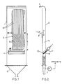
- Fig. 1 eine Aufrißdarstellung des Mehrkanal-Zick-Zack-Sichters,
- Fig. 2 eine Seitenansicht und
- Fig. 3 die Luftzuführung zu den Sichterkanälen.
- 1 is an elevation of the multi-channel zigzag sifter;
- Fig. 2 is a side view and
- Fig. 3 shows the air supply to the classifier channels.
Der in Fig. 1 schematisch dargestellte Zick-Zack-Sichter besteht aus einem Gehäuse 1 mit einem Sammelraum 2 für das ausgetragene Gut mit der Wunschkorngröße, dem Zick-Zack-Sichterpaket und dem Luftverteilungskanal 4 für die Zuführung der Sichtluft. Das Zick-Zack-Sichterpaket besteht aus einer Vielzahl vertikal angeordneter, strömungstechnisch parallel geschalteter zickzackförmiger Kanäle 5 mit aufgesetzten Rückführungsschächten 6. Durch die Rückführungsschächte 6 wird das Unterkorn gegebenenfalls in ein Gutbett zurückgeschleudert. Sie können glatte oder zick-zack-förmig ausgebildete Kanalwände haben.The zigzag sifter shown schematically in Fig. 1 consists of a housing 1 with a
Zu diesem Zweck ist am oberen Ende des Rückführungsschachtes 6 eine Öffnung 7 vorhanden (siehe Fig. 2). Das zu sichtende Gut wird über die Eintragsöffnung 8 am oberen Ende der Sichterkanäle 5 zugeführt. An ihrem unteren Ende sind die Kanäle 5, wie nachfolgend noch genauer beschrieben wird, mit dem Luftverteilungskanal 4 für die Zuführung der Sichtluft verbunden. Jeder Kanal 5 ist, wie aus Fig. 2 ersichtlich, mit einem Luftverteilungsrohr 9 ausgestattet, das z.B. unter einem Winkel von α = 45° gegen die Horizontale geneigt ist und an seiner Oberfläche Perforationen 10 für einen gleichmäßigen Luftaustritt aufweist. Die Sichtluft wird dem Luftverteilungsrohr über eine mit Schallgeschwindigkeit durchströmte Blende oder Drossel (Schalldrossel) 11 zugeführt (siehe auch Beschreibung zur Fig. 3). Unterhalb der Luftverteilungsrohre 9 sind zickzackförmige Engstellen (Labyrinthe) 12 angeordnet, deren Durchmesser nur geringfügig größer ist als der Durchmesser des auszutragenden gesichteten Guts (Wunschkorndurchmesser). Durch das Labyrinth 12 kann also das Grobgutkorn gerade noch ungehindert aus dem Sichtkanal 5 herausfallen. Das Labyrinth 12 dient letzten Endes zur Verbesserung der Trennschärfe, wenn in den Sichterkanälen 5 mit einer unterschiedlichen Feststoffbeladung zu rechnen ist und daraus unterschiedliche Druckverteilungen resultieren. Die Engstellen 12 wirken Strömungsinstabilitäten entgegen, die sich aus solchen unterschiedlichen Druckverteilungen ergeben.For this purpose, an opening 7 is provided at the upper end of the return shaft 6 (see FIG. 2). The material to be sifted is fed through the entry opening 8 at the upper end of the
Aus Fig. 3 ist die Luftzuführung zur den Luftverteilungsrohren 9 ersichtlich. Aus dem Luftverteilungskanal 4 werden parallel die Sichtluftströme für die Kanäle 5 abgezweigt. Durch die in den einzelnen Zuführungen zu den Luftverteilungsrohren 9 angeordneten Schalldrosseln 11 wird erreicht, daß in jedes Luftverteilungsrohr 9 unabhängig vom Druck hinter der Schalldrossel eine Luftmenge einströmt, die nur vom Querschnitt und dem Druck vor der Schalldrossel bestimmt wird. Bei gleichem Querschnitt der Schalldrosseln ist also auch der Luftdurchsatz für alle Sichterkanäle gleich groß.The air supply to the air distribution pipes 9 can be seen from FIG. 3. The sifting air flows for the
Um den Sichtluftdurchsatz aller Kanäle 5 gleichmäßig zu variieren, braucht also nur der Druck im Luftverteilungskanal 4 entsprechend geändert zu werden.In order to vary the visible air throughput of all
Um sicherzustellen, daß durch den Sammelraum 2 unterhalb der Querschnittsverengung 12 weder Luft in die Kanäle ein- noch ausströmt, ist die Absaugung für die Sichterabluft mit einer Regeleinrichtung versehen, die dafür sorgt, daß im Sammelraum 2 Umgebungsdruck herrscht. Aus dem Sammelraum 2 wird das gesichtete Gut durch eine Zellenradschleuse 13 ausgetragen.In order to ensure that neither air flows into or out of the channels through the
Claims (6)
Applications Claiming Priority (2)
| Application Number | Priority Date | Filing Date | Title |
|---|---|---|---|
| DE3808116A DE3808116A1 (en) | 1988-03-11 | 1988-03-11 | ZIGZAG SIFTER |
| DE3808116 | 1988-03-11 |
Publications (3)
| Publication Number | Publication Date |
|---|---|
| EP0332031A2 true EP0332031A2 (en) | 1989-09-13 |
| EP0332031A3 EP0332031A3 (en) | 1991-07-31 |
| EP0332031B1 EP0332031B1 (en) | 1994-01-26 |
Family
ID=6349469
Family Applications (1)
| Application Number | Title | Priority Date | Filing Date |
|---|---|---|---|
| EP89103544A Expired - Lifetime EP0332031B1 (en) | 1988-03-11 | 1989-03-01 | Zigzag sifter |
Country Status (4)
| Country | Link |
|---|---|
| US (1) | US4931174A (en) |
| EP (1) | EP0332031B1 (en) |
| JP (1) | JP2753848B2 (en) |
| DE (2) | DE3808116A1 (en) |
Cited By (3)
| Publication number | Priority date | Publication date | Assignee | Title |
|---|---|---|---|---|
| US5961707A (en) * | 1997-04-09 | 1999-10-05 | Haarmann & Reimer Gmbh | Alcohol-containing granules |
| EP1958520A2 (en) | 2007-02-09 | 2008-08-20 | Symrise GmbH & Co. KG | Fluidised bed granulate with high fruit content |
| CN110074448A (en) * | 2019-06-19 | 2019-08-02 | 常德烟草机械有限责任公司 | A kind of stem sorting unit |
Families Citing this family (7)
| Publication number | Priority date | Publication date | Assignee | Title |
|---|---|---|---|---|
| US5213820A (en) * | 1984-02-27 | 1993-05-25 | Bayer Aktiengesellschaft | Process and device for fluidized bed spray granulation |
| DE4200821A1 (en) * | 1992-01-15 | 1993-07-22 | Bayer Ag | TASTE-MASKED PHARMACEUTICAL AGENTS |
| DE4304405A1 (en) * | 1993-02-15 | 1994-08-18 | Bayer Ag | Process for continuous fluidized bed agglomeration |
| US6213307B1 (en) * | 1995-11-15 | 2001-04-10 | Grana Inc. | Fluid-bed cleaner and grades sorter for particle form materials |
| ATE497353T1 (en) * | 2003-06-19 | 2011-02-15 | Hauni Maschinenbau Ag | VIEWING MEANS FOR VIEWING A PRODUCT STREAM WITHIN A DISTRIBUTION DEVICE |
| DE102010007593A1 (en) * | 2010-02-04 | 2011-08-04 | Hauni Maschinenbau AG, 21033 | Viewing means for viewing a product flow within a distributor device |
| DE102013215062A1 (en) * | 2013-07-31 | 2015-02-05 | Krones Ag | Zig-zag separator for separating separating material, for example plastic flakes, and method for separating separating material, for example plastic flakes, by means of a zig-zag separator |
Citations (7)
| Publication number | Priority date | Publication date | Assignee | Title |
|---|---|---|---|---|
| US1861248A (en) * | 1930-01-03 | 1932-05-31 | Albert H Stebbins | Air classifier |
| DE1135841B (en) * | 1960-06-09 | 1962-09-06 | Dr Theodor Eder | Method and device for separating granular material into at least two end fractions |
| CH419810A (en) * | 1961-06-15 | 1966-08-31 | Alpine Ag | Process for the sifting of bulk material, such as grain crops, seeds and sifting system for carrying out the same |
| US3437202A (en) * | 1966-04-06 | 1969-04-08 | Alpine Ag | Flow channel for zigzag classifiers |
| US3929628A (en) * | 1973-08-16 | 1975-12-30 | Vista Chemical & Fiber Product | Apparatus for reducing preconditioned garbage to a clinkerless combustible |
| EP0163836A1 (en) * | 1984-04-07 | 1985-12-11 | Bayer Ag | Process and apparatus for the production of granules |
| FR2602699A1 (en) * | 1986-08-13 | 1988-02-19 | Uralsky Politekhn Inst | PNEUMATIC CLASSIFIER FOR THE SEPARATION OF PULVERULENT MATERIALS BY GRAVITY |
Family Cites Families (11)
| Publication number | Priority date | Publication date | Assignee | Title |
|---|---|---|---|---|
| NL136425C (en) * | 1966-07-11 | |||
| US3876419A (en) * | 1970-07-06 | 1975-04-08 | Lev Petrovich Brusov | Method of thermal and chemical treatment of solids of starting material not over 0.5 mm in size |
| US3925198A (en) * | 1975-01-29 | 1975-12-09 | Univ Utah | Apparatus and method of air classifying municipal solid wastes |
| DE2641068A1 (en) * | 1976-09-11 | 1978-03-16 | Alpine Ag | Air sifter for granular material - uses settling tank for conveying channels and removal of oversized particles |
| DE2804548A1 (en) * | 1978-02-03 | 1979-08-09 | Krauss Maffei Ag | Wet paper separation from refuse - uses stream of hot air introduced at refuse entry end with subsequent sifting |
| US4235707A (en) * | 1979-04-09 | 1980-11-25 | Burke, Davoud & Associates | Method and apparatus for treating solid municipal refuse and other cellulose containing material |
| JPS5616227U (en) * | 1979-07-11 | 1981-02-12 | ||
| SU906633A1 (en) * | 1980-06-20 | 1982-02-23 | Всесоюзный Научно-Исследовательский Институт Деревообрабатывающей Промышленности | Apparatus for sorting wooden particles |
| SU1265002A1 (en) * | 1984-02-03 | 1986-10-23 | Уральский политехнический институт им.С.М.Кирова | Pneumatic multicolumn classifier |
| SU1268212A1 (en) * | 1985-06-17 | 1986-11-07 | Научно-исследовательский институт прикладной математики и механики при Томском государственном университете | Air separator |
| JPS6311067A (en) * | 1987-06-25 | 1988-01-18 | Victor Co Of Japan Ltd | Dc high voltage generating device |
-
1988
- 1988-03-11 DE DE3808116A patent/DE3808116A1/en not_active Withdrawn
-
1989
- 1989-02-27 US US07/316,368 patent/US4931174A/en not_active Expired - Lifetime
- 1989-03-01 DE DE89103544T patent/DE58906793D1/en not_active Expired - Lifetime
- 1989-03-01 EP EP89103544A patent/EP0332031B1/en not_active Expired - Lifetime
- 1989-03-10 JP JP1056571A patent/JP2753848B2/en not_active Expired - Fee Related
Patent Citations (7)
| Publication number | Priority date | Publication date | Assignee | Title |
|---|---|---|---|---|
| US1861248A (en) * | 1930-01-03 | 1932-05-31 | Albert H Stebbins | Air classifier |
| DE1135841B (en) * | 1960-06-09 | 1962-09-06 | Dr Theodor Eder | Method and device for separating granular material into at least two end fractions |
| CH419810A (en) * | 1961-06-15 | 1966-08-31 | Alpine Ag | Process for the sifting of bulk material, such as grain crops, seeds and sifting system for carrying out the same |
| US3437202A (en) * | 1966-04-06 | 1969-04-08 | Alpine Ag | Flow channel for zigzag classifiers |
| US3929628A (en) * | 1973-08-16 | 1975-12-30 | Vista Chemical & Fiber Product | Apparatus for reducing preconditioned garbage to a clinkerless combustible |
| EP0163836A1 (en) * | 1984-04-07 | 1985-12-11 | Bayer Ag | Process and apparatus for the production of granules |
| FR2602699A1 (en) * | 1986-08-13 | 1988-02-19 | Uralsky Politekhn Inst | PNEUMATIC CLASSIFIER FOR THE SEPARATION OF PULVERULENT MATERIALS BY GRAVITY |
Cited By (3)
| Publication number | Priority date | Publication date | Assignee | Title |
|---|---|---|---|---|
| US5961707A (en) * | 1997-04-09 | 1999-10-05 | Haarmann & Reimer Gmbh | Alcohol-containing granules |
| EP1958520A2 (en) | 2007-02-09 | 2008-08-20 | Symrise GmbH & Co. KG | Fluidised bed granulate with high fruit content |
| CN110074448A (en) * | 2019-06-19 | 2019-08-02 | 常德烟草机械有限责任公司 | A kind of stem sorting unit |
Also Published As
| Publication number | Publication date |
|---|---|
| EP0332031A3 (en) | 1991-07-31 |
| EP0332031B1 (en) | 1994-01-26 |
| JP2753848B2 (en) | 1998-05-20 |
| DE58906793D1 (en) | 1994-03-10 |
| US4931174A (en) | 1990-06-05 |
| DE3808116A1 (en) | 1989-09-21 |
| JPH01274880A (en) | 1989-11-02 |
Similar Documents
| Publication | Publication Date | Title |
|---|---|---|
| AT398915B (en) | METHOD FOR SEPARATING A MIXTURE OF SOLID PARTICLES IN INDIVIDUAL FRACTIONS, AND SYSTEM FOR IMPLEMENTING THE METHOD | |
| EP1987894A2 (en) | Screening machine | |
| EP2465617B1 (en) | Method and device for separating fine particles from granulate bulk goods in a pipe | |
| EP0332031B1 (en) | Zigzag sifter | |
| EP1287911B1 (en) | Classifier for granular material | |
| DE112016000194B4 (en) | Wind tunnel circulation sighting device for bulk material | |
| DE3404093C2 (en) | ||
| DE3626053C2 (en) | ||
| WO2018011430A1 (en) | Scattering installation and method for producing a mat of scattered material during the course of the production of material panels | |
| DE3209049A1 (en) | Apparatus for separating light particles from solid bulk material | |
| DE3310709C2 (en) | ||
| DE2450685A1 (en) | DEVICE FOR THE PRODUCTION OF A FLEECE | |
| DE102017124063A1 (en) | Scattering system and method for producing a spreading material mat in the course of the production of material plates | |
| DE2710543C2 (en) | ||
| DE3626044C2 (en) | ||
| DE102012109645B4 (en) | sifter | |
| DE3102167A1 (en) | Device for splitting a fluid or fluidised main flow between a plurality of secondary lines | |
| WO2001039899A1 (en) | Conical sifter and method for sifting bulk material which cannot be poured easily or at all | |
| DE1507686B1 (en) | Riser air separator | |
| DE202010004167U1 (en) | Fluidized bed classifier | |
| DE102009007944A1 (en) | Device for distributing free-flowing material to single-or multilayered material web, has wind distributing chamber whose air space is variably adjusted, and separated rough-material particles are moved on material non-woven support | |
| DE1532243B1 (en) | Method and device for conveying tobacco | |
| DE202012101573U1 (en) | Device for separating dust particles from larger bulk particles | |
| DE2444378C3 (en) | Method and device for sifting granular material in a cross-flow | |
| DE1507685B1 (en) | Feeding device for a riser pipe separator |
Legal Events
| Date | Code | Title | Description |
|---|---|---|---|
| PUAI | Public reference made under article 153(3) epc to a published international application that has entered the european phase |
Free format text: ORIGINAL CODE: 0009012 |
|
| 17P | Request for examination filed |
Effective date: 19890301 |
|
| AK | Designated contracting states |
Kind code of ref document: A2 Designated state(s): BE CH DE FR GB IT LI NL |
|
| PUAL | Search report despatched |
Free format text: ORIGINAL CODE: 0009013 |
|
| AK | Designated contracting states |
Kind code of ref document: A3 Designated state(s): BE CH DE FR GB IT LI NL |
|
| 17Q | First examination report despatched |
Effective date: 19920824 |
|
| GRAA | (expected) grant |
Free format text: ORIGINAL CODE: 0009210 |
|
| AK | Designated contracting states |
Kind code of ref document: B1 Designated state(s): BE CH DE FR GB IT LI NL |
|
| REF | Corresponds to: |
Ref document number: 58906793 Country of ref document: DE Date of ref document: 19940310 |
|
| ITF | It: translation for a ep patent filed |
Owner name: ING. C. GREGORJ S.P.A. |
|
| ET | Fr: translation filed | ||
| GBT | Gb: translation of ep patent filed (gb section 77(6)(a)/1977) |
Effective date: 19940311 |
|
| K2C3 | Correction of patent specification (complete document) published |
Effective date: 19940126 |
|
| PLBE | No opposition filed within time limit |
Free format text: ORIGINAL CODE: 0009261 |
|
| STAA | Information on the status of an ep patent application or granted ep patent |
Free format text: STATUS: NO OPPOSITION FILED WITHIN TIME LIMIT |
|
| 26N | No opposition filed | ||
| REG | Reference to a national code |
Ref country code: GB Ref legal event code: IF02 |
|
| REG | Reference to a national code |
Ref country code: CH Ref legal event code: PFA Owner name: BAYER AKTIENGESELLSCHAFT Free format text: BAYER AKTIENGESELLSCHAFT# #D-51368 LEVERKUSEN (DE) -TRANSFER TO- BAYER AKTIENGESELLSCHAFT# #D-51368 LEVERKUSEN (DE) |
|
| PGFP | Annual fee paid to national office [announced via postgrant information from national office to epo] |
Ref country code: CH Payment date: 20080228 Year of fee payment: 20 |
|
| PGFP | Annual fee paid to national office [announced via postgrant information from national office to epo] |
Ref country code: NL Payment date: 20080229 Year of fee payment: 20 Ref country code: GB Payment date: 20080227 Year of fee payment: 20 Ref country code: IT Payment date: 20080327 Year of fee payment: 20 |
|
| PGFP | Annual fee paid to national office [announced via postgrant information from national office to epo] |
Ref country code: FR Payment date: 20080311 Year of fee payment: 20 Ref country code: DE Payment date: 20080226 Year of fee payment: 20 |
|
| PGFP | Annual fee paid to national office [announced via postgrant information from national office to epo] |
Ref country code: BE Payment date: 20080522 Year of fee payment: 20 |
|
| REG | Reference to a national code |
Ref country code: CH Ref legal event code: PL |
|
| REG | Reference to a national code |
Ref country code: GB Ref legal event code: PE20 Expiry date: 20090228 |
|
| BE20 | Be: patent expired |
Owner name: *BAYER A.G. Effective date: 20090301 |
|
| NLV7 | Nl: ceased due to reaching the maximum lifetime of a patent |
Effective date: 20090301 |
|
| PG25 | Lapsed in a contracting state [announced via postgrant information from national office to epo] |
Ref country code: NL Free format text: LAPSE BECAUSE OF EXPIRATION OF PROTECTION Effective date: 20090301 |
|
| PG25 | Lapsed in a contracting state [announced via postgrant information from national office to epo] |
Ref country code: GB Free format text: LAPSE BECAUSE OF EXPIRATION OF PROTECTION Effective date: 20090228 |