EP0332020A2 - Dispositif de commande de roue - Google Patents
Dispositif de commande de roue Download PDFInfo
- Publication number
- EP0332020A2 EP0332020A2 EP89103477A EP89103477A EP0332020A2 EP 0332020 A2 EP0332020 A2 EP 0332020A2 EP 89103477 A EP89103477 A EP 89103477A EP 89103477 A EP89103477 A EP 89103477A EP 0332020 A2 EP0332020 A2 EP 0332020A2
- Authority
- EP
- European Patent Office
- Prior art keywords
- guide
- wheel
- wheel carrier
- arrangement
- axis
- Prior art date
- Legal status (The legal status is an assumption and is not a legal conclusion. Google has not performed a legal analysis and makes no representation as to the accuracy of the status listed.)
- Withdrawn
Links
- 238000006073 displacement reaction Methods 0.000 claims description 4
- 239000002184 metal Substances 0.000 claims description 4
- 239000006096 absorbing agent Substances 0.000 description 4
- 230000035939 shock Effects 0.000 description 4
- 230000005540 biological transmission Effects 0.000 description 2
- 230000006835 compression Effects 0.000 description 2
- 238000007906 compression Methods 0.000 description 2
- 230000008878 coupling Effects 0.000 description 2
- 238000010168 coupling process Methods 0.000 description 2
- 238000005859 coupling reaction Methods 0.000 description 2
- 239000000725 suspension Substances 0.000 description 2
- 230000015572 biosynthetic process Effects 0.000 description 1
- 238000011161 development Methods 0.000 description 1
- 230000018109 developmental process Effects 0.000 description 1
- 230000000717 retained effect Effects 0.000 description 1
Images

Classifications
-
- B—PERFORMING OPERATIONS; TRANSPORTING
- B62—LAND VEHICLES FOR TRAVELLING OTHERWISE THAN ON RAILS
- B62D—MOTOR VEHICLES; TRAILERS
- B62D7/00—Steering linkage; Stub axles or their mountings
- B62D7/06—Steering linkage; Stub axles or their mountings for individually-pivoted wheels, e.g. on king-pins
-
- B—PERFORMING OPERATIONS; TRANSPORTING
- B60—VEHICLES IN GENERAL
- B60G—VEHICLE SUSPENSION ARRANGEMENTS
- B60G17/00—Resilient suspensions having means for adjusting the spring or vibration-damper characteristics, for regulating the distance between a supporting surface and a sprung part of vehicle or for locking suspension during use to meet varying vehicular or surface conditions, e.g. due to speed or load
- B60G17/015—Resilient suspensions having means for adjusting the spring or vibration-damper characteristics, for regulating the distance between a supporting surface and a sprung part of vehicle or for locking suspension during use to meet varying vehicular or surface conditions, e.g. due to speed or load the regulating means comprising electric or electronic elements
- B60G17/019—Resilient suspensions having means for adjusting the spring or vibration-damper characteristics, for regulating the distance between a supporting surface and a sprung part of vehicle or for locking suspension during use to meet varying vehicular or surface conditions, e.g. due to speed or load the regulating means comprising electric or electronic elements characterised by the type of sensor or the arrangement thereof
- B60G17/01933—Velocity, e.g. relative velocity-displacement sensors
-
- B—PERFORMING OPERATIONS; TRANSPORTING
- B62—LAND VEHICLES FOR TRAVELLING OTHERWISE THAN ON RAILS
- B62D—MOTOR VEHICLES; TRAILERS
- B62D7/00—Steering linkage; Stub axles or their mountings
- B62D7/18—Steering knuckles; King pins
-
- B—PERFORMING OPERATIONS; TRANSPORTING
- B60—VEHICLES IN GENERAL
- B60G—VEHICLE SUSPENSION ARRANGEMENTS
- B60G2204/00—Indexing codes related to suspensions per se or to auxiliary parts
- B60G2204/10—Mounting of suspension elements
- B60G2204/11—Mounting of sensors thereon
-
- B—PERFORMING OPERATIONS; TRANSPORTING
- B60—VEHICLES IN GENERAL
- B60G—VEHICLE SUSPENSION ARRANGEMENTS
- B60G2204/00—Indexing codes related to suspensions per se or to auxiliary parts
- B60G2204/40—Auxiliary suspension parts; Adjustment of suspensions
- B60G2204/423—Rails, tubes, or the like, for guiding the movement of suspension elements
- B60G2204/4232—Sliding mounts
-
- B—PERFORMING OPERATIONS; TRANSPORTING
- B60—VEHICLES IN GENERAL
- B60G—VEHICLE SUSPENSION ARRANGEMENTS
- B60G2300/00—Indexing codes relating to the type of vehicle
- B60G2300/02—Trucks; Load vehicles
- B60G2300/026—Heavy duty trucks
-
- B—PERFORMING OPERATIONS; TRANSPORTING
- B60—VEHICLES IN GENERAL
- B60G—VEHICLE SUSPENSION ARRANGEMENTS
- B60G2300/00—Indexing codes relating to the type of vehicle
- B60G2300/36—Independent Multi-axle long vehicles
-
- B—PERFORMING OPERATIONS; TRANSPORTING
- B60—VEHICLES IN GENERAL
- B60G—VEHICLE SUSPENSION ARRANGEMENTS
- B60G2400/00—Indexing codes relating to detected, measured or calculated conditions or factors
- B60G2400/25—Stroke; Height; Displacement
- B60G2400/252—Stroke; Height; Displacement vertical
-
- B—PERFORMING OPERATIONS; TRANSPORTING
- B60—VEHICLES IN GENERAL
- B60G—VEHICLE SUSPENSION ARRANGEMENTS
- B60G2401/00—Indexing codes relating to the type of sensors based on the principle of their operation
- B60G2401/17—Magnetic/Electromagnetic
- B60G2401/172—Hall effect
Definitions
- the invention relates to a wheel guide arrangement with a spring strut, consisting of a guide housing fastened to the chassis of a vehicle and a support element which can be moved axially and rotatably therewith, with a wheel carrier fastened to the support element and with a guide element.
- a wheel guide arrangement is provided for a single wheel, which, however, can optionally also be designed as a twin-wheeled twin wheel.
- a steering lever is considered as a guide element, which is held by a steering linkage or - in the case of non-steered wheels - by a handlebar articulated at a fixed point on the chassis.
- the steering lever can have several articulation points, e.g. for the steering linkage coming from the steering gear, for the tie rod leading to the opposite wheel and for a coupling rod leading to a leading or trailing wheel.
- the support element can be hydraulically cushioned axially against the guide housing attached to the chassis by a pressure accumulator, pneumatically and / or by mechanical spring elements.
- the axis of the strut generally has a spread of a few degrees for better tracking of the wheels, i.e. the axis of the shock absorber is slightly further down from the imaginary longitudinal median plane than at the top.
- the left and right steerable wheels of an (imaginary) "axle” are connected to each other by a tie rod. If both wheels spring out at the same time, the distance between the pivot points of the steering levers increases. Since the length of the tie rod cannot be changed, there is a divergence or convergence of the wheels, i.e. deflection or compression, depending on the position of the trapezoid (tie rod arranged at the front or rear). these assume a diverging or converging position.
- the invention has for its object to design the steering of the wheel guide assembly so that the steering error described is avoided during rebound and compression.
- the guide element is rotatably mounted on the outside of the guide housing and is connected to the wheel carrier via a rotary driver arrangement that is free of force and form-fit in the axial direction.
- the driver arrangement consists of a lever articulated on the steering lever and the wheel carrier at two points, which are also connected together. When viewed from the side, they form - with the same geometric length - a side half of a height-adjustable rhombus.
- the transmission of torques required for tracking from the steering lever to the wheel carrier is achieved by the axial articulation of the levers which is effective over a certain width.
- the displacement sensor according to claim 5 preferably consists of a metal part which is aligned parallel to the axis of the suspension strut and is connected to the wheel body, and at least one pair of switching elements arranged on the guide element.
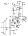
- the guide housing 1 of a shock absorber 2 is fastened to a vehicle frame 3, the axis A of the shock absorber is inclined at a spread angle ⁇ against the vertical.
- a support element 4 is rotatably and axially movable about the axis A.
- the support element 4 is designed as a plunger, the cylinder chamber 5 located above it being filled with a pressure medium which is connected via a line 6 to a pressure supply (not shown) with a pressure accumulator.
- the design of the interior of the strut 2 is not the subject of the present application.
- the cylindrical support element 4 is provided at the bottom with a flange 7 to which a wheel carrier 8 is screwed for receiving a wheel, of which only the wheel hub 9 is shown in the drawing.
- a two-part ring 10 is rotatably mounted on the outside, to which a steering lever 11 is screwed as a guide element.
- This steering lever 11 can - seen in plan view - be formed in several parts and have a plurality of pivot pins 12, to each of which a steering linkage 14 or (not shown) a tie rod or a coupling rod leading to a leading or trailing wheel is articulated.
- the steering lever 11 has two downwardly facing bearing points 15, to which an upper V-shaped lever or link 17 is articulated.
- the wheel carrier 8 also has two bearing points 18 to which a further, lower V-shaped lever or handlebar 20 is articulated.
- the free ends of the two levers 17, 20 form a common hinge joint 21.
- the double lever arrangement consisting of the levers 17, 20 does not transmit any forces in the direction of the axis A of the spring strut 2.
- the double lever arrangement 17, 20 generates torques from the steering lever 11 to the wheel carrier 8 or vice versa at every height position of the support element 4 relative to the guide housing 1 transfer.
- the double lever arrangement 17, 20 thus functions as a rotary driver arrangement that is forceless and formless in the axial direction.
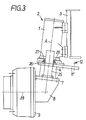
- a shield-shaped guide column 25 which extends parallel to the axis A and has a constant cross section in the form of e.g. attached to a ring section.
- This guide column 25 is guided through a corresponding recess 26 in the steering lever 11 'between two guide or pressure rollers 27, 28 attached to this steering lever.
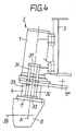
- the rotary driver arrangement has two guide bolts 31, 32 on which are attached to the flange 7 of the support element 4 via a common support 33.
- the guide bolts 31, 32 are guided in bushings 35 fastened in the steering lever 11 ⁇ and are connected to one another for stability by a common upper yoke 37.
- the function of the torque transmission is the same as in the exemplary embodiment according to FIG. 3.
- the elements of the rotary driver arrangement described in connection with FIGS. 1 to 4 can be arranged on the spring strut 2 both in the front and in the rear, as seen in the direction of travel.
- the volume of the hydraulic medium in the cylinder or pressure chamber 5 of the spring strut 2 is dimensioned accordingly via the pressure.
- a change in the height or level of the vehicle frame 3 can be equated with the change in the relative position between the guide housing 1 and the support element 4 with close approximation.
- the guide column 25 or the guide bolts 31, 32 or, if these are connected to a yoke 37, the yoke itself serve as a corresponding metal part.
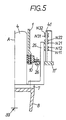
- FIG. 5 shows a level measuring device in connection with the guide column 25.
- a bracket 41 attached to the steering lever 11 three pairs of proximity switches N11, N12 ... N31, N32 are shown. If a pair of proximity switches, e.g. N21, N22, the lower proximity switch N21 emits a signal due to the guide column 25 located in front of it and the upper proximity switch N22 does not emit a signal, the upper edge of the guide column 25 is located between these two proximity switches. If both proximity switches emit a signal, the upper edge of the guide column 25 is above this pair (in the exemplary embodiment shown in FIG. 5, the proximity switches N11, N12). If neither of the proximity switches of a pair emits a signal (in the exemplary embodiment shown in FIG.
- the proximity switches N31, N32), the upper edge of the guide column 25 is located below the pair.
- the level of the guide column 25 with respect to the steering lever 11 '- and thus also the level of the support element 4 with respect to the fixed housing 1 or the level between the wheel axis 39 and the chassis frame 3 - can thus be determined in predetermined stages and in a known manner via a Set or change the control loop.
Landscapes
- Engineering & Computer Science (AREA)
- Mechanical Engineering (AREA)
- Chemical & Material Sciences (AREA)
- Combustion & Propulsion (AREA)
- Transportation (AREA)
- Vehicle Body Suspensions (AREA)
- Steering-Linkage Mechanisms And Four-Wheel Steering (AREA)
Applications Claiming Priority (2)
| Application Number | Priority Date | Filing Date | Title |
|---|---|---|---|
| DE3807301A DE3807301A1 (de) | 1988-03-05 | 1988-03-05 | Radfuehrungsanordnung |
| DE3807301 | 1988-03-05 |
Publications (1)
| Publication Number | Publication Date |
|---|---|
| EP0332020A2 true EP0332020A2 (fr) | 1989-09-13 |
Family
ID=6348988
Family Applications (1)
| Application Number | Title | Priority Date | Filing Date |
|---|---|---|---|
| EP89103477A Withdrawn EP0332020A2 (fr) | 1988-03-05 | 1989-02-28 | Dispositif de commande de roue |
Country Status (4)
| Country | Link |
|---|---|
| EP (1) | EP0332020A2 (fr) |
| JP (1) | JPH01254474A (fr) |
| DE (1) | DE3807301A1 (fr) |
| FI (1) | FI890967A7 (fr) |
Cited By (4)
| Publication number | Priority date | Publication date | Assignee | Title |
|---|---|---|---|---|
| DE4131545A1 (de) * | 1991-09-21 | 1993-04-01 | Krupp Industrietech | Federbein fuer hydraulischen radantrieb |
| EP0544484A3 (en) * | 1991-11-27 | 1993-09-22 | Lord Corporation | System for controlling suspension deflection |
| NL1000836C2 (nl) * | 1995-07-18 | 1997-01-21 | Koninkl Nooteboom Trailers Bv | Wielstel en daarmee uitgerust voertuig. |
| WO2010020847A3 (fr) * | 2008-08-20 | 2010-04-22 | Agco Corporation | Ensembles suspensions avec contrôle des manœuvres en cas de choc |
Family Cites Families (2)
| Publication number | Priority date | Publication date | Assignee | Title |
|---|---|---|---|---|
| US4453734A (en) * | 1982-05-17 | 1984-06-12 | Mcghie James R | Steerable wheel suspension assembly |
| JP2587631B2 (ja) * | 1987-03-20 | 1997-03-05 | トキコ株式会社 | 車高調整装置 |
-
1988
- 1988-03-05 DE DE3807301A patent/DE3807301A1/de not_active Withdrawn
-
1989
- 1989-02-28 EP EP89103477A patent/EP0332020A2/fr not_active Withdrawn
- 1989-03-01 FI FI890967A patent/FI890967A7/fi not_active Application Discontinuation
- 1989-03-03 JP JP1050227A patent/JPH01254474A/ja active Pending
Cited By (8)
| Publication number | Priority date | Publication date | Assignee | Title |
|---|---|---|---|---|
| DE4131545A1 (de) * | 1991-09-21 | 1993-04-01 | Krupp Industrietech | Federbein fuer hydraulischen radantrieb |
| WO1993005969A1 (fr) * | 1991-09-21 | 1993-04-01 | Krupp Industrietechnik Gesellschaft Mit Beschränkter Haftung | Jambe de suspension pour commande hydraulique des roues |
| US5472071A (en) * | 1991-09-21 | 1995-12-05 | Krupp Industrietechnik Gesselschaft mit beschrankter Haftung | Shock-absorbing strut for hydraulic wheel-drive unit |
| CN1039683C (zh) * | 1991-09-21 | 1998-09-09 | 基德工业公司 | 液压车轮驱动减震支柱 |
| EP0544484A3 (en) * | 1991-11-27 | 1993-09-22 | Lord Corporation | System for controlling suspension deflection |
| NL1000836C2 (nl) * | 1995-07-18 | 1997-01-21 | Koninkl Nooteboom Trailers Bv | Wielstel en daarmee uitgerust voertuig. |
| WO2010020847A3 (fr) * | 2008-08-20 | 2010-04-22 | Agco Corporation | Ensembles suspensions avec contrôle des manœuvres en cas de choc |
| US8136824B2 (en) | 2008-08-20 | 2012-03-20 | Agco Corporation | Suspension assemblies with bump steer control |
Also Published As
| Publication number | Publication date |
|---|---|
| FI890967A0 (fi) | 1989-03-01 |
| DE3807301A1 (de) | 1989-09-14 |
| FI890967A7 (fi) | 1989-09-06 |
| JPH01254474A (ja) | 1989-10-11 |
Similar Documents
| Publication | Publication Date | Title |
|---|---|---|
| DE69934671T2 (de) | Verstellbare fahrzeugaufhängung | |
| DE4108164C2 (fr) | ||
| DE3928906C2 (de) | Federbeinaufhängung | |
| DE3035856C2 (fr) | ||
| DE3926665C2 (de) | Radaufhängung für Kraftfahrzeuge | |
| DE3403466C2 (fr) | ||
| DE2918605A1 (de) | Einzelradaufhaengung mittels uebereinander angeordneter fuehrungslenker | |
| DE19850136A1 (de) | Vorderradaufhängung für Kraftfahrzeuge | |
| DE3342355A1 (de) | Fahrzeugaufhaengung | |
| DE102015001864A1 (de) | Radaufhängung für einen Mobilkran sowie Mobilkran | |
| DE2703651B2 (de) | Einzelradaufhängung für die Hinterräder eines Kraftfahrzeugs | |
| DE69320325T2 (de) | Fahrzeugaufhängungssystem | |
| DE2249913A1 (de) | Radaufhaengung fuer kraftfahrzeuge | |
| DE60004214T2 (de) | Selbstlenkende achse | |
| DE4334742C2 (de) | Deaktivierbare Achslenkung | |
| DE3912520B4 (de) | Hinterachse für ein Kraftfahrzeug | |
| DE102016003885A1 (de) | Radaufhängung für einen Mobilkran | |
| EP0332020A2 (fr) | Dispositif de commande de roue | |
| DE102012220490A1 (de) | Unabhängige Hinterradaufhängung eines Kraftfahrzeugs | |
| DE102018207616B4 (de) | Radaufhängung für ein Kraftfahrzeug | |
| EP0313962A1 (fr) | Essieu directeur | |
| DE19611114B4 (de) | Radaufhängung einer ungelenkten Kraftfahrzeugachse | |
| DE2011371C2 (de) | Einzelradaufhängung für einzeln antreibbare lenkbare Fahrzeugräder | |
| DD244316A5 (de) | Verankerungssystem fuer starre achsen von fahrzeugen mit staarr an dem fahrgestell befestigten, vertikal beweglichen aufhaengungen | |
| DE1069012B (fr) |
Legal Events
| Date | Code | Title | Description |
|---|---|---|---|
| PUAI | Public reference made under article 153(3) epc to a published international application that has entered the european phase |
Free format text: ORIGINAL CODE: 0009012 |
|
| AK | Designated contracting states |
Kind code of ref document: A2 Designated state(s): DE ES FR GB IT |
|
| 18W | Application withdrawn |
Withdrawal date: 19900608 |
|
| STAA | Information on the status of an ep patent application or granted ep patent |
Free format text: STATUS: THE APPLICATION HAS BEEN WITHDRAWN |
|
| R18W | Application withdrawn (corrected) |
Effective date: 19900608 |