EP0331958A2 - Hydraulic control device - Google Patents
Hydraulic control device Download PDFInfo
- Publication number
- EP0331958A2 EP0331958A2 EP19890102903 EP89102903A EP0331958A2 EP 0331958 A2 EP0331958 A2 EP 0331958A2 EP 19890102903 EP19890102903 EP 19890102903 EP 89102903 A EP89102903 A EP 89102903A EP 0331958 A2 EP0331958 A2 EP 0331958A2
- Authority
- EP
- European Patent Office
- Prior art keywords
- control
- line
- pressure
- spring
- consumer
- Prior art date
- Legal status (The legal status is an assumption and is not a legal conclusion. Google has not performed a legal analysis and makes no representation as to the accuracy of the status listed.)
- Granted
Links
Images
Classifications
-
- F—MECHANICAL ENGINEERING; LIGHTING; HEATING; WEAPONS; BLASTING
- F15—FLUID-PRESSURE ACTUATORS; HYDRAULICS OR PNEUMATICS IN GENERAL
- F15B—SYSTEMS ACTING BY MEANS OF FLUIDS IN GENERAL; FLUID-PRESSURE ACTUATORS, e.g. SERVOMOTORS; DETAILS OF FLUID-PRESSURE SYSTEMS, NOT OTHERWISE PROVIDED FOR
- F15B13/00—Details of servomotor systems ; Valves for servomotor systems
- F15B13/02—Fluid distribution or supply devices characterised by their adaptation to the control of servomotors
- F15B13/04—Fluid distribution or supply devices characterised by their adaptation to the control of servomotors for use with a single servomotor
- F15B13/0401—Valve members; Fluid interconnections therefor
- F15B13/0402—Valve members; Fluid interconnections therefor for linearly sliding valves, e.g. spool valves
- F15B13/0403—Valve members; Fluid interconnections therefor for linearly sliding valves, e.g. spool valves a secondary valve member sliding within the main spool, e.g. for regeneration flow
-
- E—FIXED CONSTRUCTIONS
- E02—HYDRAULIC ENGINEERING; FOUNDATIONS; SOIL SHIFTING
- E02F—DREDGING; SOIL-SHIFTING
- E02F9/00—Component parts of dredgers or soil-shifting machines, not restricted to one of the kinds covered by groups E02F3/00 - E02F7/00
- E02F9/20—Drives; Control devices
- E02F9/22—Hydraulic or pneumatic drives
- E02F9/2221—Control of flow rate; Load sensing arrangements
- E02F9/2225—Control of flow rate; Load sensing arrangements using pressure-compensating valves
-
- F—MECHANICAL ENGINEERING; LIGHTING; HEATING; WEAPONS; BLASTING
- F15—FLUID-PRESSURE ACTUATORS; HYDRAULICS OR PNEUMATICS IN GENERAL
- F15B—SYSTEMS ACTING BY MEANS OF FLUIDS IN GENERAL; FLUID-PRESSURE ACTUATORS, e.g. SERVOMOTORS; DETAILS OF FLUID-PRESSURE SYSTEMS, NOT OTHERWISE PROVIDED FOR
- F15B11/00—Servomotor systems without provision for follow-up action; Circuits therefor
- F15B11/16—Servomotor systems without provision for follow-up action; Circuits therefor with two or more servomotors
- F15B11/161—Servomotor systems without provision for follow-up action; Circuits therefor with two or more servomotors with sensing of servomotor demand or load
- F15B11/165—Servomotor systems without provision for follow-up action; Circuits therefor with two or more servomotors with sensing of servomotor demand or load for adjusting the pump output or bypass in response to demand
-
- F—MECHANICAL ENGINEERING; LIGHTING; HEATING; WEAPONS; BLASTING
- F15—FLUID-PRESSURE ACTUATORS; HYDRAULICS OR PNEUMATICS IN GENERAL
- F15B—SYSTEMS ACTING BY MEANS OF FLUIDS IN GENERAL; FLUID-PRESSURE ACTUATORS, e.g. SERVOMOTORS; DETAILS OF FLUID-PRESSURE SYSTEMS, NOT OTHERWISE PROVIDED FOR
- F15B13/00—Details of servomotor systems ; Valves for servomotor systems
- F15B13/02—Fluid distribution or supply devices characterised by their adaptation to the control of servomotors
- F15B13/04—Fluid distribution or supply devices characterised by their adaptation to the control of servomotors for use with a single servomotor
- F15B13/0416—Fluid distribution or supply devices characterised by their adaptation to the control of servomotors for use with a single servomotor with means or adapted for load sensing
-
- F—MECHANICAL ENGINEERING; LIGHTING; HEATING; WEAPONS; BLASTING
- F15—FLUID-PRESSURE ACTUATORS; HYDRAULICS OR PNEUMATICS IN GENERAL
- F15B—SYSTEMS ACTING BY MEANS OF FLUIDS IN GENERAL; FLUID-PRESSURE ACTUATORS, e.g. SERVOMOTORS; DETAILS OF FLUID-PRESSURE SYSTEMS, NOT OTHERWISE PROVIDED FOR
- F15B2211/00—Circuits for servomotor systems
- F15B2211/20—Fluid pressure source, e.g. accumulator or variable axial piston pump
- F15B2211/205—Systems with pumps
-
- F—MECHANICAL ENGINEERING; LIGHTING; HEATING; WEAPONS; BLASTING
- F15—FLUID-PRESSURE ACTUATORS; HYDRAULICS OR PNEUMATICS IN GENERAL
- F15B—SYSTEMS ACTING BY MEANS OF FLUIDS IN GENERAL; FLUID-PRESSURE ACTUATORS, e.g. SERVOMOTORS; DETAILS OF FLUID-PRESSURE SYSTEMS, NOT OTHERWISE PROVIDED FOR
- F15B2211/00—Circuits for servomotor systems
- F15B2211/30—Directional control
- F15B2211/305—Directional control characterised by the type of valves
- F15B2211/30505—Non-return valves, i.e. check valves
-
- F—MECHANICAL ENGINEERING; LIGHTING; HEATING; WEAPONS; BLASTING
- F15—FLUID-PRESSURE ACTUATORS; HYDRAULICS OR PNEUMATICS IN GENERAL
- F15B—SYSTEMS ACTING BY MEANS OF FLUIDS IN GENERAL; FLUID-PRESSURE ACTUATORS, e.g. SERVOMOTORS; DETAILS OF FLUID-PRESSURE SYSTEMS, NOT OTHERWISE PROVIDED FOR
- F15B2211/00—Circuits for servomotor systems
- F15B2211/30—Directional control
- F15B2211/305—Directional control characterised by the type of valves
- F15B2211/30525—Directional control valves, e.g. 4/3-directional control valve
- F15B2211/3053—In combination with a pressure compensating valve
- F15B2211/30535—In combination with a pressure compensating valve the pressure compensating valve is arranged between pressure source and directional control valve
-
- F—MECHANICAL ENGINEERING; LIGHTING; HEATING; WEAPONS; BLASTING
- F15—FLUID-PRESSURE ACTUATORS; HYDRAULICS OR PNEUMATICS IN GENERAL
- F15B—SYSTEMS ACTING BY MEANS OF FLUIDS IN GENERAL; FLUID-PRESSURE ACTUATORS, e.g. SERVOMOTORS; DETAILS OF FLUID-PRESSURE SYSTEMS, NOT OTHERWISE PROVIDED FOR
- F15B2211/00—Circuits for servomotor systems
- F15B2211/30—Directional control
- F15B2211/31—Directional control characterised by the positions of the valve element
- F15B2211/3105—Neutral or centre positions
- F15B2211/3111—Neutral or centre positions the pump port being closed in the centre position, e.g. so-called closed centre
-
- F—MECHANICAL ENGINEERING; LIGHTING; HEATING; WEAPONS; BLASTING
- F15—FLUID-PRESSURE ACTUATORS; HYDRAULICS OR PNEUMATICS IN GENERAL
- F15B—SYSTEMS ACTING BY MEANS OF FLUIDS IN GENERAL; FLUID-PRESSURE ACTUATORS, e.g. SERVOMOTORS; DETAILS OF FLUID-PRESSURE SYSTEMS, NOT OTHERWISE PROVIDED FOR
- F15B2211/00—Circuits for servomotor systems
- F15B2211/30—Directional control
- F15B2211/315—Directional control characterised by the connections of the valve or valves in the circuit
- F15B2211/3157—Directional control characterised by the connections of the valve or valves in the circuit being connected to a pressure source, an output member and a return line
- F15B2211/31576—Directional control characterised by the connections of the valve or valves in the circuit being connected to a pressure source, an output member and a return line having a single pressure source and a single output member
-
- F—MECHANICAL ENGINEERING; LIGHTING; HEATING; WEAPONS; BLASTING
- F15—FLUID-PRESSURE ACTUATORS; HYDRAULICS OR PNEUMATICS IN GENERAL
- F15B—SYSTEMS ACTING BY MEANS OF FLUIDS IN GENERAL; FLUID-PRESSURE ACTUATORS, e.g. SERVOMOTORS; DETAILS OF FLUID-PRESSURE SYSTEMS, NOT OTHERWISE PROVIDED FOR
- F15B2211/00—Circuits for servomotor systems
- F15B2211/30—Directional control
- F15B2211/32—Directional control characterised by the type of actuation
- F15B2211/321—Directional control characterised by the type of actuation mechanically
- F15B2211/324—Directional control characterised by the type of actuation mechanically manually, e.g. by using a lever or pedal
-
- F—MECHANICAL ENGINEERING; LIGHTING; HEATING; WEAPONS; BLASTING
- F15—FLUID-PRESSURE ACTUATORS; HYDRAULICS OR PNEUMATICS IN GENERAL
- F15B—SYSTEMS ACTING BY MEANS OF FLUIDS IN GENERAL; FLUID-PRESSURE ACTUATORS, e.g. SERVOMOTORS; DETAILS OF FLUID-PRESSURE SYSTEMS, NOT OTHERWISE PROVIDED FOR
- F15B2211/00—Circuits for servomotor systems
- F15B2211/30—Directional control
- F15B2211/35—Directional control combined with flow control
- F15B2211/351—Flow control by regulating means in feed line, i.e. meter-in control
-
- F—MECHANICAL ENGINEERING; LIGHTING; HEATING; WEAPONS; BLASTING
- F15—FLUID-PRESSURE ACTUATORS; HYDRAULICS OR PNEUMATICS IN GENERAL
- F15B—SYSTEMS ACTING BY MEANS OF FLUIDS IN GENERAL; FLUID-PRESSURE ACTUATORS, e.g. SERVOMOTORS; DETAILS OF FLUID-PRESSURE SYSTEMS, NOT OTHERWISE PROVIDED FOR
- F15B2211/00—Circuits for servomotor systems
- F15B2211/60—Circuit components or control therefor
- F15B2211/605—Load sensing circuits
- F15B2211/6051—Load sensing circuits having valve means between output member and the load sensing circuit
- F15B2211/6055—Load sensing circuits having valve means between output member and the load sensing circuit using pressure relief valves
-
- F—MECHANICAL ENGINEERING; LIGHTING; HEATING; WEAPONS; BLASTING
- F15—FLUID-PRESSURE ACTUATORS; HYDRAULICS OR PNEUMATICS IN GENERAL
- F15B—SYSTEMS ACTING BY MEANS OF FLUIDS IN GENERAL; FLUID-PRESSURE ACTUATORS, e.g. SERVOMOTORS; DETAILS OF FLUID-PRESSURE SYSTEMS, NOT OTHERWISE PROVIDED FOR
- F15B2211/00—Circuits for servomotor systems
- F15B2211/70—Output members, e.g. hydraulic motors or cylinders or control therefor
- F15B2211/705—Output members, e.g. hydraulic motors or cylinders or control therefor characterised by the type of output members or actuators
- F15B2211/7051—Linear output members
- F15B2211/7052—Single-acting output members
-
- F—MECHANICAL ENGINEERING; LIGHTING; HEATING; WEAPONS; BLASTING
- F15—FLUID-PRESSURE ACTUATORS; HYDRAULICS OR PNEUMATICS IN GENERAL
- F15B—SYSTEMS ACTING BY MEANS OF FLUIDS IN GENERAL; FLUID-PRESSURE ACTUATORS, e.g. SERVOMOTORS; DETAILS OF FLUID-PRESSURE SYSTEMS, NOT OTHERWISE PROVIDED FOR
- F15B2211/00—Circuits for servomotor systems
- F15B2211/70—Output members, e.g. hydraulic motors or cylinders or control therefor
- F15B2211/705—Output members, e.g. hydraulic motors or cylinders or control therefor characterised by the type of output members or actuators
- F15B2211/7051—Linear output members
- F15B2211/7053—Double-acting output members
-
- F—MECHANICAL ENGINEERING; LIGHTING; HEATING; WEAPONS; BLASTING
- F15—FLUID-PRESSURE ACTUATORS; HYDRAULICS OR PNEUMATICS IN GENERAL
- F15B—SYSTEMS ACTING BY MEANS OF FLUIDS IN GENERAL; FLUID-PRESSURE ACTUATORS, e.g. SERVOMOTORS; DETAILS OF FLUID-PRESSURE SYSTEMS, NOT OTHERWISE PROVIDED FOR
- F15B2211/00—Circuits for servomotor systems
- F15B2211/70—Output members, e.g. hydraulic motors or cylinders or control therefor
- F15B2211/71—Multiple output members, e.g. multiple hydraulic motors or cylinders
-
- Y—GENERAL TAGGING OF NEW TECHNOLOGICAL DEVELOPMENTS; GENERAL TAGGING OF CROSS-SECTIONAL TECHNOLOGIES SPANNING OVER SEVERAL SECTIONS OF THE IPC; TECHNICAL SUBJECTS COVERED BY FORMER USPC CROSS-REFERENCE ART COLLECTIONS [XRACs] AND DIGESTS
- Y10—TECHNICAL SUBJECTS COVERED BY FORMER USPC
- Y10T—TECHNICAL SUBJECTS COVERED BY FORMER US CLASSIFICATION
- Y10T137/00—Fluid handling
- Y10T137/8593—Systems
- Y10T137/87169—Supply and exhaust
- Y10T137/87177—With bypass
- Y10T137/87185—Controlled by supply or exhaust valve
Definitions
- the invention relates to a hydraulic control device of the type specified in the preamble of claim 1.
- the invention has for its object to improve a hydraulic control device of the type mentioned in that the pressure difference between the pump line and the consumer line is precisely adapted to the respective needs of the consumer.
- the pressure is increased at least over part of the stroke of the control element of the directional control valve as a function of the stepless preload of the spring of the check valve.
- the pressure difference between the pump line and the consumer line is just large enough to allow the quantity in the consumer line to be easily reached for the quantity set with the directional valve.
- the pressure difference increases so that a maximum pressure difference and thus the maximum quantity for the consumer are reached in or shortly before reaching the control position end position.
- the pressure difference is just so great that the consumer is acted on to the desired extent. Result from it optimal performance, precise performance adjustment and reduced mechanical stress on the pressure medium over the working range of the directional control valve. Due to the reduced pressure increase in intermediate positions of the control element of the directional control valve, the power loss when flowing out via the pressure compensator is less. Since the power adjustment takes place continuously, pressure surges in the control system are suppressed.
- the pressure curve in the pump line forms a curve which is relatively uniform and only gradually increases relative to the pressure curve in the consumer line.
- the control characteristic curve ie the pressure medium quantity of the consumer over the stroke of the control element of the directional control valve, is also a harmonic curve which runs at least over the range of the increasing preload of the spring of the check valve with an almost constant increase.
- the closing element of the check valve is initially hardly or not at all loaded by the spring in order to avoid unnecessary losses at the beginning of the fine control range of the directional valve.
- the spring can even allow the closing member to have an idle stroke before prestressing begins.
- the kickback function is ensured via the flow dynamics.
- the embodiment according to claim 2 is structurally simple. A mechanical adjusting device does not impair the working of the directional control valve, is reliable and can be implemented simply without fundamental modification of the directional control valve.
- control element automatically biases the spring of the check valve.
- the directional valve is not enlarged in size since the components that are important for the pressure increase are accommodated in the control element.
- the inside of the control element which is usually not required for any other functions, can be used to advantage for the positive control of the pressure increase.
- the back pressure on the control element resulting from the preload is negligible.
- the embodiment according to claim 5 is also expedient because the coupling member effects the adjustment of the spring of the check valve in direct proportion to the stroke of the control member.
- a small diameter of the tappet ensures low counter forces from the consumer pressure.
- the embodiment according to claim 6 is expedient in view of the fact that the exact consumption-dependent power adjustment is only required over the fine control range of the directional valve.
- This measure also has the advantage that the spring only has to be deformed over part of the total travel of the control element and can work in a relatively linear range of its spring characteristic, even if it is not of a large overall length. The distance can be used to precisely determine the point from which the spring is pretensioned.
- the starting point of the preload of the spring can be adjust according to claim 7 from the outside, also to be able to adjust the spring harder or softer in the deformation dependent on the stroke of the control member.
- the embodiment of claim 8 is also expedient because by changing the effective length of the coupling element, an adaptation to the respective stroke of the control element of a directional control valve is possible.
- the spring of the check valve can consist of two nested springs, one of which weaker only ensures the closed position in the depressurized state, while the other only takes effect from a larger stroke of the closing member - and then stronger.
- the pretensioning of the closing element is only started when the control element has been adjusted to such an extent that a throughput of approximately 50 l / min is given to the consumer.
- a hydraulic control device 1 for example, for a forklift or forklift truck with several hydraulic consumers, such as a lifting cylinder 2 that can be loaded on one side and a tilt cylinder 2 a that can be loaded on both sides, the number of consumers contains a corresponding number of directional control valves, in the present case two directional control valves 3 and 3a.
- the two directional control valves 3 and 3a are connected in parallel to one another to a pump line 6 which is supplied from a pressure source P, for example a constant pump.
- the directional control valves 3, 3a are connected to a common return line 7 to a tank R.
- a pressure compensator 8 of conventional design which contains a slide 10 which is infinitely adjustable between a shut-off position (FIG. 1) and a passage position and which establish a direct, more or less throttled connection to the return line 7 can.
- the slide 10 is loaded by a spring 9 in the direction of its locking position.
- a connected control line circuit S is supplied with pressure medium from the pump line 6.
- a first control line 12 branches off from the pump line 6 and leads via two directional valves 3, 3a to a relief connection 11 of the return line 7.
- a control element 4, 4a is adjustable, which has a flow channel 29 which is in the neutral position 0 (FIG. 1) establishes the passage from the first control line 12 to the relief connection 11.
- a second control line 14 leads from the spring side of the pressure compensator 8 first to a connection point 12a with the first control line 12 and further to a load pressure tap connection 13 of the directional control valve 3.
- a control line branch 14a to the load pressure tap connection is connected to the second control line 14 of the directional valve 3a guided.
- a control line branch 14b leads via a pressure relief valve 20 for the system pressure from the control line branch 14a to the return line 7.
- a third control line 15 leads from the pump line 6 to the other side of the slide 10 of the pressure compensator 8.
- a first throttle point 16 is provided in the first control line 12 upstream of the connection point 12a. Their input pressure is transmitted via the third control line 15 to the side of the slide 10 in the pressure compensator 8 opposite the spring side.
- a second throttle point 17 for the second control line 14 is e.g. provided in the control element 4, in the directional control valve 3. Their input pressure is transmitted in the second control line 14 to the spring side of the slide 10 of the pressure compensator 8. The flow resistance of the first throttle point 16 is less than the flow resistance of the second throttle point 17.
- control element 4, 4a is infinitely adjustable from the neutral position 0 to two control positions a and b, with an intermediate position 0 / a of the control element 4 between the neutral position 0 and the control position end position a being shown in FIG is indicated, in which the control element 4 has executed less than, for example, 80% of the stroke in the direction of the control position end position a.
- the directional control valve 3 has a connection 25, to which a consumer line 5 to the lifting cylinder 2 is connected, from which a flow path 23 indicated by dashed lines branches, in which the pressure of the consumer line 5 is present. Between the load pressure tap connection 13 and the flow path 23 is one in the control member 4 Flow connection can be established as soon as the control element 4 is adjusted in the direction of the control position a.
- a channel 13a is connected to a channel 28 in the control member 4 via the second throttle point 17, the channel 13a being connectable to the load pressure tap connection 13 and the channel 28 being able to be connected to the consumer line 5 via a flow connection 24 or the flow path 23.
- the second throttle point 17 is a check valve 19 having a spring 18, a mechanical adjusting device 21 (see FIGS. 2, 3) being provided for pretensioning the spring 18.
- a main flow path 22 is formed in the control member 4, which connects a connection 26 of the pump line 6 to the connection 25 of the consumer line 5 in the control position a.
- a main flow path 56 connects the connection 25 to a connection 27 of the return line 7.
- Lockable connections 30, 31 serve to shut off the flow path for the control line 12 when the control position a is raised.
- the second directional valve 3a for the tilt cylinder 2a is connected to it via consumer lines 5a and 5b.
- Its control element 4a contains main flow paths 32, 33 and 34, 35 in order to be able to control the alternating action on both sides of the tilt cylinder.
- a further second throttle point 17a is contained in the control line branch 14a. Your input pressure is at the spring side of the slide 10 of the pressure compensator 8 when the second directional valve 2a is actuated. If necessary, a check valve is provided at the throttle point 17a.
- control elements 4, 4a of the directional control valves 3, 3a are with Actuators 38 adjustable. It is also conceivable to adjust the control members at the ends by applying pressure.
- the directional control valve 3 (FIGS. 2, 3) has, in a cuboid housing 36, a longitudinal bore 37 for the control element 4 designed as a slide piston.
- the actuation 38 (arrow) acts on the upper end of the control element 4.
- the bore 37 is closed by an end wall 39, which cooperates with the adjusting device 21 for the spring 18 of the check valve 19.
- the check valve 19 is arranged in the interior of the control element 4, specifically in a chamber 40, in which a seat 41 is provided at the upper end for a spherical closing element 42 of the check valve 19.
- a spring plate 43 is located opposite the closing member 42 at the upper end 18a of the spring 18.
- the lower end 18b of the spring 18 is seated on a spring plate 48 which is supported on an insert 44 which is screwed into the chamber 40 from below. Between the spring plates 48 and 43, the spring 18 is held with a very small preload, if at all. If necessary, the closing member 42 can even carry out a slight idle stroke.
- a coupling member 45 e.g. a longitudinally displaceable plunger, which projects with its free end 46 to the end wall 39. There is a distance x between the free end 46 and the end wall 39, which forms an abutment for the free end 46, in the neutral position of the control member 4.
- the diameter of the ram is about 1mm.
- the indicated in Fig. 1 channel 13a begins on the outer circumference of the control member 4 in one longitudinal flow pocket 47 and leads to the side of the seat 41 facing away from the closing member 42.
- the channel 28 leads from the chamber 40 to the outer periphery of the control member 4.
- the second control line 14 can be seen, which leads to the load pressure tap connection 13 in the wall the bore 37 leads.
- a screwing in the bore 37 represents the connection 25 to the consumer line 5 and forms the flow path or flow channel 23, 24 indicated in FIG. 1 during the stroke to the control position a.
- the load pressure tap connection 13 connected to the channel 13a.
- the bore wall covers the mouth of the channel 28, which is thus separated from the connection 25.
- control member 4 is equipped with two diametrically opposed, longitudinal, large flow pockets, which form the main flow path 22 indicated in FIG. 1 in the control position a and are connected by a bore 49 (FIG. 3).
- the flow pockets are in front of the connection 26 to the pressure source P.
- the circumference of the control element 4 separates the connection 25 from the connection 26.
- control position a When the control element 4 is moved downwards (control position a), the flow pockets (flow path 22) work together in an aperture-like manner with the connection 25 in order to produce a more or less throttled connection from the pump line 6 to the consumer line 5.
- control element 4 If the control element 4 is shifted upward from the neutral position, the outer periphery of the control element 4 separates the connection 25 from the connection 26, while the lower end (flow path 56) of the control element 4 connects the connection 25 to the connection 27 in the lower end of the bore 37 releases, so that the pressure medium flows out of the lifting cylinder 2.
- the load pressure tap connection 13 is located in the peripheral region of the bore wall, along which the flow pocket 47 lying between the large flow pockets and separated therefrom is moved when the control element 4 is adjusted.
- the control member 4 is secured against rotation. Between the neutral position and the control position a, the connection between the second control line 14 and the channel 13a is open.
- the mouth of the channel 28 on the circumference of the control member 4 is in the neutral position (FIG. 3) at a distance above the recess forming the connection 25, which approximately corresponds to the distance x.
- inclined surfaces 57 are formed which - offset in the circumferential direction - enter the circumference of the control element 4 at approximately the same axial height as the mouth of the channel 28.
- connection 25 As soon as the surfaces 57 into the the connection 25 forming the turn begin to occur, aperture-like openings arise through which the pressure medium flows from the connection 26 to the consumer line. At the same moment or even with a slight advance, the mouth of the channel 28 also enters the recess. The pressure prevailing in the connection 25 is always transmitted in this way into the chamber 40, where it presses the closing member 42 against the seat 41.
- the flow channel 29 in the control element 4 is shut off beforehand, so that the first control line 12 is no longer connected to the relief connection 11.
- the slide 10 the pressure compensator 8 is adjusted until it gradually throttles.
- the pressure in the second control line 14 is present at the closing member 42 via the channel 13a. Pressure medium flows past the closing member 42 to the consumer line 5, so that the pressure in the second control line 14 adjusts to a value which is approximately the same as the consumer pressure.
- the pressure in the second control line and, depending on it, in the pump line 6 is increased, not only as a function of the increasing load pressure in the consumer line 5, but also due to the progressive preload of the spring 18 the increase in the bias of the spring 18 is mainly effective in the so-called fine control range of the control member 4, ie between the stroke position in which the surfaces 57 are just beginning to enter the connection 25, for example from 50 l / min, and the stroke position in which the large flow pockets of the flow path 22 are substantially unthrottled to the connection 25.
- the pressure difference between the pressure in the pump line 6 and the pressure in the consumer line 5 increases steadily.
- the pretension of the spring 18 decreases again in accordance with the stroke.
- the flow path 56 connects the connection 25 to the connection 27, so that the pressure medium can flow out.
- the check valve 19 is then without function and closed.
- the second directional valve 3a If the second directional valve 3a is adjusted from its neutral position, the pressure in the pump line 6 is raised by the action of the second throttle point 17a for the entire working range of the directional valve 3a with a constant difference to the pressure in one of the consumer lines 5a or 5b. If both directional control valves 3, 3a are actuated at the same time, the pressure is increased as a function of the lower inlet pressure of one of the second throttle points 17 and 17a. If this is to be avoided, means (not shown) are provided which give the directional control valve 3 priority over the directional control valve 3a.
- the check valve 19, the spring preload of which can be changed as a function of the stroke of the control element 4, can also be arranged outside the directional control valve or in the housing of the directional control valve in the second control line 14. Furthermore, it is readily possible to equip each of the directional control valve 1 of the control device 1 for each direction of action with such a check valve with a prestressable spring, so that the pressure increase for exactly tailored to is effective for every consumer and even for every direction of work, possibly to a different extent. Change-over valves can also be provided in the control circuit, which ensure that the consumer or the consumer working direction is given priority over the others, which currently require the greatest amount of pressure medium.
- a hydraulic or electrical adjustment device could also be provided.
- the consumer pressure in the connection 25 can be brought to a piston on which the spring 18 is supported and which prestresses the spring 18 with increasing consumer pressure.
- the pretension would be strictly dependent on the stroke of the control element, because with increasing stroke of the control element in the direction of the control position end position, the pressure in connection 25 increases accordingly.
- a dashed screw 50 is indicated in the end wall 39, the end of which forms the abutment 39 'for the free end 45.
Abstract
Description
Die Erfindung betrifft eine hydraulische Steuervorrichtung der im Oberbegriff des Patentanspruchs 1 angegebenen Art.The invention relates to a hydraulic control device of the type specified in the preamble of claim 1.
Bei einer solchen, aus der US-PS 39 71 216 bekannten Steuervorrichtung bewirkt der Durchflußwiderstand des Rückschlagventils die Druckanhebung, mittels dessen die Druckwaage den Druck in der Pumpenleitung fortlaufend über dem Verbraucherdruck hält. Da eine Federbeaufschlagung des Schließgliedes des Rückschlagventils über den gesamten Arbeitsbereich gleich bleibt, bleibt auch die Druckdifferenz zwischen dem Druck in der Pumpenleitung und dem Druck in der Verbraucherleitung über den gesamten Arbeitsbereich gleich. Die Druckdifferenz muß auf die maximale Leistung des Verbrauchers ausgelegt sein, damit in der Steuerstellungs-Endlage des Wegeventils die maximale Leistung erreicht wird. In Zwischenstellungen des Wegenventils ist diese Druckdifferenz deshalb größer als erforderlich, so daß hier Leistung vergeudet wird, die z.B. eine erhöhte mechanische Belastung des Druckmittels bzw. seine Erwärmung bedingt.In such a control device known from US Pat. No. 3,971,216, the flow resistance of the check valve brings about the pressure increase, by means of which the pressure compensator keeps the pressure in the pump line continuously above the consumer pressure. Since spring loading of the closing element of the check valve remains the same over the entire working range, the pressure difference between the pressure in the pump line and the pressure in the consumer line also remains the same over the entire working range. The pressure difference must be designed for the maximum output of the consumer so that the maximum output is achieved in the control position end position of the directional valve. In intermediate positions of the directional control valve, this pressure difference is therefore greater than required, so that power is wasted here, which e.g. an increased mechanical load on the pressure medium or its heating.
In der DE-OS 37 22 083 mit älterem Zeitrang wird eine hydraulische Steuervorrichtung vorgeschlagen, bei der die Druckanhebung für die Federseite der Druckwaage stufenweise durchgeführt wird, um in oder kurz vor Erreichen der Steuerstellungs-Endlage des Wegeventils die maximale Leistung und zuvor nur einen Teil davon nutzen zu können. Eine stufenlose Vergrößerung der Druckdifferenz zur Anpassung an den Bedarf des Verbrauchers ist hiermit nicht möglich.In DE-OS 37 22 083 with older seniority, a hydraulic control device is proposed, in which the pressure increase for the spring side of the pressure compensator is carried out in stages in order to achieve the maximum output in or shortly before the control position end position of the directional control valve and previously only a part from that to be able to use. A continuous increase in the pressure difference to adapt to the needs of the consumer is not possible with this.
Der Erfindung liegt die Aufgabe zugrunde, eine hydraulische Steuervorrichtung der eingangs genannten Art dahingehend zu verbessern, daß die Druckdifferenz zwischen der Pumpenleitung und der Verbraucherleitung präzise an den jeweiligen Bedarf des Verbrauchers angepaßt wird.The invention has for its object to improve a hydraulic control device of the type mentioned in that the pressure difference between the pump line and the consumer line is precisely adapted to the respective needs of the consumer.
Die gestellte Aufgabe wird erfindungsgemäß durch die im kennzeichnenden Teil des Patentanspruchs 1 angegebenen Merkmale gelöst.The object is achieved according to the invention by the features specified in the characterizing part of patent claim 1.
Bei dieser Ausbildung erfolgt die Druckanhebung zumindest über einen Teil des Hubs des Steuergliedes des Wegeventils in Abhängigkeit von der stufenlosen Vorspannung der Feder des Rückschlagventils. Dies bedeutet, daß mit Annäherung des Steuergliedes an die Steuerstellungs-Endlage und mit der Erhöhung der Vorspannung der Feder der Durchflußwiderstand durch das Rückschlagventil progressiv ansteigt. Bei kleinem Hub aus der Neutralstellung ist die Druckdifferenz zwischen der Pumpenleitung und der Verbraucherleitung gerade ausreichend groß, die für die mit dem Wegenventil eingestellte Menge in der Verbraucherleitung problemlos erreichen zu lassen. Mit zunehmendem Hub aus der Neutralstellung wächst die Druckdifferenz an, damit in oder kurz vor Erreichen der Steuerstellungsendlage eine maximale Druckdifferenz und damit die maximale Menge für den Verbraucher erreicht werden. Die Druckdifferenz ist in jeder Zwischenstellung des Steuerglieds des Wegeventils gerade so groß, daß der Verbraucher im gewünschten Maß beaufschlagt wird. Daraus resultieren eine optimale Leistungsausnutzung, eine präzise Leistungsanpassung und eine verringerte mechanische Belastung des Druckmittels über den Arbeitsbereich des Wegeventils. Aufgrund der verringerten Druckanhebung in Zwischenstellungen des Steuerglieds des Wegeventils ist der Leistungsverlust beim Abströmen über die Druckwaage geringer. Da die Leistungsanpassung stufenlos erfolgt, werden Druckstöße im Steuersystem unterdrückt. Der Druckverlauf in der Pumpenleitung bildet eine verhältnismäßig gleichmäßige und relativ zum Druckverlauf in der Verbraucherleitung nur allmählich ansteigende Kurve. Auch die Regelkennlinie, d.h. die Druckmittelmenge des Verbrauchers über den Hub des Steuerglieds des Wegeventils, ist eine harmonische Kurve, die zumindest über den Bereich der zunehmenden Vorspannung der Feder des Rückschlagventils mit nahezu konstantem Anstieg verläuft. Das Schließglied des Rückschlagventils ist zunächst kaum oder überhaupt nicht von der Feder belastet, um am Anfang des Feinsteuerbereichs des Wegeventils unnötige Verluste zu vermeiden. Die Feder kann, ehe mit dem Vorspannen begonnen wird, dem Schließglied sogar einen Leerhub gestatten. Die Rückschlagfunktion wird über die Strömungsdynamik sichergestellt.In this embodiment, the pressure is increased at least over part of the stroke of the control element of the directional control valve as a function of the stepless preload of the spring of the check valve. This means that the flow resistance through the check valve increases progressively as the control element approaches the control position end position and as the spring preload increases. With a small stroke from the neutral position, the pressure difference between the pump line and the consumer line is just large enough to allow the quantity in the consumer line to be easily reached for the quantity set with the directional valve. With an increasing stroke from the neutral position, the pressure difference increases so that a maximum pressure difference and thus the maximum quantity for the consumer are reached in or shortly before reaching the control position end position. In each intermediate position of the control element of the directional control valve, the pressure difference is just so great that the consumer is acted on to the desired extent. Result from it optimal performance, precise performance adjustment and reduced mechanical stress on the pressure medium over the working range of the directional control valve. Due to the reduced pressure increase in intermediate positions of the control element of the directional control valve, the power loss when flowing out via the pressure compensator is less. Since the power adjustment takes place continuously, pressure surges in the control system are suppressed. The pressure curve in the pump line forms a curve which is relatively uniform and only gradually increases relative to the pressure curve in the consumer line. The control characteristic curve, ie the pressure medium quantity of the consumer over the stroke of the control element of the directional control valve, is also a harmonic curve which runs at least over the range of the increasing preload of the spring of the check valve with an almost constant increase. The closing element of the check valve is initially hardly or not at all loaded by the spring in order to avoid unnecessary losses at the beginning of the fine control range of the directional valve. The spring can even allow the closing member to have an idle stroke before prestressing begins. The kickback function is ensured via the flow dynamics.
Baulich einfach ist die Ausführungsform gemäß Anspruch 2. Eine mechanische Verstellvorrichtung beeinträchtigt das Arbeiten des Wegeventils nicht, ist betriebssicher und läßt sich einfach ohne grundlegende Modifikation des Wegeventils realisieren.The embodiment according to
Ein weiterer, wichtiger Gedanke ist in Anspruch 3 enthalten. Bei der Unterbringung des Rückschlagventils im Inneren des Steuerglieds des Wegeventils läßt sich die Verstellbewegung zum Vorspannen der Feder des Rückschlagventils auf besonders einfache Weise und unmittelbar abgreifen.Another important thought is included in
Bei der baulich einfachen Ausführungsform gemäß Anspruch 4 spannt das Steuerglied selbsttätig die Feder des Rückschlagventils vor. Das Wegeventil wird, da die für die Druckanhebung wichtigen Komponenten im Steuerglied untergebracht sind, in seinen Abmessungen nicht vergrößert. Das Innere des Steuerglieds, das üblicherweise für keine sonstigen Funktionen benötigt wird, läßt sich nutzbringend für die Zwangssteuerung der Druckanhebung benutzen. Der aus der Vorspannung resultierende Gegendruck am Steuerglied ist vernachlässigbar.In the structurally simple embodiment according to
Zweckmäßig ist ferner die Ausführungsform gemäß Anspruch 5, weil das Koppelglied die Verstellung der Feder des Rückschlagventils direkt proportional zum Hub des Steuerglieds bewerkstelligt. Ein kleiner Durchmesser des Stößels sichert geringe Gegenkräfte aus dem Verbraucherdruck.The embodiment according to
Die Ausführungsform gemäß Anspruch 6 ist im Hinblick darauf zweckmäßig, daß die exakt verbrauchsabhängige Leistungsanpassung nur über den Feinsteuerbereich des Wegeventils benötigt wird. Diese Maßnahme hat auch den Vorteil, daß die Feder nur über einen Teil des Gesamthubwegs des Steuergliedes verformt zu werden braucht und dabei in einem relativ linearen Bereich ihrer Federkennlinie arbeiten kann, selbst wenn sie keine große Baulänge besitzt. Durch den Abstand läßt sich der Punkt genau festlegen, von dem ab die Vorspannung der Feder erfolgt.The embodiment according to claim 6 is expedient in view of the fact that the exact consumption-dependent power adjustment is only required over the fine control range of the directional valve. This measure also has the advantage that the spring only has to be deformed over part of the total travel of the control element and can work in a relatively linear range of its spring characteristic, even if it is not of a large overall length. The distance can be used to precisely determine the point from which the spring is pretensioned.
Der Anfangspunkt der Vorspannung der Feder läßt sich gemäß Anspruch 7 von außen verstellen, auch um die Feder bei der vom Hub des Steuergliedes abhängigen Verformung härter oder weicher einstellen zu können.The starting point of the preload of the spring can be adjust according to claim 7 from the outside, also to be able to adjust the spring harder or softer in the deformation dependent on the stroke of the control member.
Schließlich ist auch die Ausführungsform von Anspruch 8 zweckmäßig, weil durch die Veränderung der Wirklänge des Koppelgliedes eine Anpassung an den jeweiligen Hub des Steuergliedes eines Wegeventils möglich ist.Finally, the embodiment of claim 8 is also expedient because by changing the effective length of the coupling element, an adaptation to the respective stroke of the control element of a directional control valve is possible.
Die Feder des Rückschlagventils kann aus zwei ineinandergesetzten Federn bestehen, von denen die eine schwächere nur die Schließstellung in drucklosem Zustand sicherstellt, während die andere erst ab einem größeren Hub des Schließgliedes - und dann stärker - zur Wirkung kommt. Mit dem Vorspannen des Schließgliedes wird beispeilsweise erst begonnen, wenn das Steuerglied soweit verstellt ist, daß ein Durchsatz von ca. 50l/min zum Verbraucher gegeben ist.The spring of the check valve can consist of two nested springs, one of which weaker only ensures the closed position in the depressurized state, while the other only takes effect from a larger stroke of the closing member - and then stronger. For example, the pretensioning of the closing element is only started when the control element has been adjusted to such an extent that a throughput of approximately 50 l / min is given to the consumer.
Anhand der Zeichnung werden Ausführungsformen des Erfindungsgegenstandes erläutert. Es zeigen:
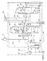
- Fig. 1 ein Schaltbild einer hydraulischen Steuervorrichtung,
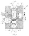
- Fig. 2 ein Wegeventil der Steuervorrichtung von Fig. 1 in einem Längsschnitt, und
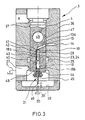
- Fig. 3 das Wegeventil von Fig. 2 in einer um 90° gegenüber Fig.2 gedrehten Schnittansicht.
- 1 is a circuit diagram of a hydraulic control device,
- Fig. 2 shows a directional control valve of the control device of Fig. 1 in a longitudinal section, and
- 3 shows the directional control valve from FIG. 2 in a sectional view rotated by 90 ° with respect to FIG.
Eine hydraulische Steuervorrichtung 1 gemäß Fig. 1, die beispielsweise für einen Hub- oder Gabelstapler mit mehreren hydraulischen Verbrauchern wie einem einseitig beaufschlagbaren Hubzylinder 2 und einem doppelseitig beaufschlagbaren Neigungszylinder 2a bestimmt ist, enthält der Anzahl der Verbraucher entsprechend viele Wegeventile, im vorliegenden Fall zwei Wegeventile 3 und 3a. Die beiden Wegeventile 3 und 3a sind zueinander parallel an eine Pumpenleitung 6 angeschlossen, die aus einer Druckquelle P, z.B. einer Konstantpumpe, versorgt wird. Die Wegeventile 3, 3a sind an eine gemeinsame Rücklaufleitung 7 zu einem Tank R angeschlossen. Zwischen der Pumpenleitung 6 und der Rücklaufleitung 7 ist eine Druckwaage 8 üblicher Bauart vorgesehen, die einen Schieber 10 enthält, der zwischen einer Absperrstellung (Fig. 1) und einer Durchgangsstellung stufenlos verstellbar ist und eine direkte, mehr oder weniger gedrosselte Verbindung zur Rücklaufleitung 7 herstellen kann. Der Schieber 10 wird von einer Feder 9 in Richtung auf seine Sperrstellung zu belastet.A hydraulic control device 1 according to FIG. 1, the For example, for a forklift or forklift truck with several hydraulic consumers, such as a
Aus der Pumpenleitung 6 wird ein angeschlossener Steuerleitungskreis S mit Druckmittel versorgt. Eine erste Steuerleitung 12 zweigt von der Pumpenleitung 6 ab und führt über beide Wegeventile 3, 3a zu einem Entlastungsanschluß 11 der Rücklaufleitung 7. In jedem Wegeventil 3, 3a ist ein Steuerglied 4, 4a verstellbar, das einen Strömungskanal 29 aufweist, der in der Neutralstellung 0 (Fig. 1) den Durchgang von der ersten Steuerleitung 12 zum Entlastungsanschluß 11 herstellt. Eine zweite Steuerleitung 14 führt von der Federseite der Druckwaage 8 zunächst zu einer Verbindungsstelle 12a mit der ersten Steuerleitung 12 und weiter zu einem Lastdruck-Anzapf-Anschluß 13 des Wegeventils 3. An die zweite Steuerleitung 14 ist ein Steuerleitungszweig 14a zum Lastdruck-Anzapf- Anschluß des Wegeventils 3a geführt. Ferner führt ein Steuerleitungszweig 14b über ein Druckbegrenzungsventil 20 für den Systemdruck vom Steuerleitungszweig 14a zur Rücklaufleitung 7. Eine dritte Steuerleitung 15 führt von der Pumpenleitung 6 zur anderen Seite des Schiebers 10 der Druckwaage 8.A connected control line circuit S is supplied with pressure medium from the pump line 6. A
In der ersten Steuerleitung 12 ist stromauf der Verbindungsstelle 12a eine erste Drosselstelle 16 vorgesehen. Deren Eingangsdruck wird über die dritte Steuerleitung 15 an die der Federseite gegenüberliegende Seite des Schiebers 10 in der Druckwaage 8 übertragen. Eine zweite Drosselstelle 17 für die zweite Steuerleitung 14 ist , z.B. im Steuerglied 4, im Wegeventil 3 vorgesehen. Deren Eingangsdruck wird in der zweite Steuerleitung 14 an die Federseite des Schiebers 10 der Druckwaage 8 übertragen. Der Durchflußwiderstand der ersten Drosselstelle 16 ist kleiner als der Durchflußwiderstand der zweiten Drosselstelle 17.A
In beiden Wegeventilen 3, 3a ist das Steuerglied 4, 4a aus der Neutralstellung 0 in zwei Steuerstellungen a und b stufenlos verstellbar, wobei in Fig. 1 beim Wegeventil 3 eine Zwischenstellung 0/a des Steuergliedes 4 zwischen der Neutralstellung 0 und der Steuerstellungsendlage a strichliert angedeutet ist, in der das Steuerglied 4 noch weniger als beispielsweise 80% des Hubes in Richtung auf die Steuerstellungsendlage a ausgeführt hat.In both
Das Wegeventil 3 besitzt einen Anschluß 25, an den eine Verbraucherleitung 5 zum Hubzylinder 2 angeschlossen ist, von der ein strichliert angedeuteter Strömungsweg 23 abzweigt, in dem der Druck der Verbraucherleitung 5 ansteht. Zwischen dem Lastdruck-Anzapf-Anschluß 13 und dem Strömungsweg 23 ist im Steuerglied 4 eine Strömungsverbindung herstellbar, sobald das Steuerglied 4 in Richtung auf die Steuerstellung a verstellt wird. Dazu ist im Steuerglied 4 ein Kanal 13a über die zweite Drosselstelle 17 mit einem Kanal 28 verbunden, wobei der Kanal 13a mit dem Lastdruckanzapfanschluß 13 und der Kanal 28 über eine Strömungsverbindung 24 bzw. den Strömungsweg 23 mit der Verbraucherleitung 5 verbindbar ist. Die zweite Drosselstelle 17 ist ein eine Feder 18 aufweisendes Rückschlagventil 19, wobei zur Vorspannung der Feder 18 eine mechanische Verstellvorrichtung 21 (s. Fig. 2, 3) vorgesehen ist.The
Im Steuerglied 4 ist ein Hauptströmungsweg 22 ausgebildet, der in der Steuerstellung a einen Anschluß 26 der Pumpenleitung 6 mit dem Anschluß 25 der Verbraucherleitung 5 verbindet. In der Steuerstellung b verbindet ein Hauptströmungsweg 56 den Anschluß 25 mit einem Anschluß 27 der Rücklaufleitung 7. Absperrbare Anschlüsse 30, 31 dienen beim Hub in die Steuerstellung a zum Absprerren des Strömungsweges für die Steuerleitung 12.A
Das zweite Wegeventil 3a für den Neigezylinder 2a ist mit diesem über Verbraucherleitungen 5a und 5b verbunden. Sein Steuerglied 4a enthält Hauptströmungswege 32, 33 und 34, 35 um die wechselweise Beaufschlagung beider Seiten des Neigezylinders steuern zu können. Eine weitere zweite Drosselstelle 17a ist im Steuerleitungszweig 14a enthalten. Ihr Eingangsdruck steht an der Federseite des Schiebers 10 der Druckwaage 8 dann an, wenn das zweite Wegeventil 2a betätigt wird. Gegebenenfalls ist bei der Drosselstelle 17a ein Rückschlagventil vorgesehen.The second directional valve 3a for the tilt cylinder 2a is connected to it via
Die Steuerglieder 4, 4a der Wegeventile 3, 3a sind mit Betätigungselementen 38 verstellbar. Denkbar ist es auch, die Steuerglieder durch Druckbeaufschlagung an den Enden zu verstellen.The
Das Wegeventil 3 (Fig. 2, 3) besitzt in einem quaderförmigen Gehäuse 36 eine längsdurchgehende Bohrung 37 für das als Schieberkolben ausgebildete Steuerglied 4. Die Betätigung 38 (Pfeil) greift am oberen Ende des Steuergliedes 4 an. Am unteren Ende ist die Bohrung 37 durch eine Endwand 39 verschlossen, die mit der Verstellvorrichtung 21 für die Feder 18 des Rückschlagventils 19 zusammenarbeitet.The directional control valve 3 (FIGS. 2, 3) has, in a
Das Rückschlagventil 19 ist im Inneren des Steuergliedes 4 angeordnet, und zwar in einer Kammer 40, in der am oberen Ende eine Sitz 41 für ein kugelförmiges Schließglied 42 des Rückschlagventils 19 vorgesehen ist. Dem Schließglied 42 liegt unten ein Federteller 43 am oberen Ende 18a der Feder 18 gegenüber. Das untere Ende 18b der Feder 18 sitzt auf einem Federteller 48, der auf einem in die Kammer 40 von unten eingeschraubten Einsatz 44 abhebbar abgestützt ist. Zwischen den Federtellern 48 und 43 ist die Feder 18 wenn überhaupt, mit einer sehr kleinen Vorspannung gehalten. Gegebenenfalls kann das Schließglied 42 sogar einen geringen Leerhub ausführen. Im Federteller 48 ist ein Koppelglied 45, z.B. ein längsverschiebbarer Stößel, gehalten, das mit seinem freien Ende 46 zur Endwand 39 ragt. Zwischen dem freien Ende 46 und der Endwand 39, die ein Widerlager für das freie Ende 46 bildet, liegt in der Neutralstellung des Steuergliedes 4 ein Abstand x vor. Der Durchmesser des Stößels liegt bei etwa 1mm.The
Der in Fig. 1 angedeutete Kanal 13a beginnt am Außenumfang des Steuergliedes 4 in einer längsverlaufenden Strömungstasche 47 und führt zur dem Schließglied 42 abgewandten Seite des Sitzes 41. Der Kanal 28 führt von der Kammer 40 zum Außenumfang des Steuergliedes 4. Im Gehäuse 36 ist die zweite Steuerleitung 14 erkennbar, die zum Lastdruck-Anzapf-Anschluß 13 in der Wand der Bohrung 37 führt. Eine Eindrehung in der Bohrung 37 stellt den Anschluß 25 zur Verbraucherleitung 5 dar und bildet beim Hub zur Steuerstellung a den in Fig. 1 angedeuteten Strömungsweg bzw. Strömungskanal 23, 24. In der dargestellten Neutralstellung des Steuergliedes 4 ist der Lastdruck-Anzapf-Anschluß 13 mit dem Kanal 13a verbunden. Hingegen deckt die Bohrungswand die Mündung des Kanals 28 ab, der somit vom Anschluß 25 getrennt ist. Gemäß Fig. 2 ist das Steuerglied 4 mit zwei diametral gegenüberliegenden, längsverlaufenden, großen Strömungstaschen ausgestattet, die in der Steuerstellung a den in Fig. 1 angedeuteten Hauptströmungsweg 22 bilden und durch (Fig. 3) eine Bohrung 49 verbunden sind. Die Strömungstaschen stehen vor dem Anschluß 26 zur Druckquelle P. Der Umfang des Steuergliedes 4 trennt den Anschluß 25 vom Anschluß 26.The indicated in Fig. 1
Bei Verstellung des Steuergliedes 4 nach unten (Steuerstellung a) arbeiten die Strömungstaschen (Strömungsweg 22) blendenartig mit dem Anschluß 25 zusammen, um eine mehr oder weniger gedrosselte Verbindung von der Pumpenleitung 6 zur Verbraucherleitung 5 herzustellen.When the
Wird das Steuerglied 4 aus der Neutralstellung nach oben verschoben, so trennt der Außenumfang des Steuergliedes 4 den Anschluß 25 vom Anschluß 26, während das untere Ende (Strömungsweg 56) des Steuergliedes 4 den Anschluß 25 zum Anschluß 27 im unteren Ende der Bohrung 37 freigibt, so daß das Druckmittel aus dem Hubzylinder 2 abströmt.If the
Der Lastdruck-Anzapf-Anschluß 13 liegt in dem Umfangsbereich der Bohrungswand, dem entlang bei der Verstellung des Steuergliedes 4 die zwischen den großen Strömungstaschen liegende, davon getrennte Strömungstasche 47 verfahren wird. Das Steuerglied 4 ist gegen Verdrehung gesichert. Zwischen der Neutralstellung und der Steuerstellung a ist die Verbindung zwischen der zweiten Steuerleitung 14 und dem Kanal 13a offen. Die Mündung des Kanals 28 am Umfangs des Steuergliedes 4 liegt in der Neutralstellung (Fig. 3) in einem Abstand oberhalb der den Anschluß 25 bildenden Eindrehung, der annähernd dem Abstand x entspricht. An den untenliegenden Enden (Fig. 2) der großen Strömungstaschen sind schräge Flächen 57 gebildet, die - Umfangsrichtung versetzt - in etwa auf der gleichen axialen Höhe in den Umfang des Steuergliedes 4 einlaufen wie die Mündung des Kanals 28. Sobald die Flächen 57 in die den Anschluß 25 bildende Eindrehung einzutreten beginnen, entstehen blendenartig Öffnungen, durch die das Druckmittel vom Anschluß 26 zur Verbraucherleitung strömt. Im gleichen Moment oder sogar mit einer geringfügigen Voreilung tritt auch die Mündung des Kanals 28 in die Eindrehung ein. Der im Anschluß 25 herrschende Druck wird auf diese Weise stets in die Kammer 40 übertragen, wo er das Schließglied 42 gegen den Sitz 41 drückt.The load
Gemäß den Fig. 1 bis 3 wird zuvor der Strömungskanal 29 im Steuerglied 4 abgesperrt, so daß die erste Steuerleitung 12 nicht mehr mit dem Entlastungsanschluß 11 verbunden ist. Unter der Annahme, daß das zweite Wegeventil 3a nicht betätigt ist, wird der Schieber 10 der Druckwaage 8 verstellt, bis er allmählich abdrosselt. Mit steigendem Druck in der Pumpenleitung 6 steigt auch der Druck im Steuerleitungskreis S. Der Druck in der zweiten Steuerleitung 14 steht über den Kanal 13a am Schließglied 42 an. Druckmittel strömt am Schließglied 42 vorbei zur Verbraucherleitung 5 , so daß sich der Druck in der zweiten Steuerleitung 14 auf einen Wert einstellt, der annähernd dem Verbraucherdruck gleich ist. Sobald beim weiteren Verschieben des Steuergliedes 4 in Richtung auf die Steuerstellungsendlage das freie Ende 46 des Koppelgliedes 45 an der die Endwand 39 zur Anlage kommt, wird der Federteller 48 vom Einsatz 44 abgehoben. Die Feder 18 wird entsprechend der Hubbewegung des Steuergliedes 4 vorgespannt. Dadurch entsteht eine Schließkraft im Rückschlagventil 19 und der Durchflußwiderstand für das Druckmittel in der zweiten Steuerleitung 14 steigt an. Es steigt der Druck in der zweiten Steuerleitung 14 an, was dazu führt, daß die Druckwaage 8 stärker abdrosselt, wodurch der Druck in der Pumpenleitung 6 weiter ansteigt. Bis zum Erreichen der Steuerstellungsendlage wird auf diese Weise der Druck in der zweiten Steuerleitung und davon abhängig in der Pumpenleitung 6 erhöht, und zwar nicht nur in Abhängigkeit vom ansteigenden Lastdruck in der Verbraucherleitung 5, sondern zusätzlich durch die progressive Vorspannung der Feder 18. Zweckmäßigerweise ist die Erhöhung der Vorspannung der Feder 18 hauptsächlich im sogenannten Feinsteuerbereich des Steuergliedes 4 wirksam, d.h. zwischen der Hubstellung, in der die Flächen 57 gerade in die den Anschluß 25 bildende Eindrehung einzutreten beginnen, z.B. ab 50l/min, und der Hubstellung, in der die großen Strömungstaschen des Strömungsweges 22 im wesentlichen ungedrosselt zum Anschluß 25 frei sind. Entsprechend wächst die Druckdifferenz zwischen dem Druck in der Pumpenleitung 6 und dem Druck in der Verbraucherleitung 5 stetig an. Beim Zurückbewegen des Steuergliedes 4 in die Neutralstellung nimmt die Vorspannung der Feder 18 wieder entsprechend dem Hubweg ab.According to FIGS. 1 to 3, the flow channel 29 in the
Wird das Steuerglied 4 in der Gegenrichtung verschoben, so verbindet der Strömungsweg 56 den Anschluß 25 mit dem Anschluß 27, so daß das Druckmittel abströmen kann. Das Rückschlagventil 19 ist dann ohne Funktion und geschlossen.If the
Wird das zweite Wegeventil 3a aus seiner Neutralstellung verstellt, so erfolgt die Druckanhebung in der Pumpenleitung 6 durch die Wirkung der zweiten Drosselstelle 17a für den gesamten Arbeitsbereich des Wegeventils 3a mit gleichbleibendem Unterschied zum Druck in einer der Verbraucherleitungen 5a oder 5b. Werden beiden Wegeventile 3, 3a gleichzeitig betätigt, so erfolgt die Druckanhebung in Abhängigkeit vom jeweils niedrigeren Eingangsdruck einer der zweiten Drosselstellen 17 bzw. 17a. Soll dies vermieden werden, so sind nicht dargestellte Mittel vorgesehen, die dem Wegeventil 3 Vorrang gegenüber dem Wegeventil 3a einräumen.If the second directional valve 3a is adjusted from its neutral position, the pressure in the pump line 6 is raised by the action of the second throttle point 17a for the entire working range of the directional valve 3a with a constant difference to the pressure in one of the
Das Rückschlagventil 19, dessen Federvorspannung in Abhängigkeit vom Hub des Steuergliedes 4 veränderbar ist, kann auch außerhalb des Wegeventils oder im Gehäuse des Wegeventils in der zweiten Steuerleitung 14 angeordnet sein. Ferner ist es ohne weiteres möglich, jedes der Wegeventile der Steuervorrichtung 1 für jede Beaufschlagungsrichtung mit einem solchen Rückschlagventil mit vorspannbarer Feder auszustatten, so daß die exakt bedarfsangepaßte Druckanhebung für jeden Verbraucher und sogar für jede Arbeitsrichtung, gegebenenfalls dann in unterschiedlichem Maß, wirksam ist. Im Steuerkreis können ferner Wechselventile vorgesehen werden, die dafür sorgen, daß jeweils der Verbraucher bzw. die Verbraucherarbeitsrichtung Vorrang gegenüber den anderen erhält, die gerade die größte Druckmittelmenge benötigt.The
Anstelle der mechanischen Verstellvorrichtung 21 für die Feder 18 könnte auch eine hydraulische oder elektrische Verstellvorrichtung vorgesehen werden. Bei einer hydraulischen Verstellvorrichtung kann beispielsweise der Verbraucherdruck im Anschluß 25 auf einen Kolben gebracht werden, an dem sich die Feder 18 abstützt und der mit steigendem Verbraucherdruck die Feder 18 vorspannt. Auch hierbei wäre die Vorspannung strikt abhängig vom Hub des Steuergliedes, weil mit zunehmendem Hub des Steuergliedes in Richtung auf die Steuerstellungsendlage der Druck im Anschluß 25 entsprechend zunimmt.Instead of the
In Fig. 3 ist strichliert eine Verstellschraube 50 in der Endwand 39 angedeutet, deren Ende das Widerlager 39′ für das freie Ende 45 bildet. Durch Verstellen der Schraube 50 läßt sich der Abstand x und damit der Punkt verändern, ab dem die Feder 18 vorgespannt wird.In Fig. 3 a dashed
Claims (8)
Priority Applications (1)
| Application Number | Priority Date | Filing Date | Title |
|---|---|---|---|
| AT89102903T ATE101900T1 (en) | 1988-03-08 | 1989-02-20 | HYDRAULIC CONTROL DEVICE. |
Applications Claiming Priority (2)
| Application Number | Priority Date | Filing Date | Title |
|---|---|---|---|
| DE3807583A DE3807583C1 (en) | 1988-03-08 | 1988-03-08 | |
| DE3807583 | 1988-03-08 |
Publications (3)
| Publication Number | Publication Date |
|---|---|
| EP0331958A2 true EP0331958A2 (en) | 1989-09-13 |
| EP0331958A3 EP0331958A3 (en) | 1991-04-10 |
| EP0331958B1 EP0331958B1 (en) | 1994-02-23 |
Family
ID=6349164
Family Applications (1)
| Application Number | Title | Priority Date | Filing Date |
|---|---|---|---|
| EP89102903A Expired - Lifetime EP0331958B1 (en) | 1988-03-08 | 1989-02-20 | Hydraulic control device |
Country Status (5)
| Country | Link |
|---|---|
| US (1) | US4941321A (en) |
| EP (1) | EP0331958B1 (en) |
| JP (1) | JPH07109206B2 (en) |
| AT (1) | ATE101900T1 (en) |
| DE (2) | DE3807583C1 (en) |
Cited By (2)
| Publication number | Priority date | Publication date | Assignee | Title |
|---|---|---|---|---|
| WO1998005870A1 (en) * | 1996-08-07 | 1998-02-12 | Mannesmann Rexroth Ag | Hydraulic control device |
| WO1998044266A1 (en) * | 1997-04-02 | 1998-10-08 | Voith Turbo Gmbh & Co. Kg | Valve device, especially a combined proportional-distributing valve device |
Families Citing this family (5)
| Publication number | Priority date | Publication date | Assignee | Title |
|---|---|---|---|---|
| US5081839A (en) * | 1990-01-29 | 1992-01-21 | Caterpillar Inc. | Pressure compensated hydraulic system |
| DE19960302A1 (en) * | 1999-12-14 | 2001-06-21 | Meiller Fahrzeuge | Control valve device for hydraulic cylinder, which in blocking bypass state can act as pressure limiting valve acting towards container |
| DE10224741A1 (en) * | 2002-06-04 | 2003-12-18 | Linde Ag | Hydraulic lifting device |
| GB2501486A (en) * | 2012-04-24 | 2013-10-30 | Jc Bamford Excavators Ltd | Work machine having a hydraulic system comprising variable orifice ratios |
| JP5978900B2 (en) * | 2012-06-07 | 2016-08-24 | 株式会社ジェイテクト | solenoid valve |
Citations (4)
| Publication number | Priority date | Publication date | Assignee | Title |
|---|---|---|---|---|
| US3971216A (en) * | 1974-06-19 | 1976-07-27 | The Scott & Fetzer Company | Load responsive system with synthetic signal |
| DE2620041A1 (en) * | 1976-05-06 | 1977-11-24 | Bosch Gmbh Robert | Hydraulic controller with load control valve - has valve control element which cuts off line passing to load and has two positions |
| DE3611244A1 (en) * | 1986-04-04 | 1987-10-08 | Rexroth Mannesmann Gmbh | Flow-control valve |
| DE3722083C1 (en) * | 1987-07-03 | 1988-09-15 | Heilmeier & Weinlein | Hydraulic control device |
Family Cites Families (5)
| Publication number | Priority date | Publication date | Assignee | Title |
|---|---|---|---|---|
| US971216A (en) * | 1909-05-29 | 1910-09-27 | William C Robinson | Fitting for electric conduits. |
| DE2804045A1 (en) * | 1978-01-31 | 1979-08-09 | Bosch Gmbh Robert | CONTROL DEVICE FOR A HYDRAULICALLY OPERATED CONSUMER |
| US4436020A (en) * | 1982-03-11 | 1984-03-13 | Caterpillar Tractor Company | Dual input pressure compensated fluid control valve |
| JPS60109604A (en) * | 1983-11-15 | 1985-06-15 | Daikin Ind Ltd | Fluid circuit |
| FR2569786B1 (en) * | 1984-08-31 | 1987-03-20 | Vickers Systems Sa | HIGH PRESSURE HYDRAULIC VALVE WITH STEERING PRESSURE GENERATOR |
-
1988
- 1988-03-08 DE DE3807583A patent/DE3807583C1/de not_active Expired
-
1989
- 1989-02-20 DE DE89102903T patent/DE58907019D1/en not_active Expired - Fee Related
- 1989-02-20 EP EP89102903A patent/EP0331958B1/en not_active Expired - Lifetime
- 1989-02-20 AT AT89102903T patent/ATE101900T1/en not_active IP Right Cessation
- 1989-03-06 US US07/320,076 patent/US4941321A/en not_active Expired - Lifetime
- 1989-03-08 JP JP1055990A patent/JPH07109206B2/en not_active Expired - Lifetime
Patent Citations (4)
| Publication number | Priority date | Publication date | Assignee | Title |
|---|---|---|---|---|
| US3971216A (en) * | 1974-06-19 | 1976-07-27 | The Scott & Fetzer Company | Load responsive system with synthetic signal |
| DE2620041A1 (en) * | 1976-05-06 | 1977-11-24 | Bosch Gmbh Robert | Hydraulic controller with load control valve - has valve control element which cuts off line passing to load and has two positions |
| DE3611244A1 (en) * | 1986-04-04 | 1987-10-08 | Rexroth Mannesmann Gmbh | Flow-control valve |
| DE3722083C1 (en) * | 1987-07-03 | 1988-09-15 | Heilmeier & Weinlein | Hydraulic control device |
Non-Patent Citations (1)
| Title |
|---|
| US-A3 971 216 * |
Cited By (2)
| Publication number | Priority date | Publication date | Assignee | Title |
|---|---|---|---|---|
| WO1998005870A1 (en) * | 1996-08-07 | 1998-02-12 | Mannesmann Rexroth Ag | Hydraulic control device |
| WO1998044266A1 (en) * | 1997-04-02 | 1998-10-08 | Voith Turbo Gmbh & Co. Kg | Valve device, especially a combined proportional-distributing valve device |
Also Published As
| Publication number | Publication date |
|---|---|
| DE3807583C1 (en) | 1989-03-09 |
| EP0331958A3 (en) | 1991-04-10 |
| EP0331958B1 (en) | 1994-02-23 |
| JPH01279102A (en) | 1989-11-09 |
| US4941321A (en) | 1990-07-17 |
| DE58907019D1 (en) | 1994-03-31 |
| ATE101900T1 (en) | 1994-03-15 |
| JPH07109206B2 (en) | 1995-11-22 |
Similar Documents
| Publication | Publication Date | Title |
|---|---|---|
| DE2343611C2 (en) | Device for load-dependent control of a hydrostatic variable displacement pump | |
| DE3345264A1 (en) | TORQUE CONTROL UNIT FOR AN ADJUSTABLE HYDROPUMP | |
| DE3305092C2 (en) | ||
| EP1148251B1 (en) | Pressure control valve | |
| EP0103250B1 (en) | Fluid control control valve | |
| DE4224973A1 (en) | Oil supply pressure control - uses multistage valve with oil filter acting as resistance and throttle | |
| EP0331958B1 (en) | Hydraulic control device | |
| DE3320047C2 (en) | ||
| DE2336512C2 (en) | Valve | |
| DE1169746B (en) | Spring-loaded pressure relief valve with a spring-loaded auxiliary valve causing it to be triggered | |
| DE3919175C2 (en) | ||
| DE2513548C3 (en) | Device for controlling the delivery rate of adjustable axial piston pumps | |
| DE10015971A1 (en) | Oil pump for vehicle engine has pilot pressure non-return valve in inner chamber that releases pilot pressure to balance pilot pressure and output pressure | |
| DE1577181C3 (en) | Control system for maintaining the angle) - or ParsUeiiage of the ram or press beam of a hydraulic press or scissors | |
| DE10007291A1 (en) | Pressure reducing valve | |
| EP0483585B1 (en) | Adjustable proportional throttle valve with feedback | |
| DE2506923B2 (en) | VALVE DEVICE | |
| DE2813791A1 (en) | REGULATING DEVICE FOR PUMPS WITH VARIABLE OUTPUT | |
| DE2537957A1 (en) | TAX OR CONTROL ARRANGEMENT FOR PUMPS WITH VARIABLE DISPLACEMENT | |
| DE2656377A1 (en) | PUMP ARRANGEMENT | |
| EP0375916B1 (en) | Directional valve for controlling a hydraulic cylinder | |
| DE3739824C2 (en) | Pilot operated 3-way pressure control valve | |
| DE2205508C2 (en) | Hydraulic control device | |
| DE3039002A1 (en) | Operating pressure control valve - has control piston with throttle plunger whose position controls switch for load pressure indication | |
| DE1798427C3 (en) | Hydraulic control valve in slide design |
Legal Events
| Date | Code | Title | Description |
|---|---|---|---|
| PUAI | Public reference made under article 153(3) epc to a published international application that has entered the european phase |
Free format text: ORIGINAL CODE: 0009012 |
|
| AK | Designated contracting states |
Kind code of ref document: A2 Designated state(s): AT BE CH DE ES FR GB GR IT LI LU NL SE |
|
| PUAL | Search report despatched |
Free format text: ORIGINAL CODE: 0009013 |
|
| AK | Designated contracting states |
Kind code of ref document: A3 Designated state(s): AT BE CH DE ES FR GB GR IT LI LU NL SE |
|
| 17P | Request for examination filed |
Effective date: 19910411 |
|
| RAP3 | Party data changed (applicant data changed or rights of an application transferred) |
Owner name: HEILMEIER & WEINLEIN FABRIK FUER OEL-HYDRAULIK GMB |
|
| 17Q | First examination report despatched |
Effective date: 19930429 |
|
| GRAA | (expected) grant |
Free format text: ORIGINAL CODE: 0009210 |
|
| AK | Designated contracting states |
Kind code of ref document: B1 Designated state(s): AT BE CH DE ES FR GB GR IT LI LU NL SE |
|
| PG25 | Lapsed in a contracting state [announced via postgrant information from national office to epo] |
Ref country code: IT Free format text: LAPSE BECAUSE OF FAILURE TO SUBMIT A TRANSLATION OF THE DESCRIPTION OR TO PAY THE FEE WITHIN THE PRE;WARNING: LAPSES OF ITALIAN PATENTS WITH EFFECTIVE DATE BEFORE 2007 MAY HAVE OCCURRED AT ANY TIME BEFORE 2007. THE CORRECT EFFECTIVE DATE MAY BE DIFFERENT FROM THE ONE RECORDED.SCRIBED TIME-LIMIT Effective date: 19940223 Ref country code: NL Effective date: 19940223 Ref country code: FR Free format text: THE PATENT HAS BEEN ANNULLED BY A DECISION OF A NATIONAL AUTHORITY Effective date: 19940223 Ref country code: SE Effective date: 19940223 Ref country code: GR Free format text: LAPSE BECAUSE OF FAILURE TO SUBMIT A TRANSLATION OF THE DESCRIPTION OR TO PAY THE FEE WITHIN THE PRESCRIBED TIME-LIMIT Effective date: 19940223 Ref country code: BE Effective date: 19940223 Ref country code: GB Effective date: 19940223 Ref country code: ES Free format text: THE PATENT HAS BEEN ANNULLED BY A DECISION OF A NATIONAL AUTHORITY Effective date: 19940223 |
|
| REF | Corresponds to: |
Ref document number: 101900 Country of ref document: AT Date of ref document: 19940315 Kind code of ref document: T |
|
| REF | Corresponds to: |
Ref document number: 58907019 Country of ref document: DE Date of ref document: 19940331 |
|
| EN | Fr: translation not filed | ||
| NLV1 | Nl: lapsed or annulled due to failure to fulfill the requirements of art. 29p and 29m of the patents act | ||
| GBV | Gb: ep patent (uk) treated as always having been void in accordance with gb section 77(7)/1977 [no translation filed] |
Effective date: 19940223 |
|
| PLBE | No opposition filed within time limit |
Free format text: ORIGINAL CODE: 0009261 |
|
| STAA | Information on the status of an ep patent application or granted ep patent |
Free format text: STATUS: NO OPPOSITION FILED WITHIN TIME LIMIT |
|
| 26N | No opposition filed | ||
| PG25 | Lapsed in a contracting state [announced via postgrant information from national office to epo] |
Ref country code: AT Effective date: 19950220 |
|
| PG25 | Lapsed in a contracting state [announced via postgrant information from national office to epo] |
Ref country code: LI Effective date: 19950228 Ref country code: CH Effective date: 19950228 Ref country code: LU Free format text: LAPSE BECAUSE OF NON-PAYMENT OF DUE FEES Effective date: 19950228 |
|
| PGFP | Annual fee paid to national office [announced via postgrant information from national office to epo] |
Ref country code: DE Payment date: 20060330 Year of fee payment: 18 |
|
| PG25 | Lapsed in a contracting state [announced via postgrant information from national office to epo] |
Ref country code: DE Free format text: LAPSE BECAUSE OF NON-PAYMENT OF DUE FEES Effective date: 20070901 |