EP0331670A1 - Verfahren und Einrichtung zur Bestimmung innenballistischer Kenngrössen in Rohrwaffen - Google Patents
Verfahren und Einrichtung zur Bestimmung innenballistischer Kenngrössen in Rohrwaffen Download PDFInfo
- Publication number
- EP0331670A1 EP0331670A1 EP89890058A EP89890058A EP0331670A1 EP 0331670 A1 EP0331670 A1 EP 0331670A1 EP 89890058 A EP89890058 A EP 89890058A EP 89890058 A EP89890058 A EP 89890058A EP 0331670 A1 EP0331670 A1 EP 0331670A1
- Authority
- EP
- European Patent Office
- Prior art keywords
- coupling
- projectile
- weapon barrel
- barrel
- wave
- Prior art date
- Legal status (The legal status is an assumption and is not a legal conclusion. Google has not performed a legal analysis and makes no representation as to the accuracy of the status listed.)
- Withdrawn
Links
- 238000000034 method Methods 0.000 title claims description 15
- 230000007704 transition Effects 0.000 claims abstract description 38
- 238000005259 measurement Methods 0.000 claims abstract description 11
- 230000001066 destructive effect Effects 0.000 claims abstract description 6
- 230000008878 coupling Effects 0.000 claims description 81
- 238000010168 coupling process Methods 0.000 claims description 81
- 238000005859 coupling reaction Methods 0.000 claims description 81
- 238000011156 evaluation Methods 0.000 claims description 7
- 230000010363 phase shift Effects 0.000 claims description 5
- 230000007480 spreading Effects 0.000 claims description 4
- 230000003068 static effect Effects 0.000 claims description 4
- 238000006073 displacement reaction Methods 0.000 claims description 3
- 230000001902 propagating effect Effects 0.000 claims description 2
- 230000008859 change Effects 0.000 abstract description 3
- 238000000605 extraction Methods 0.000 abstract 1
- 238000010304 firing Methods 0.000 abstract 1
- 238000002347 injection Methods 0.000 abstract 1
- 239000007924 injection Substances 0.000 abstract 1
- 238000013461 design Methods 0.000 description 5
- 230000001133 acceleration Effects 0.000 description 3
- 230000000694 effects Effects 0.000 description 3
- 239000007789 gas Substances 0.000 description 3
- 238000004519 manufacturing process Methods 0.000 description 3
- 239000000843 powder Substances 0.000 description 3
- 230000006399 behavior Effects 0.000 description 2
- 238000006243 chemical reaction Methods 0.000 description 2
- 210000000078 claw Anatomy 0.000 description 2
- 230000001052 transient effect Effects 0.000 description 2
- 230000006978 adaptation Effects 0.000 description 1
- 230000003321 amplification Effects 0.000 description 1
- QVGXLLKOCUKJST-UHFFFAOYSA-N atomic oxygen Chemical compound [O] QVGXLLKOCUKJST-UHFFFAOYSA-N 0.000 description 1
- 230000015572 biosynthetic process Effects 0.000 description 1
- 230000000903 blocking effect Effects 0.000 description 1
- 238000011161 development Methods 0.000 description 1
- 239000003574 free electron Substances 0.000 description 1
- 230000006870 function Effects 0.000 description 1
- 230000009931 harmful effect Effects 0.000 description 1
- 238000010327 methods by industry Methods 0.000 description 1
- 239000000203 mixture Substances 0.000 description 1
- 239000012811 non-conductive material Substances 0.000 description 1
- 238000003199 nucleic acid amplification method Methods 0.000 description 1
- 239000001301 oxygen Substances 0.000 description 1
- 229910052760 oxygen Inorganic materials 0.000 description 1
- 230000035515 penetration Effects 0.000 description 1
- 238000012545 processing Methods 0.000 description 1
- 230000009467 reduction Effects 0.000 description 1
Images

Classifications
-
- G—PHYSICS
- G01—MEASURING; TESTING
- G01P—MEASURING LINEAR OR ANGULAR SPEED, ACCELERATION, DECELERATION, OR SHOCK; INDICATING PRESENCE, ABSENCE, OR DIRECTION, OF MOVEMENT
- G01P3/00—Measuring linear or angular speed; Measuring differences of linear or angular speeds
- G01P3/64—Devices characterised by the determination of the time taken to traverse a fixed distance
- G01P3/66—Devices characterised by the determination of the time taken to traverse a fixed distance using electric or magnetic means
- G01P3/665—Devices characterised by the determination of the time taken to traverse a fixed distance using electric or magnetic means for projectile velocity measurements
Definitions
- the invention relates to a method for the non-destructive determination of internal ballistic parameters in tubular weapons, an electromagnetic wave being coupled into the weapon barrel via a waveguide transition arranged on the side of the barrel and being decoupled again after reflection on a projectile located therein, and which changes when the Projectile position in the weapon barrel changing phase position between the coupled and decoupled shaft is used as a measurement signal.
- the invention also relates to a device for carrying out such a method on a weapon barrel with a projectile located therein, with a unit for generating the shaft to be coupled in, a connection therewith and one arranged laterally in the inner surface of an area swept by the projectile on the weapon barrel Coupling device having a waveguide transition for coupling and decoupling the shafts and an evaluation unit which is also connected to the coupling device.
- Such methods and devices are known (see, for example, US Pat. No. 4,283,989) and are used essentially to determine the speed or acceleration conditions on a projectile still in the weapon barrel, which allow statements about the internal ballistic conditions and either during the further development of the Weapon or ammunition can be used or can also be used, for example, to correct a time fuse on the floor to take into account the actual muzzle velocity. It is usually carried out in the microwave range (wavelengths in the millimeter or centimeter range), the wavelength used in each case depending, among other things, on the tube caliber.
- the weapon barrel is used as a waveguide for the microwaves coupled in via the lateral transition, in which different modes or wave types develop, essentially depending on the frequency and barrel caliber the.
- the frequency of the microwaves and the type of coupling are usually chosen so that only a certain type of wave can form.
- the projectile located in the weapon barrel acts as a short-circuit slide, on which the coupled-in wave is reflected, a standing wave being created in the weapon barrel serving as a waveguide by superimposing the coupled-in wave with the reflected wave.
- This standing wave is pushed as it were by the projectile, or the phase position between the coupled-in and the reflected wave is changed.
- This phase shift which is caused by the movement of the projectile and is directly influenced by it, can be detected and evaluated by a suitable measuring arrangement in the form of the so-called Doppler frequency.
- the device expenditure or the microwave hardware essentially corresponds to a low-power Doppler radar, although there are various special requirements, in particular with regard to the coupling in and out of the weapon barrel.
- the useful signal in all known versions usually breaks down or is mostly in the case of a sharp shot superimposed by disturbances which are in the same order of magnitude as the useful signal.
- the object of the present invention is to improve a method or a device of the type mentioned at the outset in such a way that the disadvantages of the known methods or devices are avoided and that especially and especially in the case of a sharp shot, meaningful and significant measurements are usable according to a sufficiently large size Useful signals are possible.
- the invention is based on the consideration that, in the coupling elements used in the previously known methods or devices of the type mentioned, at least half the energy of the electromagnetic wave is emitted instead of being coupled in the direction of the projectile from the muzzle of the weapon barrel.
- the elements provided for the coupling itself usually have only a very poor standing wave ratio, which means that only a relatively small part of the energy actually gets into the weapon barrel and for reflection at the tip of the projectile.
- the standing wave ratio then changes further and interference signals are formed which can easily reach or exceed the size of the useful signal.
- the present invention achieves the above-mentioned object in a method of the type mentioned in that, for coupling the electromagnetic wave, the latter is divided and fed to the weapon barrel at at least two spaced-apart locations of the waveguide transition, so that it moves in the direction of Add the projecting shaft parts and compensate for the shaft parts spreading in the opposite direction.
- This principle which is very simple in terms of design and process engineering, means that the shaft parts coupled into the weapon barrel have such relative phase positions, owing to the spacing of the actual transition openings, that force a clear propagation of the coupled shaft in a certain direction - namely in the direction of the projectile .
- This means that almost 100% of the microwave energy generated can actually be introduced into the weapon barrel, so that any disturbances of the type mentioned remain negligible even when the shot is sharp compared to the useful signal to be evaluated.
- the present invention is realized in that the coupling device has at least two coupling openings, which are arranged at spaced locations on the inner surface of an area swept by the projectile on the weapon barrel in such a way that the wave parts which propagate in the direction of the projectile add up and compensate for the shaft parts that propagate in the opposite direction.
- a projectile dummy interacting with the displacement measuring device can be moved at least in regions through the weapon barrel and the relationship between the current location of the dummy projectile and the phase difference or Doppler frequency can be determined.
- This very simple possibility of calibration allows a clear and extremely precise (depending on the pipe caliber in the range between about 0.1 and a few millimeters) assignment of the measurement signals to the actual floor path or location, even if there are different parameters, such as the slope of the trains , change the length of the gun barrel.
- the coupling device with the individual openings of the waveguide transition can of course also be provided at any point in the wall of the weapon barrel itself, for which purpose essentially only the corresponding openings have to be made on the weapon barrel.
- this reduces the adaptation of the weapon barrel necessary for the method according to the invention to the provision of measures to enable the coupling element to be securely fastened to the muzzle - for example via screw or claw connections; on the other hand, the provision of the coupling openings at the mouth of the weapon barrel enables the corresponding measurements to be taken over the entire length of the weapon barrel, which can occur in the case of a coupling device located further back because of the chemical reactions of the atmospheric oxygen with the hot powder gases that may occur behind the projectile passing by free electrons and the associated influence on the electromagnetic waves is at least problematic.
- the coupling element preferably has, in the inner area swept by the projectile, a cylindrical passage recess having the coupling openings and having an enlarged diameter compared to the weapon barrel, whereby between the passage recess of the coupling element and the weapon barrel also a preferably interchangeable adapter part having a conical transition between the different diameters is arranged can be.
- the cylindrical design of the inner area of the coupling element which is free for the passage of the projectile provides a very simple possibility for coupling the electromagnetic wave, which can thus propagate in the subsequent likewise cylindrical weapon barrel with very little loss.
- the increase in diameter compared to the barrel caliber serves to enable a flawless passage of the projectile, whereby the conical adapter part ensures a possible loss-free coupling into the weapon barrel even while the formation of undesired wave types or reflections is prevented. If this adapter part is interchangeable, a coupling element can also be adapted to different pipe calibers within certain limits.
- the adapter part of the Invention in the area of the conical transition to the outside open recesses for pressure reduction, with which possible negative effects of the pressure of the powder gases behind the projectile on the waveguide transition are prevented.
- the coupling openings can be essentially rectangular and are connected to a corresponding rectangular waveguide, which in turn is connected, preferably by means of a coaxial cable, to the unit for generating the shaft to be coupled in and to the evaluation unit.
- the coupling openings can be closed off by means of electrically non-conductive closure pieces with low dielectric losses in relation to the area swept by the projectile, which prevents the penetration of dirt, as well as harmful effects of the pressures or hot powder gases, into the waveguide transition.
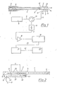
- the device according to FIG. 1 is used to determine internal ballistic parameters in a weapon barrel 1, which, for example, can also be installed in a barrel weapon (not shown here) and, except for the coupling element 2 at the muzzle 3, has no change compared to the standard version.
- a cartridge 5 is inserted with a projectile 6, the movement of which is to be examined through the gun barrel 1 with regard to the path / time relationship or the respective speed and acceleration.
- an electromagnetic wave is coupled into the weapon barrel 1 via at least one waveguide transition 7 arranged in the region of the coupling element 2 and is coupled out again after reflection on the projectile 6, after which the phase position which changes between the coupled and decoupled shaft can be used as a measurement signal for the floor position and after appropriate linkage with the current time for determining speed and acceleration.
- the electromagnetic wave generated in a microwave generator 8 which usually has wavelengths in the millimeter or centimeter range, depending on the caliber of the weapon barrel 1, is fed via a coaxial cable 9 to a circulator 10, from where it functions according to the same via a further coaxial cable 11 a coaxial waveguide transition 12 arrives.
- a coaxial waveguide transition 12 arrives.
- an H-type wave is excited which, via the waveguide transition 7 (this term always means a waveguide-waveguide transition here and below), arrives in the inner region 13 of the coupling element 2 which represents a circular waveguide and is converted, for example, into the cylindrical symmetrical E01 wave.
- the wave reflected from the top of the projectile 6 is coupled out again via the waveguide transition 7 and reaches the coaxial Waveguide transition 12 and the coaxial cable 11 in turn to the circulator 10, where, due to the non-reciprocal behavior of this component, it is decoupled from the wave coming from the microwave generator 8 and fed to a mixer 16. Due to reflections and due to a finite blocking attenuation of the circulator 10, a fraction of the wave coming from the microwave generator 8 is also present on this mixer 16, and therefore there is a mixture between the emitted and the reflected wave.
- the phase difference between these two waves or the Doppler frequency can be tapped, which after appropriate amplification is stored in an amplifier 18 and A / D conversion (not shown here) for the entire time range of a shot in a transient memory 19 becomes.
- a connecting line 20 a computer 21, for example a commercially available PC, is connected to the transient memory 19, which provides further processing and is connected via a line 22 to an output unit 23 ', for example a plotter, for displaying the results.
- FIG. 2 which goes into more detail with regard to the coupling element 2, it can be seen that at the coaxial waveguide transition 12 an antenna pin 42 protrudes into the interior of the waveguide 27, which for example has a rectangular cross section, which in view of the expert in this context common measures enables the generation of an electromagnetic wave in the interior of the waveguide 27 in a simple manner.
- a reflective termination indicated to the left of the transition 12 practically 100% of this wave in the waveguide 27 moves to the right, is divided without factor and enters the inner region 13 of the coupling openings 40, 41 arranged at points 39 spaced in the direction of propagation of the wave Coupling element 2 a.
- a reflection-free termination 43 indicated at the right end of the waveguide 27 in the illustration in FIG. 2 ensures that returning shaft parts in the waveguide 27 which would interfere with the coupling or the described type of addition and compensation are excluded.
- the described way of coupling the electromagnetic wave into the coupling element 2 or via the conical transition 15 into the weapon barrel 1 ensures a high intensity of the wave traveling in the direction of the projectile 6, which in direct consequence also means that the signal reflected at the projectile tip can be very intense leaves.
- the reflected signal is decoupled again in reverse of the principle of coupling described, the advantages of the decoupling divided in the manner described having the effect that the decoupled wave in waveguide 27 runs practically completely to the left, since the direction towards the reflection-free termination 43 Compensate current shares.
- the coupling element 2 shown in FIG. 3 is constructed essentially similarly to that shown only schematically in FIGS. 1 and 2, but here the conical transition 15 is now arranged in an exchangeable adapter part 23, which in the illustration is separate from the others Parts of the coupling element is drawn and can be fastened in a manner which is not of further interest here - for example by screwing or by means of claw couplings - on the one hand on the end face 24 and on the other hand on the weapon barrel (not shown).
- outwardly open slot-shaped recesses 25 are distributed over the circumference, which enable pressure to be reduced and of course have to be designed in such a way that that the incoming or the reflected wave is disturbed as little as possible.
- this coupling opening 40 is essentially rectangular, the narrow sides here being rounded by a end mill due to the manufacture.
- the coupling opening 40 could also have any other suitable cross section - different cross sections or sizes of the individual coupling openings are also possible in order to influence the coupling behavior.
- a bottom for the waveguide 27, which is to be provided as required, is indicated in broken lines in FIG. 3, which then actually turns this waveguide into a rectangular waveguide.
- any other suitable type or cross-sectional shape of the waveguide 27 is conceivable and can be used if necessary in the discretion of the person skilled in the art.
- a closure piece 31 made of electrically non-conductive material with low dielectric losses is arranged according to FIG. 3, which closes the interior of the waveguide 27 against the interior area swept by the projectile and thus the ingress of dirt or any negative effects of remaining Prevents pressure waves.
- the waveguide transition 7' is formed by a plurality of slot-shaped coupling openings 40 'on the circumference of the inner region 13' swept by the projectile.
- the waveguide 27 ' which may in turn have a coaxial waveguide transition, not shown here, for connecting a coaxial cable, is bent in the region of the waveguide transition 7' and runs parallel to the axis of the inner region 13 '.
- the slot-shaped coupling openings 40 'again have a wavelength of the shaft to be coupled in or out, which in turn achieves the advantages already described above.
- a projectile dummy 34 interacting via a push rod 32 with a displacement measuring device 33 is at least partially moved through the weapon barrel 1 for static calibration, which otherwise does not directly pass the waveguide transition 7
- Mattergang here has arranged on the side coupling opening 40, 41 of the weapon barrel 1.
- the signal Via the line 36 corresponding to the coaxial cable 11 in FIG. 1, the signal is supplied to and derived from the waveguide transition 7 ⁇ .
- a path signal corresponding to the respective position of the projectile dummy 34 in the weapon barrel 1 is applied via line 37 to the unit 38, which here comprises both the evaluation unit and the unit for generating the microwaves.
- the projectile dummy 34 can be moved back and forth relatively easily in the weapon barrel 1, an exact association being obtained between the measurement signal obtained as described in FIG. 1 and the actual path of the projectile in the weapon barrel.
- each with a single waveguide transition within the scope of the invention it is of course also possible to arrange a further or even several such transitions - each of which has at least two coupling openings as described - on the weapon barrel, which is simple Optimally couple electromagnetic waves with different frequencies into or out of the weapon barrel so that, for example, different accuracies can be achieved for the different phases of the projectile movement in the weapon barrel.
Landscapes
- Physics & Mathematics (AREA)
- General Physics & Mathematics (AREA)
- Radar Systems Or Details Thereof (AREA)
- Aiming, Guidance, Guns With A Light Source, Armor, Camouflage, And Targets (AREA)
Applications Claiming Priority (2)
| Application Number | Priority Date | Filing Date | Title |
|---|---|---|---|
| AT0057588A AT389764B (de) | 1988-03-04 | 1988-03-04 | Verfahren und einrichtung zur bestimmung innenballistischer kenngroessen in rohrwaffen |
| AT575/88 | 1988-03-04 |
Publications (1)
| Publication Number | Publication Date |
|---|---|
| EP0331670A1 true EP0331670A1 (de) | 1989-09-06 |
Family
ID=3494217
Family Applications (1)
| Application Number | Title | Priority Date | Filing Date |
|---|---|---|---|
| EP89890058A Withdrawn EP0331670A1 (de) | 1988-03-04 | 1989-02-27 | Verfahren und Einrichtung zur Bestimmung innenballistischer Kenngrössen in Rohrwaffen |
Country Status (5)
| Country | Link |
|---|---|
| US (1) | US4928523A (da) |
| EP (1) | EP0331670A1 (da) |
| JP (1) | JPH0217397A (da) |
| AT (1) | AT389764B (da) |
| DK (1) | DK104689A (da) |
Cited By (3)
| Publication number | Priority date | Publication date | Assignee | Title |
|---|---|---|---|---|
| EP1837618A1 (en) * | 2006-03-21 | 2007-09-26 | Honeywell International, Inc. | Mortar blast attenuator diffuser |
| WO2009141055A1 (de) * | 2008-05-21 | 2009-11-26 | Rheinmetall Air Defence Ag | Vorrichtung und verfahren zur messung der mündungsgeschwindigkeit eines projektils oder dergleichen |
| DE102009030862B3 (de) * | 2009-06-26 | 2010-11-25 | Rheinmetall Air Defence Ag | Verfahren und Vorrichtung zur Messung der Mündungsgeschwindigkeit eines Projektils oder dergleichen |
Families Citing this family (18)
| Publication number | Priority date | Publication date | Assignee | Title |
|---|---|---|---|---|
| AT393038B (de) * | 1989-08-28 | 1991-07-25 | Avl Verbrennungskraft Messtech | Verfahren und einrichtung zur bestimmung von bewegungskenngroessen |
| US7100437B2 (en) * | 2003-11-24 | 2006-09-05 | Advanced Design Consulting Usa, Inc. | Device for collecting statistical data for maintenance of small-arms |
| US7082823B1 (en) * | 2005-01-14 | 2006-08-01 | Honeywell International, Inc. | Digital signal processing back biased hall effect muzzle velocity measurement system |
| DE102006058375A1 (de) * | 2006-12-08 | 2008-06-12 | Oerlikon Contraves Ag | Verfahren zur Messung der Mündungsgeschwindigkeit eines Projektils oder dergleichen |
| US8353121B2 (en) | 2007-05-10 | 2013-01-15 | Leitner-Wise Defense, Inc. | Processes and systems for monitoring usage of projectile weapons |
| US8117778B2 (en) | 2007-05-10 | 2012-02-21 | Robert Bernard Iredale Clark | Processes and systems for monitoring environments of projectile weapons |
| DE102007056633B4 (de) * | 2007-11-24 | 2013-01-17 | Krauss-Maffei Wegmann Gmbh & Co. Kg | Rohrwaffe |
| US8800359B2 (en) * | 2009-03-24 | 2014-08-12 | Dynamit Nobel Defense GmbH | Determination of the muzzle velocity of a projectile |
| DE102010006529B4 (de) * | 2010-02-01 | 2013-12-12 | Rheinmetall Air Defence Ag | Verfahren und Vorrichtung zur Übertragung von Energie auf ein Projektil |
| DE102010006530B4 (de) * | 2010-02-01 | 2013-12-19 | Rheinmetall Air Defence Ag | Programmierbare Munition |
| US11933585B2 (en) | 2013-03-27 | 2024-03-19 | Nostromo Holdings, Llc | Method and apparatus for improving the aim of a weapon station, firing a point-detonating or an air-burst projectile |
| US9600900B2 (en) | 2013-03-27 | 2017-03-21 | Nostromo Holdings, Llc | Systems to measure yaw, spin and muzzle velocity of projectiles, improve fire control fidelity, and reduce shot-to-shot dispersion in both conventional and air-bursting programmable projectiles |
| US10514234B2 (en) | 2013-03-27 | 2019-12-24 | Nostromo Holdings, Llc | Method and apparatus for improving the aim of a weapon station, firing a point-detonating or an air-burst projectile |
| US9879963B2 (en) | 2013-03-27 | 2018-01-30 | Nostromo Holdings, Llc | Systems to measure yaw, spin and muzzle velocity of projectiles, improve fire control fidelity, and reduce shot-to-shot dispersion in both conventional and airbursting programmable projectiles |
| DE102015001413B4 (de) * | 2015-02-06 | 2020-02-27 | Rheinmetall Air Defence Ag | Hohlleiteranordnung zur Messung der Geschwindigkeit eines Projektils während des Durchlaufes einer Waffenrohranordnung |
| DE102019134884A1 (de) * | 2019-12-18 | 2021-06-24 | Rheinmetall Air Defence Ag | Detektionsvorrichtung und Verfahren zur Detektion von Störfaktoren in einem Waffenrohr oder Laderohr einer Rohrwaffe |
| US11898831B2 (en) | 2020-04-23 | 2024-02-13 | Ultra Electronics Forensic Technology Inc. | Method and system for creating marks on bullets |
| CN115468451B (zh) * | 2022-08-29 | 2023-08-29 | 山西华洋吉禄科技股份有限公司 | 一种模拟导弹快速离舱的装置 |
Citations (3)
| Publication number | Priority date | Publication date | Assignee | Title |
|---|---|---|---|---|
| FR976704A (fr) * | 1948-10-13 | 1951-03-21 | Comp Generale Electricite | Dispositif de mesure du coefficient de réflexion d'une onde dite h01 ou te01 dans un guide à section circulaire |
| DE2054583A1 (de) * | 1970-11-06 | 1972-05-10 | Licentia Gmbh | Eigenwellenselektiver Richtkoppler |
| EP0023365A2 (en) * | 1979-07-31 | 1981-02-04 | ARES, Inc. | Doppler-type projectile velocity measurement apparatus and method |
Family Cites Families (6)
| Publication number | Priority date | Publication date | Assignee | Title |
|---|---|---|---|---|
| US2735981A (en) * | 1956-02-21 | Microwave interferometer | ||
| US2691761A (en) * | 1948-02-03 | 1954-10-12 | Jr Nicholas M Smith | Microwave measuring of projectile speed |
| US2679631A (en) * | 1950-10-02 | 1954-05-25 | Rca Corp | Power divider |
| US2748350A (en) * | 1951-09-05 | 1956-05-29 | Bell Telephone Labor Inc | Ultra-high frequency selective mode directional coupler |
| BE754626A (fr) * | 1969-08-12 | 1971-01-18 | Oerlikon Buehrle Ag | Installation determinant la vitesse initiale d'un projectile |
| US3918061A (en) * | 1973-09-25 | 1975-11-04 | Terma Elektronisk Industri As | Velocity measuring doppler radar |
-
1988
- 1988-03-04 AT AT0057588A patent/AT389764B/de not_active IP Right Cessation
-
1989
- 1989-02-27 EP EP89890058A patent/EP0331670A1/de not_active Withdrawn
- 1989-03-02 JP JP1048703A patent/JPH0217397A/ja active Pending
- 1989-03-03 US US07/319,098 patent/US4928523A/en not_active Expired - Fee Related
- 1989-03-03 DK DK104689A patent/DK104689A/da not_active Application Discontinuation
Patent Citations (3)
| Publication number | Priority date | Publication date | Assignee | Title |
|---|---|---|---|---|
| FR976704A (fr) * | 1948-10-13 | 1951-03-21 | Comp Generale Electricite | Dispositif de mesure du coefficient de réflexion d'une onde dite h01 ou te01 dans un guide à section circulaire |
| DE2054583A1 (de) * | 1970-11-06 | 1972-05-10 | Licentia Gmbh | Eigenwellenselektiver Richtkoppler |
| EP0023365A2 (en) * | 1979-07-31 | 1981-02-04 | ARES, Inc. | Doppler-type projectile velocity measurement apparatus and method |
Cited By (6)
| Publication number | Priority date | Publication date | Assignee | Title |
|---|---|---|---|---|
| EP1837618A1 (en) * | 2006-03-21 | 2007-09-26 | Honeywell International, Inc. | Mortar blast attenuator diffuser |
| US7798046B2 (en) | 2006-03-21 | 2010-09-21 | Honeywell International Inc. | Mortar blast attenuator diffuser |
| WO2009141055A1 (de) * | 2008-05-21 | 2009-11-26 | Rheinmetall Air Defence Ag | Vorrichtung und verfahren zur messung der mündungsgeschwindigkeit eines projektils oder dergleichen |
| DE102008024574A1 (de) * | 2008-05-21 | 2010-06-17 | Rheinmetall Air Defence Ag | Vorrichtung und Verfahren zur Messung der Mündungsgeschwindigkeit eines Projektils oder dergleichen |
| TWI399514B (zh) * | 2008-05-21 | 2013-06-21 | Rheinmetall Air Defence Ag | 用於測量拋射體或類似物之初速之裝置及方法 |
| DE102009030862B3 (de) * | 2009-06-26 | 2010-11-25 | Rheinmetall Air Defence Ag | Verfahren und Vorrichtung zur Messung der Mündungsgeschwindigkeit eines Projektils oder dergleichen |
Also Published As
| Publication number | Publication date |
|---|---|
| AT389764B (de) | 1990-01-25 |
| DK104689A (da) | 1989-09-05 |
| JPH0217397A (ja) | 1990-01-22 |
| US4928523A (en) | 1990-05-29 |
| ATA57588A (de) | 1989-06-15 |
| DK104689D0 (da) | 1989-03-03 |
Similar Documents
| Publication | Publication Date | Title |
|---|---|---|
| AT389764B (de) | Verfahren und einrichtung zur bestimmung innenballistischer kenngroessen in rohrwaffen | |
| DE964693C (de) | Mikrowellen-Richtkoppler | |
| EP2097710B1 (de) | Verfahren zur messung der mündungsgeschwindigkeit eines projektils oder dergleichen | |
| DE3880681T2 (de) | Elektronenbeschleuniger mit koaxialem hohlraum. | |
| DE2548220C2 (da) | ||
| EP0108973B1 (de) | Vorrichtung zur Messung der Anfangsgeschwindigkeit eines aus einer Waffe abgeschossenen Geschosses | |
| DE1079138B (de) | Hohlleiter-Richtungskoppler | |
| DE10209291A1 (de) | Vorrichtung zur Erzeugung einer Laufzeitverzögerung eines gepulsten Radarsignals und Verfahren zu dessen Betrieb | |
| EP1190239A2 (de) | Streufeldsonde | |
| DE19629593A1 (de) | Anordnung zum Erzeugen und zum Senden von Mikrowellen, insb. für ein Füllstandsmeßgerät | |
| DE2408610C3 (de) | Hornstrahler | |
| DE1591214A1 (de) | Antennensystem fuer ein Anflug-Radargeraet | |
| DE2917794A1 (de) | Resonator fuer elektronenspinresonanzexperimente | |
| DE102016013220B3 (de) | Mikrowellenmessanordnung zur Bestimmung der Beladung einer Zweiphasenströmung | |
| DE3316328A1 (de) | Mikrowellen-messgeraet fuer den leerraumanteil in einer fluessigkeitsstroemung | |
| EP3254120B1 (de) | Hohlleiteranordnung zur messung der geschwindigkeit eines projektils während des durchlaufes einer waffenrohranordnung | |
| DE1264537B (de) | Vorrichtung zum Messen von kleinen Verschiebungen eines nahen Objektes durch Wellenreflexion | |
| DE102009030862B3 (de) | Verfahren und Vorrichtung zur Messung der Mündungsgeschwindigkeit eines Projektils oder dergleichen | |
| DE1069233B (da) | ||
| AT393038B (de) | Verfahren und einrichtung zur bestimmung von bewegungskenngroessen | |
| DE102009024203A1 (de) | Mikrowellensensor und Verfahren zur Bestimmung dielektrischer Materialeigenschaften | |
| EP1895290B1 (de) | Mikrowellenmessvorrichtung zur Bestimmung mindestens einer Messgrösse an einem Produkt | |
| DE10117642B4 (de) | Vorrichtung zur Bestimmung des Füllstands eines Füllguts in einem Behälter | |
| DE2156065A1 (de) | Mikrowellen-interferometer und verfahren zu seinem betrieb | |
| DE1541588C3 (de) | Anordnung zur Bedämpfung höherer H tief on -Wellentypen |
Legal Events
| Date | Code | Title | Description |
|---|---|---|---|
| PUAI | Public reference made under article 153(3) epc to a published international application that has entered the european phase |
Free format text: ORIGINAL CODE: 0009012 |
|
| AK | Designated contracting states |
Kind code of ref document: A1 Designated state(s): CH DE FR GB IT LI SE |
|
| 17P | Request for examination filed |
Effective date: 19900302 |
|
| 17Q | First examination report despatched |
Effective date: 19910321 |
|
| STAA | Information on the status of an ep patent application or granted ep patent |
Free format text: STATUS: THE APPLICATION IS DEEMED TO BE WITHDRAWN |
|
| 18D | Application deemed to be withdrawn |
Effective date: 19911001 |