EP0331670A1 - Method and device to determine the internal ballistic characteristics of guns - Google Patents
Method and device to determine the internal ballistic characteristics of guns Download PDFInfo
- Publication number
- EP0331670A1 EP0331670A1 EP89890058A EP89890058A EP0331670A1 EP 0331670 A1 EP0331670 A1 EP 0331670A1 EP 89890058 A EP89890058 A EP 89890058A EP 89890058 A EP89890058 A EP 89890058A EP 0331670 A1 EP0331670 A1 EP 0331670A1
- Authority
- EP
- European Patent Office
- Prior art keywords
- coupling
- projectile
- weapon barrel
- barrel
- wave
- Prior art date
- Legal status (The legal status is an assumption and is not a legal conclusion. Google has not performed a legal analysis and makes no representation as to the accuracy of the status listed.)
- Withdrawn
Links
Images

Classifications
-
- G—PHYSICS
- G01—MEASURING; TESTING
- G01P—MEASURING LINEAR OR ANGULAR SPEED, ACCELERATION, DECELERATION, OR SHOCK; INDICATING PRESENCE, ABSENCE, OR DIRECTION, OF MOVEMENT
- G01P3/00—Measuring linear or angular speed; Measuring differences of linear or angular speeds
- G01P3/64—Devices characterised by the determination of the time taken to traverse a fixed distance
- G01P3/66—Devices characterised by the determination of the time taken to traverse a fixed distance using electric or magnetic means
- G01P3/665—Devices characterised by the determination of the time taken to traverse a fixed distance using electric or magnetic means for projectile velocity measurements
Definitions
- the invention relates to a method for the non-destructive determination of internal ballistic parameters in tubular weapons, an electromagnetic wave being coupled into the weapon barrel via a waveguide transition arranged on the side of the barrel and being decoupled again after reflection on a projectile located therein, and which changes when the Projectile position in the weapon barrel changing phase position between the coupled and decoupled shaft is used as a measurement signal.
- the invention also relates to a device for carrying out such a method on a weapon barrel with a projectile located therein, with a unit for generating the shaft to be coupled in, a connection therewith and one arranged laterally in the inner surface of an area swept by the projectile on the weapon barrel Coupling device having a waveguide transition for coupling and decoupling the shafts and an evaluation unit which is also connected to the coupling device.
- Such methods and devices are known (see, for example, US Pat. No. 4,283,989) and are used essentially to determine the speed or acceleration conditions on a projectile still in the weapon barrel, which allow statements about the internal ballistic conditions and either during the further development of the Weapon or ammunition can be used or can also be used, for example, to correct a time fuse on the floor to take into account the actual muzzle velocity. It is usually carried out in the microwave range (wavelengths in the millimeter or centimeter range), the wavelength used in each case depending, among other things, on the tube caliber.
- the weapon barrel is used as a waveguide for the microwaves coupled in via the lateral transition, in which different modes or wave types develop, essentially depending on the frequency and barrel caliber the.
- the frequency of the microwaves and the type of coupling are usually chosen so that only a certain type of wave can form.
- the projectile located in the weapon barrel acts as a short-circuit slide, on which the coupled-in wave is reflected, a standing wave being created in the weapon barrel serving as a waveguide by superimposing the coupled-in wave with the reflected wave.
- This standing wave is pushed as it were by the projectile, or the phase position between the coupled-in and the reflected wave is changed.
- This phase shift which is caused by the movement of the projectile and is directly influenced by it, can be detected and evaluated by a suitable measuring arrangement in the form of the so-called Doppler frequency.
- the device expenditure or the microwave hardware essentially corresponds to a low-power Doppler radar, although there are various special requirements, in particular with regard to the coupling in and out of the weapon barrel.
- the useful signal in all known versions usually breaks down or is mostly in the case of a sharp shot superimposed by disturbances which are in the same order of magnitude as the useful signal.
- the object of the present invention is to improve a method or a device of the type mentioned at the outset in such a way that the disadvantages of the known methods or devices are avoided and that especially and especially in the case of a sharp shot, meaningful and significant measurements are usable according to a sufficiently large size Useful signals are possible.
- the invention is based on the consideration that, in the coupling elements used in the previously known methods or devices of the type mentioned, at least half the energy of the electromagnetic wave is emitted instead of being coupled in the direction of the projectile from the muzzle of the weapon barrel.
- the elements provided for the coupling itself usually have only a very poor standing wave ratio, which means that only a relatively small part of the energy actually gets into the weapon barrel and for reflection at the tip of the projectile.
- the standing wave ratio then changes further and interference signals are formed which can easily reach or exceed the size of the useful signal.
- the present invention achieves the above-mentioned object in a method of the type mentioned in that, for coupling the electromagnetic wave, the latter is divided and fed to the weapon barrel at at least two spaced-apart locations of the waveguide transition, so that it moves in the direction of Add the projecting shaft parts and compensate for the shaft parts spreading in the opposite direction.
- This principle which is very simple in terms of design and process engineering, means that the shaft parts coupled into the weapon barrel have such relative phase positions, owing to the spacing of the actual transition openings, that force a clear propagation of the coupled shaft in a certain direction - namely in the direction of the projectile .
- This means that almost 100% of the microwave energy generated can actually be introduced into the weapon barrel, so that any disturbances of the type mentioned remain negligible even when the shot is sharp compared to the useful signal to be evaluated.
- the present invention is realized in that the coupling device has at least two coupling openings, which are arranged at spaced locations on the inner surface of an area swept by the projectile on the weapon barrel in such a way that the wave parts which propagate in the direction of the projectile add up and compensate for the shaft parts that propagate in the opposite direction.
- a projectile dummy interacting with the displacement measuring device can be moved at least in regions through the weapon barrel and the relationship between the current location of the dummy projectile and the phase difference or Doppler frequency can be determined.
- This very simple possibility of calibration allows a clear and extremely precise (depending on the pipe caliber in the range between about 0.1 and a few millimeters) assignment of the measurement signals to the actual floor path or location, even if there are different parameters, such as the slope of the trains , change the length of the gun barrel.
- the coupling device with the individual openings of the waveguide transition can of course also be provided at any point in the wall of the weapon barrel itself, for which purpose essentially only the corresponding openings have to be made on the weapon barrel.
- this reduces the adaptation of the weapon barrel necessary for the method according to the invention to the provision of measures to enable the coupling element to be securely fastened to the muzzle - for example via screw or claw connections; on the other hand, the provision of the coupling openings at the mouth of the weapon barrel enables the corresponding measurements to be taken over the entire length of the weapon barrel, which can occur in the case of a coupling device located further back because of the chemical reactions of the atmospheric oxygen with the hot powder gases that may occur behind the projectile passing by free electrons and the associated influence on the electromagnetic waves is at least problematic.
- the coupling element preferably has, in the inner area swept by the projectile, a cylindrical passage recess having the coupling openings and having an enlarged diameter compared to the weapon barrel, whereby between the passage recess of the coupling element and the weapon barrel also a preferably interchangeable adapter part having a conical transition between the different diameters is arranged can be.
- the cylindrical design of the inner area of the coupling element which is free for the passage of the projectile provides a very simple possibility for coupling the electromagnetic wave, which can thus propagate in the subsequent likewise cylindrical weapon barrel with very little loss.
- the increase in diameter compared to the barrel caliber serves to enable a flawless passage of the projectile, whereby the conical adapter part ensures a possible loss-free coupling into the weapon barrel even while the formation of undesired wave types or reflections is prevented. If this adapter part is interchangeable, a coupling element can also be adapted to different pipe calibers within certain limits.
- the adapter part of the Invention in the area of the conical transition to the outside open recesses for pressure reduction, with which possible negative effects of the pressure of the powder gases behind the projectile on the waveguide transition are prevented.
- the coupling openings can be essentially rectangular and are connected to a corresponding rectangular waveguide, which in turn is connected, preferably by means of a coaxial cable, to the unit for generating the shaft to be coupled in and to the evaluation unit.
- the coupling openings can be closed off by means of electrically non-conductive closure pieces with low dielectric losses in relation to the area swept by the projectile, which prevents the penetration of dirt, as well as harmful effects of the pressures or hot powder gases, into the waveguide transition.
- the device according to FIG. 1 is used to determine internal ballistic parameters in a weapon barrel 1, which, for example, can also be installed in a barrel weapon (not shown here) and, except for the coupling element 2 at the muzzle 3, has no change compared to the standard version.
- a cartridge 5 is inserted with a projectile 6, the movement of which is to be examined through the gun barrel 1 with regard to the path / time relationship or the respective speed and acceleration.
- an electromagnetic wave is coupled into the weapon barrel 1 via at least one waveguide transition 7 arranged in the region of the coupling element 2 and is coupled out again after reflection on the projectile 6, after which the phase position which changes between the coupled and decoupled shaft can be used as a measurement signal for the floor position and after appropriate linkage with the current time for determining speed and acceleration.
- the electromagnetic wave generated in a microwave generator 8 which usually has wavelengths in the millimeter or centimeter range, depending on the caliber of the weapon barrel 1, is fed via a coaxial cable 9 to a circulator 10, from where it functions according to the same via a further coaxial cable 11 a coaxial waveguide transition 12 arrives.
- a coaxial waveguide transition 12 arrives.
- an H-type wave is excited which, via the waveguide transition 7 (this term always means a waveguide-waveguide transition here and below), arrives in the inner region 13 of the coupling element 2 which represents a circular waveguide and is converted, for example, into the cylindrical symmetrical E01 wave.
- the wave reflected from the top of the projectile 6 is coupled out again via the waveguide transition 7 and reaches the coaxial Waveguide transition 12 and the coaxial cable 11 in turn to the circulator 10, where, due to the non-reciprocal behavior of this component, it is decoupled from the wave coming from the microwave generator 8 and fed to a mixer 16. Due to reflections and due to a finite blocking attenuation of the circulator 10, a fraction of the wave coming from the microwave generator 8 is also present on this mixer 16, and therefore there is a mixture between the emitted and the reflected wave.
- the phase difference between these two waves or the Doppler frequency can be tapped, which after appropriate amplification is stored in an amplifier 18 and A / D conversion (not shown here) for the entire time range of a shot in a transient memory 19 becomes.
- a connecting line 20 a computer 21, for example a commercially available PC, is connected to the transient memory 19, which provides further processing and is connected via a line 22 to an output unit 23 ', for example a plotter, for displaying the results.
- FIG. 2 which goes into more detail with regard to the coupling element 2, it can be seen that at the coaxial waveguide transition 12 an antenna pin 42 protrudes into the interior of the waveguide 27, which for example has a rectangular cross section, which in view of the expert in this context common measures enables the generation of an electromagnetic wave in the interior of the waveguide 27 in a simple manner.
- a reflective termination indicated to the left of the transition 12 practically 100% of this wave in the waveguide 27 moves to the right, is divided without factor and enters the inner region 13 of the coupling openings 40, 41 arranged at points 39 spaced in the direction of propagation of the wave Coupling element 2 a.
- a reflection-free termination 43 indicated at the right end of the waveguide 27 in the illustration in FIG. 2 ensures that returning shaft parts in the waveguide 27 which would interfere with the coupling or the described type of addition and compensation are excluded.
- the described way of coupling the electromagnetic wave into the coupling element 2 or via the conical transition 15 into the weapon barrel 1 ensures a high intensity of the wave traveling in the direction of the projectile 6, which in direct consequence also means that the signal reflected at the projectile tip can be very intense leaves.
- the reflected signal is decoupled again in reverse of the principle of coupling described, the advantages of the decoupling divided in the manner described having the effect that the decoupled wave in waveguide 27 runs practically completely to the left, since the direction towards the reflection-free termination 43 Compensate current shares.
- the coupling element 2 shown in FIG. 3 is constructed essentially similarly to that shown only schematically in FIGS. 1 and 2, but here the conical transition 15 is now arranged in an exchangeable adapter part 23, which in the illustration is separate from the others Parts of the coupling element is drawn and can be fastened in a manner which is not of further interest here - for example by screwing or by means of claw couplings - on the one hand on the end face 24 and on the other hand on the weapon barrel (not shown).
- outwardly open slot-shaped recesses 25 are distributed over the circumference, which enable pressure to be reduced and of course have to be designed in such a way that that the incoming or the reflected wave is disturbed as little as possible.
- this coupling opening 40 is essentially rectangular, the narrow sides here being rounded by a end mill due to the manufacture.
- the coupling opening 40 could also have any other suitable cross section - different cross sections or sizes of the individual coupling openings are also possible in order to influence the coupling behavior.
- a bottom for the waveguide 27, which is to be provided as required, is indicated in broken lines in FIG. 3, which then actually turns this waveguide into a rectangular waveguide.
- any other suitable type or cross-sectional shape of the waveguide 27 is conceivable and can be used if necessary in the discretion of the person skilled in the art.
- a closure piece 31 made of electrically non-conductive material with low dielectric losses is arranged according to FIG. 3, which closes the interior of the waveguide 27 against the interior area swept by the projectile and thus the ingress of dirt or any negative effects of remaining Prevents pressure waves.
- the waveguide transition 7' is formed by a plurality of slot-shaped coupling openings 40 'on the circumference of the inner region 13' swept by the projectile.
- the waveguide 27 ' which may in turn have a coaxial waveguide transition, not shown here, for connecting a coaxial cable, is bent in the region of the waveguide transition 7' and runs parallel to the axis of the inner region 13 '.
- the slot-shaped coupling openings 40 'again have a wavelength of the shaft to be coupled in or out, which in turn achieves the advantages already described above.
- a projectile dummy 34 interacting via a push rod 32 with a displacement measuring device 33 is at least partially moved through the weapon barrel 1 for static calibration, which otherwise does not directly pass the waveguide transition 7
- Mattergang here has arranged on the side coupling opening 40, 41 of the weapon barrel 1.
- the signal Via the line 36 corresponding to the coaxial cable 11 in FIG. 1, the signal is supplied to and derived from the waveguide transition 7 ⁇ .
- a path signal corresponding to the respective position of the projectile dummy 34 in the weapon barrel 1 is applied via line 37 to the unit 38, which here comprises both the evaluation unit and the unit for generating the microwaves.
- the projectile dummy 34 can be moved back and forth relatively easily in the weapon barrel 1, an exact association being obtained between the measurement signal obtained as described in FIG. 1 and the actual path of the projectile in the weapon barrel.
- each with a single waveguide transition within the scope of the invention it is of course also possible to arrange a further or even several such transitions - each of which has at least two coupling openings as described - on the weapon barrel, which is simple Optimally couple electromagnetic waves with different frequencies into or out of the weapon barrel so that, for example, different accuracies can be achieved for the different phases of the projectile movement in the weapon barrel.
Abstract
Description
Die Erfindung betrifft ein Verfahren zur zerstörungsfreien Bestimmung innenballistischer Kenngrößen in Rohrwaffen, wobei eine elektromagnetische Welle über einen seitlich am Rohr angeordneten Hohlleiter-Übergang in das Waffenrohr eingekoppelt und nach Reflexion an einem in diesem befindlichen Geschoß wieder ausgekoppelt wird und wobei die sich bei einer Änderung der Geschoßposition im Waffenrohr ändernde Phasenlage zwischen eingekoppelter und ausgekoppelter Welle als Meßsignal verwendet wird. Weiters betrifft die Erfindung auch eine Einrichtung zur Durchführung eines derartigen Verfahrens an einem Waffenrohr mit einem darin befindlichen Geschoß, mit einer Einheit zur Erzeugung der einzukoppelnden Welle, einer damit in Verbindung stehenden und einen seitlich in der inneren Oberfläche eines vom Geschoß überstrichenen Bereiches am Waffenrohr angeordneten Hohlleiter-Übergang aufweisenden Koppeleinrichtung zum Ein- und Auskoppeln der Wellen und einer ebenfalls mit der Koppeleinrichtung in Verbindung stehenden Auswerteeinheit.The invention relates to a method for the non-destructive determination of internal ballistic parameters in tubular weapons, an electromagnetic wave being coupled into the weapon barrel via a waveguide transition arranged on the side of the barrel and being decoupled again after reflection on a projectile located therein, and which changes when the Projectile position in the weapon barrel changing phase position between the coupled and decoupled shaft is used as a measurement signal. Furthermore, the invention also relates to a device for carrying out such a method on a weapon barrel with a projectile located therein, with a unit for generating the shaft to be coupled in, a connection therewith and one arranged laterally in the inner surface of an area swept by the projectile on the weapon barrel Coupling device having a waveguide transition for coupling and decoupling the shafts and an evaluation unit which is also connected to the coupling device.
Derartige Verfahren bzw. Einrichtungen sind bekannt (siehe beispielsweise US-PS 4 283 989) und dienen im wesentlichen zur Bestimmung der Geschwindigkeits- bzw. Beschleunigungsverhältnisse an einem noch im Waffenrohr befindlichen Geschoß, welche Aussagen über die innenballistischen Verhältnisse erlauben und entweder bei der Weiterentwicklung der Waffe bzw. der Munition Verwendung finden oder aber auch beispielsweise zur Korrektur eines Zeitzünders im Geschoß zur Berücksichtigung der tatsächlichen Mündungsgeschwindigkeit benutzt werden können. Es wird dabei üblicherweise im Mikrowellenbereich (Wellenlängen im Millimeter- bzw. Zentimeter-Bereich) gearbeitet, wobei die jeweils verwendete Wellenlänge unter anderem vom Rohrkaliber abhängt. Das Waffenrohr wird dabei als Hohlleiter für die über den seitlichen Übergang eingekoppelten Mikrowellen verwendet, in dem sich, im wesentlichen abhängig von Frequenz und Rohrkaliber, unterschiedliche Moden bzw. Wellentypen ausbil den. Um eine Eindeutigkeit der Meßergebnisse zu gewährleisten, werden die Frequenz der Mikrowellen und die Art der Einkoppelung üblicherweise so gewählt, daß sich ausschließlich ein bestimmter Wellentyp ausbilden kann. Das im Waffenrohr befindliche Geschoß wirkt als Kurzschlußschieber, an dem die eingekoppelte Welle reflektiert wird, wobei durch Überlagerung der eingekoppelten mit der reflektierten Welle eine stehende Welle im als Hohlleiter dienenden Waffenrohr entsteht. Beim Abfeuern des Geschosses wird diese stehende Welle vom Geschoß gewissermaßen vor sich hergeschoben bzw. die Phasenlage zwischen der eingekoppelten und der reflektierten Welle geändert. Diese durch die Bewegung des Geschosses hervorgerufene und davon unmittelbar beeinflußte Phasenverschiebung kann durch eine geeignete Meßanordnung in Form der sogenannten Dopplerfrequenz detektiert und ausgewertet werden. Der Geräteaufwand bzw. die Mikrowellen-Hardware entspricht im wesentlichen einem Kleinleistungs-Dopplerradar, wobei allerdings verschiedene spezielle Anforderungen insbesonders im Hinblick auf die Einkoppelung und Auskoppelung am Waffenrohr bestehen.Such methods and devices are known (see, for example, US Pat. No. 4,283,989) and are used essentially to determine the speed or acceleration conditions on a projectile still in the weapon barrel, which allow statements about the internal ballistic conditions and either during the further development of the Weapon or ammunition can be used or can also be used, for example, to correct a time fuse on the floor to take into account the actual muzzle velocity. It is usually carried out in the microwave range (wavelengths in the millimeter or centimeter range), the wavelength used in each case depending, among other things, on the tube caliber. The weapon barrel is used as a waveguide for the microwaves coupled in via the lateral transition, in which different modes or wave types develop, essentially depending on the frequency and barrel caliber the. In order to ensure unambiguity of the measurement results, the frequency of the microwaves and the type of coupling are usually chosen so that only a certain type of wave can form. The projectile located in the weapon barrel acts as a short-circuit slide, on which the coupled-in wave is reflected, a standing wave being created in the weapon barrel serving as a waveguide by superimposing the coupled-in wave with the reflected wave. When the projectile is fired, this standing wave is pushed as it were by the projectile, or the phase position between the coupled-in and the reflected wave is changed. This phase shift, which is caused by the movement of the projectile and is directly influenced by it, can be detected and evaluated by a suitable measuring arrangement in the form of the so-called Doppler frequency. The device expenditure or the microwave hardware essentially corresponds to a low-power Doppler radar, although there are various special requirements, in particular with regard to the coupling in and out of the weapon barrel.
Abgesehen von den ursprünglich für die Einkoppelung bzw. Auskoppelung der elektromagnetischen Welle verwendeten und durch das aus dem Waffenrohr austretende Geschoß stets zumindest teilweise zerstörten Antennen, Umlenkspiegeln oder dergleichen, sind seit einiger Zeit Verfahren bzw. Einrichtungen der eingangs genannten Art zur zerstörungsfreien Ein- bzw. Auskoppelung bekannt. Trotz dieses Umstandes gibt es bis heute kein in der Praxis auch brauchbares derartiges System auf dem Markt, was im wesentlichen darauf zurückzuführen ist, daß die beim Abfeuern des Geschosses auftretenden mechanischen Belastungen des Waffenrohres enorm störende Einflüsse auf die Auswertung ausüben und zwar insbesonders deshalb, da die für die Auswertung zur Verfügung stehenden Nutzsignalhöhen nur relativ gering sind.Apart from the antennas, deflecting mirrors or the like that were originally used for coupling or decoupling the electromagnetic wave and are always at least partially destroyed by the projectile emerging from the weapon barrel, methods and devices of the type mentioned at the outset for non-destructive input or Decoupling known. Despite this fact, there is still no such system that can be used in practice on the market, which is essentially due to the fact that the mechanical loads on the weapon barrel that occur when the projectile is fired exert enormously disruptive influences on the evaluation, in particular because the useful signal levels available for the evaluation are only relatively small.
Obwohl bei den bisher bekannten Ausführungen mit zerstörungsfreier Einkoppelung bei simulierten Schüssen (bei denen das Geschoß mit Druckluft durchs Waffenrohr geblasen wird) gut auswertbare Signale und damit brauchbare Meßergebnisse erzielt werden, bricht beim scharfen Schuß das Nutzsignal bei allen bekannten Ausführungen meist zusammen bzw. ist zumeist von Störungen überlagert, welche in der gleichen Größenordnung wie das Nutzsignal liegen.Although in the previously known versions with non-destructive coupling in simulated shots (in which the projectile is blown with compressed air through the weapon barrel), signals which can be evaluated and thus usable measurement results are achieved, the useful signal in all known versions usually breaks down or is mostly in the case of a sharp shot superimposed by disturbances which are in the same order of magnitude as the useful signal.
Aufgabe der vorliegenden Erfindung ist es, ein Verfahren bzw. eine Einrichtung der eingangs genannten Art so zu verbessern, daß die genannten Nachteile der bekannten Verfahren bzw. Einrichtungen vermieden werden und daß insbesonders auch und gerade beim scharfen Schuß sinnvolle und signifikante Messungen zufolge ausreichend großer verwertbarer Nutzsignale möglich sind.The object of the present invention is to improve a method or a device of the type mentioned at the outset in such a way that the disadvantages of the known methods or devices are avoided and that especially and especially in the case of a sharp shot, meaningful and significant measurements are usable according to a sufficiently large size Useful signals are possible.
Die Erfindung geht von der Überlegung aus, daß bei den in den bisher bekannten Verfahren bzw. Einrichtungen der genannten Art verwendeten Koppelelementen zumindest die Hälfte der Energie der elektromagnetischen Welle anstelle in Richtung zum Geschoß eingekoppelt zu werden aus der Mündung des Waffenrohres abgestrahlt wird. Die für die Koppelung selbst vorgesehenen Elemente weisen zumeist nur ein sehr schlechtes Stehwellenverhältnis auf, was bedeutet, daß nur ein relativ kleiner Teil der erzeugten Energie tatsächlich ins Waffenrohr und zur Reflexion an der Geschoßspitze gelangt. Bei mechanischen Belastungen, wie sie üblicherweise beim scharfen Schuß nicht zu vermeiden sind, ändert sich dann das Stehwellenverhältnis weiter und es kommt zur Ausbildung von Störsignalen, welche leicht die Größe des Nutzsignales erreichen oder übertreffen können.The invention is based on the consideration that, in the coupling elements used in the previously known methods or devices of the type mentioned, at least half the energy of the electromagnetic wave is emitted instead of being coupled in the direction of the projectile from the muzzle of the weapon barrel. The elements provided for the coupling itself usually have only a very poor standing wave ratio, which means that only a relatively small part of the energy actually gets into the weapon barrel and for reflection at the tip of the projectile. In the case of mechanical loads, which are usually unavoidable with a sharp shot, the standing wave ratio then changes further and interference signals are formed which can easily reach or exceed the size of the useful signal.
Ausgehend von dieser Überlegung löst die vorliegende Erfindung die oben genannte Aufgabe bei einem Verfahren der eingangs genannten Art dadurch, daß zur Einkoppelung der elektromagnetischen Welle diese aufgeteilt und an zumindest zwei beabstandeten Stellen des Hohlleiter-Überganges dem Waffenrohr zugeführt wird, sodaß sich die in Richtung zum Geschoß ausbreitenden Wellenteile addieren und die in die entgegengesetzte Richtung ausbreitenden Wellenteile kompensieren. Durch dieses sowohl konstruktiv als auch verfahrenstechnisch sehr einfache Prinzip ist erreicht, daß die ins Waffenrohr eingekoppelten Wellenteile zufolge der Abstände der tatsächlichen Übergangsöffnungen zueinander solche relative Phasenlagen haben, die eine eindeutige Ausbreitung der eingekoppelten Welle in eine bestimmte Richtung - nämlich in Richtung zum Geschoß - erzwingen. Damit können nahezu 100 % der erzeugten Mikrowellenenergie auch tatsächlich ins Waffenrohr eingebracht werden, sodaß etwaige Störungen der genannten Art auch beim scharfen Schuß gegenüber dem auszuwertenden Nutzsignal vernachlässigbar bleiben.Based on this consideration, the present invention achieves the above-mentioned object in a method of the type mentioned in that, for coupling the electromagnetic wave, the latter is divided and fed to the weapon barrel at at least two spaced-apart locations of the waveguide transition, so that it moves in the direction of Add the projecting shaft parts and compensate for the shaft parts spreading in the opposite direction. This principle, which is very simple in terms of design and process engineering, means that the shaft parts coupled into the weapon barrel have such relative phase positions, owing to the spacing of the actual transition openings, that force a clear propagation of the coupled shaft in a certain direction - namely in the direction of the projectile . This means that almost 100% of the microwave energy generated can actually be introduced into the weapon barrel, so that any disturbances of the type mentioned remain negligible even when the shot is sharp compared to the useful signal to be evaluated.
Bei der Einrichtung der eingangs genannten Art wird die vorliegende Erfindung dadurch realisiert, daß die Koppeleinrichtung zumindest zwei Koppelöffnungen aufweist, die an beabstandeten Stellen der inneren Oberfläche eines vom Geschoß überstrichenen Bereiches am Waffenrohr so angeordnet sind, daß sich die in Richtung zum Geschoß ausbreitenden Wellenteile addieren und die in die entgegengesetzte Richtung ausbreitenden Wellenteile kompensieren. Gemäß einer bevorzugten Ausgestaltung der erfindungsgemäßen Einrichtung ist in diesem Zusammenhang vorgesehen, daß bei gleicher Ausbreitungsgeschwindigkeit der einzelnen Wellenteile und gleicher Phasenverschiebung an den einzelnen Koppelöffnungen der in Längsrichtung des Waffenrohres gemessene Abstand L der einzelnen Koppelöffnungen ein natürlichzahliges Vielfaches der verwendeten Wellenlänge vermehrt um ein Viertel der Wellenlänge (L = n . λ+λ/4; mit n = natürliche Zahl, und λ = Wellenlänge) beträgt. Damit ist sichergestellt, daß sich durch die Phasenverschiebung der übertretenden Wellenteile die ins Rohr eingekoppelte Welle in die unerwünschte Richtung überhaupt nicht ausbreiten kann und daß in die erwünschte Richtung zum Geschoß die entsprechende Addition der von den einzelnen Koppelöffnungen herrührenden Wellenteile erfolgt.In the device of the type mentioned in the introduction, the present invention is realized in that the coupling device has at least two coupling openings, which are arranged at spaced locations on the inner surface of an area swept by the projectile on the weapon barrel in such a way that the wave parts which propagate in the direction of the projectile add up and compensate for the shaft parts that propagate in the opposite direction. According to a preferred embodiment of the device according to the invention, it is provided in this connection that, with the same propagation speed of the individual shaft parts and the same phase shift at the individual coupling openings, the distance L of the individual coupling openings measured in the longitudinal direction of the weapon barrel increases a natural multiple of the wavelength used by a quarter of the wavelength (L = n. Λ + λ / 4; with n = natural number, and λ = wavelength). This ensures that due to the phase shift of the shaft parts passing over, the shaft coupled into the tube cannot spread at all in the undesired direction and that the corresponding shaft parts originating from the individual coupling openings are added in the desired direction to the projectile.
Nach einer besonders bevorzugten weiteren Ausgestaltung des erfindungsgemäßen Verfahrens kann zur statischen Kalibrierung eine mit der Wegmeßeinrichtung zusammenwirkende Geschoßatrappe zumindest bereichsweise durch das Waffenrohr bewegt und der Zusammenhang von aktuellem Ort der Geschoßatrappe und Phasendifferenz bzw. Dopplerfrequenz bestimmt werden. Diese sehr einfache Möglichkeit der Kalibrierung erlaubt eine eindeutige und äußerst genaue (je nach Rohrkaliber im Bereich zwischen etwa 0,1 und einigen Millimetern) Zuordnung der Meßsignale zum tatsächlichen Geschoßweg bzw. -ort, auch wenn sich verschiedene Parameter, wie etwa die Steigung der Züge, über die Länge des Waffenrohres ändern.According to a particularly preferred further embodiment of the method according to the invention, for the static calibration a projectile dummy interacting with the displacement measuring device can be moved at least in regions through the weapon barrel and the relationship between the current location of the dummy projectile and the phase difference or Doppler frequency can be determined. This very simple possibility of calibration allows a clear and extremely precise (depending on the pipe caliber in the range between about 0.1 and a few millimeters) assignment of the measurement signals to the actual floor path or location, even if there are different parameters, such as the slope of the trains , change the length of the gun barrel.
Prinzipiell kann die Koppeleinrichtung mit den einzelnen Öffnungen des Hohlleiter-Überganges an beliebiger Stelle natürlich auch in der Wand des Waffenrohres selbst vorgesehen werden, wozu im wesentlichen lediglich die entsprechenden Öffnungen am Waffenrohr angebracht werden müssen. Als besonders vorteilhaft hat sich aber erwiesen, die Koppeleinrichtung wie auch bei der eingangs genannten US-PS 4.283.989 in einem separat an der Mündung des Waffenrohres aufsetzbaren und mit dieser verbindbaren Koppelelement vorzusehen. Damit ist einerseits die für das erfindungsgemäße Verfahren notwendige Adaptierung des Waffenrohres auf die Vorsehung von Maßnahmen zur Ermöglichung einer sicheren Befestigung des Koppelelements an der Mündung - beispielsweise über Schraub- oder Klauenverbindungen - reduziert; andererseits ermöglicht die Vorsehung der Koppelöffnungen an der Mündung des Waffenrohres die entsprechenden Messungen über die gesamte Länge des Waffenrohres, was bei weiter hinten am Waffenrohr liegender Koppeleinrichtung wegen der hinter dem vorbeigehenden Geschoß zufolge chemischer Reaktionen des Luftsauerstoffs mit den heißen Pulvergasen unter Umständen auftretenden hohen Konzentrationen an freien Elektronen und der damit einhergehenden Beeinflussung der elektromagnetischen Wellen zumindest problematisch ist. Das Koppelelement hat dabei vorzugsweise in dem vom Geschoß überstrichenen inneren Bereich eine die Koppelöffnungen aufweisende zylindrische Durchgangsausnehmung mit einem gegenüber dem Waffenrohr vergrößerten Durchmesser, wobei zwischen der Durchgangsausnehmung des Koppelelements und dem Waffenrohr auch ein einen konischen Übergang zwischen den unterschiedlichen Durchmessern aufweisender, vorzugsweise austauschbarer Adapterteil angeordnet sein kann. Durch die zylindrische Ausbildung des für den Durchtritt des Geschosses freien inneren Bereichs des Koppelelements ist eine sehr einfache Möglichkeit für die Einkoppelung der elektromagnetischen Welle gegeben, welche sich im anschließenden ebenfalls zylindrischen Waffenrohr damit sehr verlustarm ausbreiten kann. Die Vergrößerung im Durchmesser gegenüber dem Rohrkaliber dient zur Ermöglichung eines einwandfreien Durchganges des Geschosses, wobei mittels des konischen Adapterteiles eine möglichst verlustfreie Einkoppelung in das Waffenrohr selbst unter Hintanhaltung der Ausbildung unerwünschter Wellentypen oder Reflexionen sichergestellt wird. Soferne dieser Adapterteil austauschbar ist, kann in gewissen Grenzen auch eine Anpassung eines Koppelelements an verschiedene Rohrkaliber erfolgen.In principle, the coupling device with the individual openings of the waveguide transition can of course also be provided at any point in the wall of the weapon barrel itself, for which purpose essentially only the corresponding openings have to be made on the weapon barrel. However, it has proven particularly advantageous to combine the coupling device in one, as in the case of the US Pat. No. 4,283,989 mentioned at the beginning to be provided separately at the mouth of the weapon barrel and connectable with this coupling element. On the one hand, this reduces the adaptation of the weapon barrel necessary for the method according to the invention to the provision of measures to enable the coupling element to be securely fastened to the muzzle - for example via screw or claw connections; on the other hand, the provision of the coupling openings at the mouth of the weapon barrel enables the corresponding measurements to be taken over the entire length of the weapon barrel, which can occur in the case of a coupling device located further back because of the chemical reactions of the atmospheric oxygen with the hot powder gases that may occur behind the projectile passing by free electrons and the associated influence on the electromagnetic waves is at least problematic. The coupling element preferably has, in the inner area swept by the projectile, a cylindrical passage recess having the coupling openings and having an enlarged diameter compared to the weapon barrel, whereby between the passage recess of the coupling element and the weapon barrel also a preferably interchangeable adapter part having a conical transition between the different diameters is arranged can be. The cylindrical design of the inner area of the coupling element which is free for the passage of the projectile provides a very simple possibility for coupling the electromagnetic wave, which can thus propagate in the subsequent likewise cylindrical weapon barrel with very little loss. The increase in diameter compared to the barrel caliber serves to enable a flawless passage of the projectile, whereby the conical adapter part ensures a possible loss-free coupling into the weapon barrel even while the formation of undesired wave types or reflections is prevented. If this adapter part is interchangeable, a coupling element can also be adapted to different pipe calibers within certain limits.
Abgesehen von der genannten zylindrischen Ausbildung des den eigentlichen Hohlleiter-Übergang aufweisenden, inneren Bereiches des Koppelelementes könnte dieser natürlich auch andere geeignete Querschnittsform haben, z.B. ellyptische oder auch quadratische.Apart from the aforementioned cylindrical design of the inner area of the coupling element which has the actual waveguide transition, this could of course also have other suitable cross-sectional shapes, e.g. elliptical or square.
Der Adapterteil kann nach einer weiteren vorteilhaften Ausgestaltung der Erfindung im Bereich des konischen Übergangs nach außen offene Ausnehmungen zum Druckabbau aufweisen, womit eventuelle negative Auswirkungen des Druckes der Pulvergase hinter dem Geschoß auf den Hohlleiter-Übergang hintangehalten werden.According to a further advantageous embodiment, the adapter part of the Invention in the area of the conical transition to the outside open recesses for pressure reduction, with which possible negative effects of the pressure of the powder gases behind the projectile on the waveguide transition are prevented.
Die Koppelöffnungen können in weiterer Ausbildung der Erfindung im wesentlichen rechteckig sein und mit einem entsprechenden Rechteckhohlleiter in Verbindung stehen, der seinerseits, vorzugsweise mittels Koaxialkabel, mit der Einheit zur Erzeugung der einzukoppelnden Welle sowie mit der Auswerteeinheit verbunden ist. Damit sind einfache und relativ leicht beherrschbare Verhältnisse für die Ein- bzw. Auskoppelung der elektromagnetischen Wellen geschaffen, wobei natürlich die Koppelöffnungen auch beispielsweise aus Fertigungsgründen von der reinen Rechteckform abweichende, langlochartige Ausbildung haben können, was die Herstellung etwa mittels eines Fingerfräsers erlaubt.In a further embodiment of the invention, the coupling openings can be essentially rectangular and are connected to a corresponding rectangular waveguide, which in turn is connected, preferably by means of a coaxial cable, to the unit for generating the shaft to be coupled in and to the evaluation unit. This creates simple and relatively easily manageable conditions for the coupling or decoupling of the electromagnetic waves, the coupling openings of course also having, for example for manufacturing reasons, deviating from the purely rectangular shape, elongated hole-like design, which allows the production, for example, by means of a end mill.
Die Koppelöffnungen können mittels elektrisch nichtleitender Verschlußstücke mit geringen dielektrischen Verlusten gegen den vom Geschoß überstrichenen Bereich hin abgeschlossen sein, was das Eindringen was Verschmutzungen, sowie auch schädliche Auswirkungen der Drücke bzw. heißen Pulvergase, in den Hohlleiter-Übergang verhindert.The coupling openings can be closed off by means of electrically non-conductive closure pieces with low dielectric losses in relation to the area swept by the projectile, which prevents the penetration of dirt, as well as harmful effects of the pressures or hot powder gases, into the waveguide transition.
Die Erfindung wird im folgenden noch anhand der in der Zeichnung teilweise schematisch dargestellten Ausführungsbeispiele näher beschrieben.
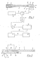
- Fig. 1 zeigt in teilweise schematischer Darstellung eine Einrichtung zur Durchführung des erfindungsgemäßen Verfahrens, Fig. 2 zeigt das Detail eines Koppelelements einer anderen Einrichtung nach der Erfindung, Fig. 3 zeigt das Detail eines anderen Koppelelements einer erfindungsgemäßen Einrichtung mit austauschbarem Adapterteil, Fig. 4 zeigt eine andere Ausführungsform eines Koppelelements einer erfindungsgemäßen Einrichtung und Fig. 5 zeigt eine schematische Anordnung nach der Erfindung zur Durchführung einer statischen Kalibrierung.
- 1 shows a partially schematic representation of a device for carrying out the method according to the invention, FIG. 2 shows the detail of a coupling element of another device according to the invention, FIG. 3 shows the detail of another coupling element of a device according to the invention with an exchangeable adapter part, FIG. 4 shows another embodiment of a coupling element of a device according to the invention and FIG. 5 shows a schematic arrangement according to the invention for carrying out a static calibration.
Die Einrichtung nach Fig. 1 dient zur Bestimmung innenballistischer Kenngrößen in einem Waffenrohr 1, welches beispielsweise auch in einer hier nicht weiter dargestellten Rohrwaffe eingebaut sein kann und bis auf das Koppelelement 2 an der Mündung 3 keinerlei Änderung gegenüber der serienmäßigen Ausführung aufweist. In der Geschoßkammer 4 an dem der Mündung 3 gegenüberliegenden Ende des Waffenrohres 1 ist eine Patrone 5 mit einem Geschoß 6 eingesetzt, dessen Bewegung durch das Waffenrohr 1 im Hinblick auf den Weg/Zeit-Zusammenhang bzw. die jeweilige Geschwindigkeit und Beschleunigung untersucht werden soll.The device according to FIG. 1 is used to determine internal ballistic parameters in a
Zu diesem Zweck wird über zumindest einen, im Bereich des Koppelelementes 2 angeordneten Hohlleiter-Übergang 7 eine elektromagnetische Welle in das Waffenrohr 1 eingekoppelt und nach Reflexion am Geschoß 6 wieder ausgekoppelt, wonach die sich bei einer nderung der Geschoßposition im Waffenrohr ändernde Phasenlage zwischen eingekoppelter und ausgekoppelter Welle als Meßsignal für die Geschoßposition und nach entsprechender Verknüpfung mit der aktuellen Zeit zur Bestimmung von Geschwindigkeit und Beschleunigung verwendet werden kann.For this purpose, an electromagnetic wave is coupled into the
Die in einem Mikrowellengenerator 8 erzeugte elektromagnetische Welle, welche je nach dem Kaliber des Waffenrohres 1 üblicherweise Wellenlängen in Millimeter- bzw. Zentimeterbereich aufweist, wird über ein Koaxialkabel 9 einem Zirkulator 10 zugeführt, von wo sie entsprechend der Funktion desselben über ein weiters Koaxialkabel 11 an einen Koaxial-Hohlleiter-Übergang 12 gelangt. Dort wird beispielsweise eine H-Typ-Welle angeregt, die über den Hohlleiter-Übergang 7 (mit dieser Bezeichnung ist hier und im folgenden immer ein Hohlleiter-Hohlleiter-Übergang zu verstehen) in den einen Rundhohlleiter darstellenden inneren Bereich 13 des Koppelelements 2 gelangt und dabei beispielsweise in die zylindersymmetrische E₀₁-Welle umgewandelt wird. Zufolge der anhand der Fig. 2 nachfolgend noch näher erläuterten Einkoppelung der elektromagnetischen Welle an zumindest zwei beabstandeten Stellen 39 bzw. konkret an den beiden Koppelöffnungen 40, 41 gelangt praktisch die gesamte eingekoppelte elektromagnetische Welle über einen konischen Übergang 15 ins Innere des wiederum einen Rundhohlleiter darstellenden Waffenrohres 1. Dieser konische Übergang 15 ist hier deshalb vorgesehen, um den inneren Bereich 13 mit gegenüber dem Kaliber des Waffenrohres 1 zumindest geringfügig größerem Durchmesser ausführen zu können, ohne an der Übergangsstelle zum Waffenrohr 1 Reflexionen bzw. das Auftreten zusätzlicher, unerwünschter Wellentypen riskieren zu müssen.The electromagnetic wave generated in a
Die von der Spitze des Geschosses 6 reflektierte Welle wird über den Hohlleiter-Übergang 7 wieder ausgekoppelt und gelangt über den Koaxial- Hohlleiter-Übergang 12 und das Koaxialkabel 11 wiederum zum Zirkulator 10, wo sie, bedingt durch das nicht reziproke Verhalten dieses Bauelements von der vom Mikrowellengenerator 8 kommenden Welle abgekoppelt und einem Mischer 16 zugeführt wird. Durch Reflexionen und zufolge einer endlichen Sperrdämpfung des Zirkulators 10 liegt an diesem Mischer 16 auch ein Bruchteil der vom Mikrowellengenerator 8 kommenden Welle an und es kommt daher zu einer Mischung zwischen der ausgesandten und der reflektierten Welle. Am Ausgang 17 des Mischers 16 kann die Phasendifferenz zwischen diesen beiden Wellen bzw. die Dopplerfrequenz abgegriffen werden, die nach entsprechender Verstärkung in einem Verstärker 18 und hier nicht weiter dargestellter A/D-Wandlung für den ganzen zeitlichen Bereich eines Schusses in einem Transientenspeicher 19 abgelegt wird. Über eine Verbindungsleitung 20 ist ein Rechner 21, beispielsweise ein handelsüblicher PC, mit dem Transientenspeicher 19 in Verbindung, der die weitere Verarbeitung besorgt und über eine Leitung 22 mit einer Ausgabeeinheit 23′, beispielsweise einem Plotter, zur Anzeige der Ergebnisse verbunden ist. Zufolge der dargestellten und beschriebenen Art der Ein- bzw. Auskoppelung der elektromagnetischen Welle seitlich am Waffenrohr ist eine völlig zerstörungsfreie Bestimmung der innenballistischen Kenngrößen möglich, bei der das Geschoß 6 das Waffenrohr völlig ungehindert frei verlassen kann, womit jegliche Notwendigkeit zum Ersatz bzw. zur Neujustierung von Teilen der Einrichtung nach jedem Schuß entfällt.The wave reflected from the top of the
Aus der bezüglich des Koppelelementes 2 etwas mehr ins Detail gehenden Fig. 2 ist ersichtlich, daß am Koaxial-Hohlleiter-Übergang 12 ein Antennenstift 42 in das Innere des beispielsweise mit rechteckigem Querschnitt ausgebildeten Hohlleiters 27 ragt, was unter Beachtung der in diesem Zusammenhang dem Fachmann geläufigen Maßnahmen auf einfache Weise die Erzeugung einer elektromagnetischen Welle im Inneren des Hohlleiters 27 ermöglicht. Zufolge eines in der Darstellung links vom Übergang 12 angedeuteten reflektierenden Abschlusses gelangen praktisch 100 % dieser Welle im Hohlleiter 27 nach rechts, werden defakto aufgeteilt und treten über zwei an in Ausbreitungsrichtung der Welle beabstandeten Stellen 39 angeordneten Koppelöffnungen 40, 41 in den inneren Bereich 13 des Koppelelements 2 ein. Die übergekoppelte Spannung wird dabei durch ein elektrisches und/oder ein magnetisches Feld in der Koppelöffnung induziert und ist daher um 90° phasenverschoben. Bei Wahl des richtigen Abstandes L der beiden Koppelöffnungen 40, 41 addieren sich die nach rechts ausbreitenden Wellenanteile, während sich die nach links laufenden Anteile kompensieren. Bei gleicher Ausbreitungsgeschwindigkeit der einzelnen Wellenteile und gleicher Phasenverschiebung an den einzelnen Koppelöffnungen ist diese Kompensation vollständig, wenn der in Längsrichtung des Waffenrohres gemessene Abstand L der einzelnen Koppelöffnungen 40, 41 der Gleichung L = n .λ + λ/4 gehorcht; mit n = natürliche Zahl (0, 1, 2,...), und λ = Wellenlänge.From FIG. 2, which goes into more detail with regard to the
Durch einen in der Darstellung der Fig. 2 am rechten Ende des Hohlleiters 27 angedeuteten reflexionsfreien Abschluß 43 ist sichergestellt, daß rücklaufende Wellenteile im Hohlleiter 27 ausgeschlossen sind, welche die Einkoppelung bzw. die beschriebene Art der Addition und Kompensation stören würden.A reflection-
Die beschriebene Art der Einkoppelung der elektromagnetischen Welle in das Koppelelement 2 bzw. über den konischen Übergang 15 in das Waffenrohr 1 sichert eine große Intensität der in Richtung zum Geschoß 6 laufenden Welle, was in unmittelbarer Folge auch das an der Geschoßspitze reflektierte Signal sehr intensiv sein läßt. Das reflektierte Signal wird unter Umkehrung des beschriebenen Prinzips der Einkoppelung wieder ausgekoppelt, wobei sich nun die Vorteile der in beschriebener Weise aufgeteilten Auskoppelung dahingehend auswirken, daß die ausgekoppelte Welle im Hohlleiter 27 praktisch vollständig nach links läuft, da sich die in Richtung zum reflexionsfreien Abschluß 43 laufenden Anteile wiederum kompensieren.The described way of coupling the electromagnetic wave into the
Das in Fig. 3 dargestellte Koppelelement 2 ist im wesentlichen ähnlich aufgebaut wie die in Fig. 1 bzw. 2 nur schematisch dargestellten, wobei hier jedoch nun der konische Übergang 15 in einem austauschbaren Adapterteil 23 angeordnet ist, der in der Darstellung separat von den übrigen Teilen des Koppelelements gezeichnet ist und auf hier nicht weiter interessante Weise - beispielsweise durch Verschraubung oder mittels Klauenkupplungen - einerseits an der Stirnfläche 24 und andererseits am nicht weiter dargestellten Waffenrohr befestigbar ist. Im Bereich des konischen Überganges 15 des Adapterteils 23 sind nach außen offene schlitzförmige Ausnehmungen 25 über den Umfang verteilt, die einen Druckabbau ermöglichen und natürlich so ausgeführt sein müssen, daß die einlaufende bzw. die reflektierte Welle möglichst wenig gestört wird.The
In dem vom Geschoß beim Abfeuern des Schusses überstrichenen inneren Bereich 13 ist eine, wie beschrieben einen gegenüber dem Rohrkaliber vergrößerten Durchmesser aufweisende, zylindrische Durchgangsausnehmung 26 angeordnet, in welche seitlich die Koppelöffnungen (hier ist nur eine dargestellt und mit 40 bezeichnet) münden. Senkrecht zur Achse des Koppelelements 2 gesehen ist diese Koppelöffnung 40 im wesentlichen rechteckig, wobei hier die schmalen Seiten zufolge der Herstellung durch einen Fingerfräser gerundet sind. Davon abgesehen könnte die Koppelöffnung 40 auch jeden anderen geeigneten Querschnitt aufweisen - auch verschiedene Querschnitte bzw. Größen der einzelnen Koppelöffnungen sind möglich, um das Koppelverhalten zu beeinflussen.Arranged in the
Im Bereich der Stirnfläche 24 ist in Fig. 3 strichliert ein bedarfsweise vorzusehender Boden für den Hohlleiter 27 angedeutet, der dann diesen Hohlleiter tatsächlich zu einem Rechteck-Hohlleiter macht. Davon abgesehen ist aber jede andere geeignete Art bzw. Querschnittsform des Hohlleiters 27 denkbar und im Ermessensbereich des Fachmannes bedarfsweise einsetzbar.In the area of the
Im Bereich der Koppelöffnung 40 ist gemäß Fig. 3 ein Verschlußstück 31 aus elektrisch nichtleitendem Material mit geringen dielektrischen Verlusten angeordnet, welches den Innenraum des Hohlleiters 27 gegen den vom Geschoß überstrichenen Innenbereich hin abschließt und damit das Eindringen von Verschmutzungen bzw. allfällige negative Auswirkungen von verbleibenden Druckwellen unterbindet.In the area of the
In Fig. 4 ist schematisch eine andere Ausführung eines Koppelelements 2′ dargestellt, dessen Hohlleiter-Übergang 7′ durch eine Vielzahl von schlitzförmigen Koppelöffnungen 40′ am Umfang des vom Geschoß überstrichenen inneren Bereichs 13′ gebildet ist. Der Hohlleiter 27′, der beispielsweise wiederum einen hier nicht dargestellten Koaxial-Hohlleiter-Übergang zum Anschluß eines Koaxialkabels aufweisen kann, ist im Bereich des Hohlleiter-Übergangs 7′ abgebogen und parallel zur Achse des inneren Bereichs 13′ verlaufend ausgeführt. Die schlitzförmigen Koppelöffnungen 40′ weisen auch hier wiederum einen von der Wellenlänge der ein- bzw. auszukoppelnden Welle abhängigen Abstand auf, womit wiederum die oben bereits beschriebenen Vorteile erzielbar sind.In Fig. 4 another embodiment of a coupling element 2 'is shown schematically, the waveguide transition 7' is formed by a plurality of slot-shaped coupling openings 40 'on the circumference of the inner region 13' swept by the projectile. The waveguide 27 ', which may in turn have a coaxial waveguide transition, not shown here, for connecting a coaxial cable, is bent in the region of the waveguide transition 7' and runs parallel to the axis of the inner region 13 '. The slot-shaped coupling openings 40 'again have a wavelength of the shaft to be coupled in or out, which in turn achieves the advantages already described above.
Gemäß der schematisch in Fig. 5 dargestellten Anordnung wird zur statischen Kalibrierung eine über eine Schubstange 32 mit einer Wegmeßeinrichtung 33 zusammenwirkende Geschoßatrappe 34 zumindest bereichsweise durch das Waffenrohr 1 bewegt, welches im übrigen hier den Hohlleiter-Übergang 7˝ nicht an einem separaten Koppelelement sondern unmittelbar an den seitlichen Koppelöffnung 40, 41 des Waffenrohres 1 angeordnet hat. Über die dem Koaxialkabel 11 in Fig. 1 entsprechende Leitung 36 erfolgt die Zu- bzw. Ableitung des Signals zum bzw. vom Hohlleiter-Übergang 7˝. Ein der jeweiligen Position der Geschoßatrappe 34 im Waffenrohr 1 entsprechendes Wegsignal liegt über die Leitung 37 an der Einheit 38 an, welche hier sowohl die Auswerteeinheit als auch die Einheit zur Erzeugung der Mikrowellen umfaßt.According to the arrangement shown schematically in FIG. 5, a
Die Geschoßatrappe 34 ist relativ leicht im Waffenrohr 1 hin und her bewegbar, wobei eine genaue Zuordnung zwischen dem wie zu Fig. 1 beschrieben erhaltenen Meßsignal und dem tatsächlichen Weg des Geschosses im Waffenrohr erhalten wird.The
Abgesehen von der dargestellten und besprochenen Ausführung mit jeweils einem einzelnen Hohlleiter-Übergang ist im Rahmen der Erfindung natürlich auch die Anordnung eines weiteren bzw. sogar mehrerer derartiger Übergänge - die jeweils wie beschrieben zumindest zwei Koppelöffnungen aufweisen - am Waffenrohr möglich, wodurch sich auf einfache Weise elektromagnetische Wellen mit verschiedenen Frequenzen jeweils optimal in das Waffenrohr einkoppeln bzw. daraus auskoppeln lassen, sodaß beispielsweise für die unterschiedlichen Phasen der Geschoßbewegung im Waffenrohr unterschiedliche Genauigkeiten erzielt werden können.Apart from the illustrated and discussed embodiment, each with a single waveguide transition, within the scope of the invention it is of course also possible to arrange a further or even several such transitions - each of which has at least two coupling openings as described - on the weapon barrel, which is simple Optimally couple electromagnetic waves with different frequencies into or out of the weapon barrel so that, for example, different accuracies can be achieved for the different phases of the projectile movement in the weapon barrel.
Claims (7)
Applications Claiming Priority (2)
| Application Number | Priority Date | Filing Date | Title |
|---|---|---|---|
| AT0057588A AT389764B (en) | 1988-03-04 | 1988-03-04 | METHOD AND DEVICE FOR DETERMINING INNER BALLISTIC CHARACTERISTICS IN TUBE ARMS |
| AT575/88 | 1988-03-04 |
Publications (1)
| Publication Number | Publication Date |
|---|---|
| EP0331670A1 true EP0331670A1 (en) | 1989-09-06 |
Family
ID=3494217
Family Applications (1)
| Application Number | Title | Priority Date | Filing Date |
|---|---|---|---|
| EP89890058A Withdrawn EP0331670A1 (en) | 1988-03-04 | 1989-02-27 | Method and device to determine the internal ballistic characteristics of guns |
Country Status (5)
| Country | Link |
|---|---|
| US (1) | US4928523A (en) |
| EP (1) | EP0331670A1 (en) |
| JP (1) | JPH0217397A (en) |
| AT (1) | AT389764B (en) |
| DK (1) | DK104689A (en) |
Cited By (3)
| Publication number | Priority date | Publication date | Assignee | Title |
|---|---|---|---|---|
| EP1837618A1 (en) * | 2006-03-21 | 2007-09-26 | Honeywell International, Inc. | Mortar blast attenuator diffuser |
| WO2009141055A1 (en) * | 2008-05-21 | 2009-11-26 | Rheinmetall Air Defence Ag | Device and method for measuring the muzzle velocity of a projectile or similar |
| DE102009030862B3 (en) * | 2009-06-26 | 2010-11-25 | Rheinmetall Air Defence Ag | Method and device for measuring the muzzle velocity of a projectile or the like |
Families Citing this family (18)
| Publication number | Priority date | Publication date | Assignee | Title |
|---|---|---|---|---|
| AT393038B (en) * | 1989-08-28 | 1991-07-25 | Avl Verbrennungskraft Messtech | METHOD AND DEVICE FOR DETERMINING MOTION CHARACTERISTICS |
| US7100437B2 (en) * | 2003-11-24 | 2006-09-05 | Advanced Design Consulting Usa, Inc. | Device for collecting statistical data for maintenance of small-arms |
| US7082823B1 (en) * | 2005-01-14 | 2006-08-01 | Honeywell International, Inc. | Digital signal processing back biased hall effect muzzle velocity measurement system |
| DE102006058375A1 (en) * | 2006-12-08 | 2008-06-12 | Oerlikon Contraves Ag | Method for measuring the muzzle velocity of a projectile or the like |
| US8353121B2 (en) | 2007-05-10 | 2013-01-15 | Leitner-Wise Defense, Inc. | Processes and systems for monitoring usage of projectile weapons |
| US8117778B2 (en) | 2007-05-10 | 2012-02-21 | Robert Bernard Iredale Clark | Processes and systems for monitoring environments of projectile weapons |
| DE102007056633B4 (en) * | 2007-11-24 | 2013-01-17 | Krauss-Maffei Wegmann Gmbh & Co. Kg | barreled weapon |
| EP2411758B1 (en) * | 2009-03-24 | 2017-08-30 | Dynamit Nobel Defence GmbH | Determination of the muzzle velocity of a projectile |
| DE102010006529B4 (en) * | 2010-02-01 | 2013-12-12 | Rheinmetall Air Defence Ag | Method and device for transmitting energy to a projectile |
| DE102010006530B4 (en) * | 2010-02-01 | 2013-12-19 | Rheinmetall Air Defence Ag | Programmable ammunition |
| US9879963B2 (en) | 2013-03-27 | 2018-01-30 | Nostromo Holdings, Llc | Systems to measure yaw, spin and muzzle velocity of projectiles, improve fire control fidelity, and reduce shot-to-shot dispersion in both conventional and airbursting programmable projectiles |
| US9600900B2 (en) | 2013-03-27 | 2017-03-21 | Nostromo Holdings, Llc | Systems to measure yaw, spin and muzzle velocity of projectiles, improve fire control fidelity, and reduce shot-to-shot dispersion in both conventional and air-bursting programmable projectiles |
| US10514234B2 (en) | 2013-03-27 | 2019-12-24 | Nostromo Holdings, Llc | Method and apparatus for improving the aim of a weapon station, firing a point-detonating or an air-burst projectile |
| US11933585B2 (en) | 2013-03-27 | 2024-03-19 | Nostromo Holdings, Llc | Method and apparatus for improving the aim of a weapon station, firing a point-detonating or an air-burst projectile |
| DE102015001413B4 (en) * | 2015-02-06 | 2020-02-27 | Rheinmetall Air Defence Ag | Waveguide arrangement for measuring the speed of a projectile during the passage of a weapon barrel arrangement |
| DE102019134884A1 (en) * | 2019-12-18 | 2021-06-24 | Rheinmetall Air Defence Ag | Detection device and method for the detection of interfering factors in a weapon barrel or loading tube of a barrel weapon |
| WO2021212228A1 (en) | 2020-04-23 | 2021-10-28 | Ultra Electronics Forensic Technology Inc. | Method and system for creating marks on bullets |
| CN115468451B (en) * | 2022-08-29 | 2023-08-29 | 山西华洋吉禄科技股份有限公司 | Device for simulating missile to leave cabin rapidly |
Citations (3)
| Publication number | Priority date | Publication date | Assignee | Title |
|---|---|---|---|---|
| FR976704A (en) * | 1948-10-13 | 1951-03-21 | Comp Generale Electricite | Device for measuring the reflection coefficient of a wave called h01 or te01 in a guide with circular section |
| DE2054583A1 (en) * | 1970-11-06 | 1972-05-10 | Licentia Gmbh | Self-wave selective directional coupler |
| EP0023365A2 (en) * | 1979-07-31 | 1981-02-04 | ARES, Inc. | Doppler-type projectile velocity measurement apparatus and method |
Family Cites Families (6)
| Publication number | Priority date | Publication date | Assignee | Title |
|---|---|---|---|---|
| US2735981A (en) * | 1956-02-21 | Microwave interferometer | ||
| US2691761A (en) * | 1948-02-03 | 1954-10-12 | Jr Nicholas M Smith | Microwave measuring of projectile speed |
| US2679631A (en) * | 1950-10-02 | 1954-05-25 | Rca Corp | Power divider |
| US2748350A (en) * | 1951-09-05 | 1956-05-29 | Bell Telephone Labor Inc | Ultra-high frequency selective mode directional coupler |
| BE754626A (en) * | 1969-08-12 | 1971-01-18 | Oerlikon Buehrle Ag | INSTALLATION DETERMINING THE INITIAL SPEED OF A PROJECTILE |
| US3918061A (en) * | 1973-09-25 | 1975-11-04 | Terma Elektronisk Industri As | Velocity measuring doppler radar |
-
1988
- 1988-03-04 AT AT0057588A patent/AT389764B/en not_active IP Right Cessation
-
1989
- 1989-02-27 EP EP89890058A patent/EP0331670A1/en not_active Withdrawn
- 1989-03-02 JP JP1048703A patent/JPH0217397A/en active Pending
- 1989-03-03 DK DK104689A patent/DK104689A/en not_active Application Discontinuation
- 1989-03-03 US US07/319,098 patent/US4928523A/en not_active Expired - Fee Related
Patent Citations (3)
| Publication number | Priority date | Publication date | Assignee | Title |
|---|---|---|---|---|
| FR976704A (en) * | 1948-10-13 | 1951-03-21 | Comp Generale Electricite | Device for measuring the reflection coefficient of a wave called h01 or te01 in a guide with circular section |
| DE2054583A1 (en) * | 1970-11-06 | 1972-05-10 | Licentia Gmbh | Self-wave selective directional coupler |
| EP0023365A2 (en) * | 1979-07-31 | 1981-02-04 | ARES, Inc. | Doppler-type projectile velocity measurement apparatus and method |
Cited By (6)
| Publication number | Priority date | Publication date | Assignee | Title |
|---|---|---|---|---|
| EP1837618A1 (en) * | 2006-03-21 | 2007-09-26 | Honeywell International, Inc. | Mortar blast attenuator diffuser |
| US7798046B2 (en) | 2006-03-21 | 2010-09-21 | Honeywell International Inc. | Mortar blast attenuator diffuser |
| WO2009141055A1 (en) * | 2008-05-21 | 2009-11-26 | Rheinmetall Air Defence Ag | Device and method for measuring the muzzle velocity of a projectile or similar |
| DE102008024574A1 (en) * | 2008-05-21 | 2010-06-17 | Rheinmetall Air Defence Ag | Apparatus and method for measuring the muzzle velocity of a projectile or the like |
| TWI399514B (en) * | 2008-05-21 | 2013-06-21 | Rheinmetall Air Defence Ag | Apparatus and method for measurement of the muzzle velocity of a projectile or the like |
| DE102009030862B3 (en) * | 2009-06-26 | 2010-11-25 | Rheinmetall Air Defence Ag | Method and device for measuring the muzzle velocity of a projectile or the like |
Also Published As
| Publication number | Publication date |
|---|---|
| DK104689A (en) | 1989-09-05 |
| US4928523A (en) | 1990-05-29 |
| JPH0217397A (en) | 1990-01-22 |
| ATA57588A (en) | 1989-06-15 |
| DK104689D0 (en) | 1989-03-03 |
| AT389764B (en) | 1990-01-25 |
Similar Documents
| Publication | Publication Date | Title |
|---|---|---|
| AT389764B (en) | METHOD AND DEVICE FOR DETERMINING INNER BALLISTIC CHARACTERISTICS IN TUBE ARMS | |
| DE964693C (en) | Microwave directional coupler | |
| DE102010006528B4 (en) | Method and device for programming a projectile | |
| DE1079138B (en) | Waveguide directional coupler | |
| EP0108973B1 (en) | Apparatus for measuring the muzzle velocity of a projectile fired by a weapon | |
| EP1241469A2 (en) | Microwave resonator device for measurements on tobacco | |
| WO2000075645A2 (en) | Stray field probe | |
| DE19629593A1 (en) | Arrangement for generating and transmitting microwaves, especially for a level measuring device | |
| DE1591214A1 (en) | Antenna system for an approach radar device | |
| DE2408610C3 (en) | Horn antenna | |
| DE3317215A1 (en) | Method of quantitatively determining particles in samples | |
| DE2917794A1 (en) | RESONATOR FOR ELECTRONIC SPIN RESONANCE EXPERIMENTS | |
| DE3726046C2 (en) | ||
| DE3316328A1 (en) | MICROWAVE MEASURING DEVICE FOR THE EMPTY SPACE IN A LIQUID FLOW | |
| DE102009030862B3 (en) | Method and device for measuring the muzzle velocity of a projectile or the like | |
| EP3254120B1 (en) | Waveguide arrangement for measuring the speed of a projectile during passage through a weapon barrel arrangement | |
| EP1895290B1 (en) | Microwave measuring device for determining at least one measured value on a product | |
| DE102016013220B3 (en) | Microwave measuring arrangement for determining the loading of a two-phase flow | |
| EP0971213B1 (en) | Microwave content level measurement apparatus with improved signal quality | |
| DE1069233B (en) | ||
| AT393038B (en) | METHOD AND DEVICE FOR DETERMINING MOTION CHARACTERISTICS | |
| WO1996024838A1 (en) | Process for determining the solids content of a gas flow | |
| DE2156065A1 (en) | MICROWAVE INTERFEROMETER AND PROCEDURE FOR ITS OPERATION | |
| DE2344627A1 (en) | Speed measuring device for vehicles and aircraft - using doppler shift of electromagnetic waves, uses waveguide | |
| DE1491358A1 (en) | Device for phase focusing of charged particles |
Legal Events
| Date | Code | Title | Description |
|---|---|---|---|
| PUAI | Public reference made under article 153(3) epc to a published international application that has entered the european phase |
Free format text: ORIGINAL CODE: 0009012 |
|
| AK | Designated contracting states |
Kind code of ref document: A1 Designated state(s): CH DE FR GB IT LI SE |
|
| 17P | Request for examination filed |
Effective date: 19900302 |
|
| 17Q | First examination report despatched |
Effective date: 19910321 |
|
| STAA | Information on the status of an ep patent application or granted ep patent |
Free format text: STATUS: THE APPLICATION IS DEEMED TO BE WITHDRAWN |
|
| 18D | Application deemed to be withdrawn |
Effective date: 19911001 |