EP0331247A2 - Gas-/Flüssigkeit-Kontaktvorrichtung - Google Patents
Gas-/Flüssigkeit-Kontaktvorrichtung Download PDFInfo
- Publication number
- EP0331247A2 EP0331247A2 EP89200448A EP89200448A EP0331247A2 EP 0331247 A2 EP0331247 A2 EP 0331247A2 EP 89200448 A EP89200448 A EP 89200448A EP 89200448 A EP89200448 A EP 89200448A EP 0331247 A2 EP0331247 A2 EP 0331247A2
- Authority
- EP
- European Patent Office
- Prior art keywords
- gas
- tube
- swirl
- liquid
- gas outlet
- Prior art date
- Legal status (The legal status is an assumption and is not a legal conclusion. Google has not performed a legal analysis and makes no representation as to the accuracy of the status listed.)
- Granted
Links
Images
Classifications
-
- B—PERFORMING OPERATIONS; TRANSPORTING
- B01—PHYSICAL OR CHEMICAL PROCESSES OR APPARATUS IN GENERAL
- B01D—SEPARATION
- B01D3/00—Distillation or related exchange processes in which liquids are contacted with gaseous media, e.g. stripping
- B01D3/14—Fractional distillation or use of a fractionation or rectification column
- B01D3/16—Fractionating columns in which vapour bubbles through liquid
- B01D3/18—Fractionating columns in which vapour bubbles through liquid with horizontal bubble plates
- B01D3/20—Bubble caps; Risers for vapour; Discharge pipes for liquid
Definitions
- the present invention relates to a gas/liquid contacting apparatus comprising a housing provided with a gas inlet, a liquid outlet, a liquid inlet and a gas outlet arranged above the gas inlet, and a horizontal tray arranged between the gas inlet and the liquid inlet and provided with a cyclonic separator extending from below the horizontal tray to above the horizontal tray, which cyclonic separator comprises a vertical swirl tube internally provided with swirl imparting means, a coaxial gas outlet tube arranged above the vertical swirl tube, an outer tube arranged around the swirl tube so as to define an annular space between the swirl tube and the outer tube opening below the tray, a passage communicating between the interior of the swirl tube above the swirl imparting means and the annular space, and at least one conduit extending from the exterior of the cyclonic separator above the tray to the interior of the swirl tube below the swirl imparting means, wherein the outer tube is provided at its upper end with a closed cover.
- gas is supplied to the gas inlet and liquid is supplied to the liquid inlet.
- Gas flows upwards through the gas/liquid contacting apparatus and liquid flows downwards through the apparatus.
- Liquid is collected on the tray and flows through the conduit(s) to the interior of the swirl tube below the swirl imparting means where it is brought in contact with the gas.
- the mixture of gas and liquid passes upwards through the vertical swirl tube internally provided with swirl imparting means.
- liquid is separated from the gas/liquid mixture.
- the liquid is collected on the inner surface of the vertical swirl tube above the swirl imparting means and flows through the passage into the annular space between the outer tube and the swirl tube. Liquid leaves the annular space below the tray and leaves the gas/liquid contacting apparatus through the liquid outlet. Gas, from which liquid has been removed, passes through the coaxial gas outlet tube to the gas outlet above the tray, through which gas leaves the gas/liquid contacting apparatus.
- Such a gas/liquid contacting apparatus can be operated at an entrainment level below 5% of the volumetric flow rate of the liquid as supplied on the tray for volumetric flow rates of the liquid below 5 m3/hour at relatively low volumetric flow rates of the gas.
- the gas/liquid contacting apparatus comprises a housing provided with a gas inlet, a liquid outlet, a liquid inlet and a gas outlet arranged above the gas inlet, and a horizontal tray arranged between the gas inlet and the liquid inlet and provided with a cyclonic separator extending from below the horizontal tray to above the horizontal tray, which cyclonic separator comprises a vertical swirl tube internally provided with swirl imparting means, a coaxial gas outlet tube arranged near the upper part of the vertical swirl tube, an outer tube arranged around the swirl tube so as to define an annular space between the swirl tube and the outer tube opening below the tray, a passage communicating between the interior of the swirl tube above the swirl imparting means and the annular space, and at least one conduit extending from the exterior of the cyclonic separator above the tray to the interior of the swirl tube below the swirl imparting means, wherein the coaxial gas outlet tube is externally provided with an annular deflector, and wherein the outer tube is provided at its upper end with an annular cover of which the
- gas is entrained with the liquid flowing through the passage into the annular space. This gas flows out of the annular space through the gas outlet. Gas flowing out of the gas outlet is deflected by the annular deflector attached to the gas outlet conduit before the gas flows upwards to the gas outlet of the gas/liquid contacting apparatus. Liquid entrained with the gas is separated from the gas when the gas is deflected by the annular deflector; this liquid is then returned to the tray where it joins with the liquid supplied to the tray through the liquid inlet of the gas/liquid contacting apparatus.
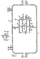
- the gas/liquid contacting apparatus 1 comprises a housing 2 provided with a gas inlet 3 and a liquid outlet 5 which are arranged at the lower part of the housing 2, and a liquid inlet 7 and a gas outlet 9 which are arranged above the gas inlet 3.
- the housing 2 is further provided with a horizontal tray 11 arranged between the gas inlet 3 and the liquid inlet 7.
- the horizontal tray 11 is provided with a cyclonic separator 13 extending from below the horizontal tray 11 to above the horizontal tray 11.
- the cyclonic separator 13 comprises a vertical swirl tube 17 internally provided with swirl imparting means 19, a coaxial gas outlet tube 21 arranged near the upper part of the vertical swirl tube 17, an outer tube 23 arranged around the swirl tube 17 so as to define an annular space 25 between the outer wall of the swirl tube 17 and the inner wall of the outer tube 23 opening below the tray 11.
- the cyclonic separator 13 further comprises a passage 27 communicating between the interior of the swirl tube 17 above the swirl imparting means 19 and the annular space 25, and conduits 31 extending from the exterior of the cyclonic separator 13 above the tray 11 to the interior of the swirl tube 17 below the swirl imparting means 19.
- the coaxial gas outlet tube 21 is externally provided with an annular deflector 32, and the outer tube 23 is provided at its upper end with a gas outlet 33 debouching below the annular deflector 32 and with an annular cover 35 of which the inner edge 36 is located around the gas outlet tube 21 below the annular deflector 32, wherein the gas outlet 33 is the slit between the inner edge 36 and the outer wall of the gas outlet 21.
- gas is supplied to the gas inlet 3 and liquid is supplied to the liquid inlet 7.
- Gas flows upwards through the gas/liquid contacting apparatus 1 and liquid flows downwards through the apparatus 1.
- Liquid is collected on the tray 11 and flows through the conduits 31 to the interior of the swirl tube 17 below the swirl imparting means 19 where it is brought in contact with the gas.
- the mixture of gas and liquid passes upwards through the vertical swirl tube 17 internally provided with swirl imparting means 19.
- the liquid is separated from the gas/liquid mixture.
- the liquid is collected on the inner surface of the vertical swirl tube 17 above the swirl imparting means 19 and flows through the passage 27 into the annular space 25 between the outer tube 23 and the swirl tube 17.
- Liquid leaves the annular space 25 below the tray 11 and leaves the gas/liquid contacting apparatus 1 through the liquid outlet 5.
- Gas, from which liquid has been removed, passes through the coaxial gas outlet tube 21 to the gas outlet 9, through which gas leaves the gas/liquid contacting apparatus 1.
- the gas flow is deflected by the annular deflector 32 attached to the gas outlet conduit 21 before the gas flows upwards to the gas outlet 9 of the gas/liquid contacting apparatus 1.
- Liquid entrained with the gas is separated from the gas when the flow is deflected by the annular deflector 32 and this liquid is then returned to the tray 11 where it is combined with the liquid supplied to the tray 11 through the liquid inlet 7 of the gas/liquid contacting apparatus 1.
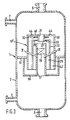
- FIG. 3 showing an alternative design of the gas/liquid contacting apparatus according to the invention.
- similar parts of the apparatus have been given the same reference numerals as in Figure 1, and for the sake of clarity not all parts have been given a reference numeral.
- the tray 11 of the gas/liquid contacting apparatus 1 is provided with a cyclonic separator 13′, which cyclonic separator 13′ further comprises a second outer tube 40 which is arranged around the outer tube 23 so as to define an open-ended second annular space 42 which opens below the tray 11.
- the second outer tube 40 is provided at its upper end with gas outlets 44 and with an annular cover 46 of which the inner edge is located around the gas outlet tube above the annular deflector 32.
- the lower end of the swirl tube 17 is provided with a sealing pan 50 of which the side walls extend to the lower surface of the tray 11.
- the sealing pan has an outlet (not shown) which is in fluid communication with the liquid outlet 5.
- the sealing pan 50 prevents during normal operation gas flowing upwards through the annular spaces 25 and 42. Which is particularly relevant during start-up.
- gas is supplied to the gas inlet 3 and liquid is supplied to the liquid inlet 7.
- Gas flows upwards through the gas/liquid contacting apparatus 1 and liquid flows downwards through the apparatus 1.
- Liquid is collected on the tray 11 and flows through the conduit 31 to the interior of the swirl tube 17 below the swirl imparting means 19 where it is brought in contact with the gas.
- the mixture of gas and liquid passes upwards through the vertical swirl tube 17 internally provided with swirl imparting means 19.
- the swirl imparted to the mixture by the swirl imparting means 19 liquid is separated from the gas/liquid mixture.
- the liquid is collected on the inner surface of the vertical swirl tube 17 above the swirl imparting means 19 and flows through the passage 27 into the annular space 25 between the outer tube 23 and the swirl tube 17.
- Liquid leaves the annular space 25 below the tray 11 and flows into the sealing pan 50, from where it is discharged.
- the liquid leaves the gas/liquid contacting apparatus 1 through the liquid outlet 5.
- Gas, from which liquid has been removed, passes through the coaxial gas outlet tube 21 to the gas outlet 9, through which gas leaves the gas/liquid contacting apparatus 1.
- the gas flow is deflected by the annular deflector 32 attached to the gas outlet conduit 21 before the gas flows upwards to the gas outlet 9 of the gas/liquid contacting apparatus 1.
- Liquid entrained with the gas is separated from the gas when the flow is deflected by the annular deflector 32. This liquid flows through the annular space 42 into the sealing pan 50. Gas entrained with the liquid can leave the annular space 42 through outlets 44.
- the gas outlets 44 can be replaced by a gas outlet defined between the inner edge of the annular cover pertaining to the second outer tube and the coaxial gas outlet tube.
- the cyclonic separators 13 and 13′ have not been drawn to scale.
- the inner diameter of the gas outlet tube 21 is between 0.5 and 1.0 times the inner diameter of the swirl tube 17, and more suitably between 0.7 and 0.9 times the inner diameter of the swirl tube 17.
- the inner diameter of the outer tube 23 is between 1.1 and 2.0 times the outer diameter of the swirl tube 17, and suitably between 1.2 and 1.4 times the outer diameter of the swirl tube 17.
- the inner diameter of the swirl tube 17 is between 50 and 150 mm, and the wall thickness of the swirl tube 17, of the gas outlet tube 21 and of the outer tube 23 are between 0.5 and 3 mm.
- the overall length of the cyclonic separator 13 is between 300 and 900 mm, and suitably between 450 and 600 mm. This large length of the cyclonic separator allows a large height above the tray 11 which is required to maintain, during normal operation, a sufficient liquid level on the tray so that liquid can flow through the conduits 31 at a sufficiently large flow rate into the swirl tube 17.
- the lower end of the coaxial gas outlet tube 21 is arranged between 20 mm below the upper end of the swirl tube 17 and 60 mm above the upper end of the swirl tube 17.
- the inner diameter of the second outer tube 40 is between 1.05 and 1.25 times the outer diameter of the outer tube 23.
- FIG. 1 and 3 Shown in Figures 1 and 3 is a gas/liquid contacting apparatus comprising one tray which is provided with one cyclonic separator.
- the apparatus may be provided with a plurality of trays, each of which trays is provided with a plurality of cyclonic separators.
- cyclonic separators When a tray is provided with a plurality of cyclonic separators the cyclonic separators will be arranged in rows. In this case sealing pans of a row of cyclonic separators can be combined in the form of a gutter.
- the gas/liquid contacting apparatus according to the invention can suitably be used for removing undesired components, such as hydrogen sulphide, from a gas mixture by contacting the gas mixture with a liquid absorbent for these undesired components.
- undesired components such as hydrogen sulphide
- the gas/liquid contacting apparatus can form the stripping section and/or the enrichment section of a distillation column.
- the tests were carried out with a single tray provided with a single cyclonic separator.
- the liquid was kerosine, and the gas nitrogen.
- the liquid was separately collected.
- the volumetric flow rate of the liquid as supplied through the liquid inlet was varied until the liquid entrainment rate was 5% of volumetric flow rate of the liquid.
- a cyclonic separator as shown in Figure 1 was tested.
- the dimensions of the cyclonic separator were: inner diameter of the outer tube 150 mm, inner diameter of the swirl tube 110 mm, inner diameter of the gas outlet 90 mm, overall length of the cyclonic separator 475 mm, and distance between the lower end of the gas outlet tube and the upper end of the swirl tube 30 mm.
- the gas outlet tube was provided with an annular deflector arranged at 25 mm above the upper end of the outer tube and having a diameter of 130 mm.
- the upper end of the outer tube was provided with a gas outlet in the form of a slit having a width of 5 mm.
- the cyclonic separator was provided with a sealing pan of the kind as shown in Figure 2.
- the swirl tube was provided with swirl imparting means in the form of 6 blades.
- the cyclonic separator as used in the first test was provided with a second outer tube as shown in Figure 2.
- the inner diameter of the second outer tube was 170 mm.
- the upper end of the second outer tube was arranged 25 mm above the annular deflector and was provided with a gas outlet in the form of a slit having a width of 24 mm.
- the swirl tube was provided with swirl imparting means in the form of 6 blades.
- a cyclonic separator was tested which was not provided with an annular deflector, nor was the upper end of the outer tube provided with a gas outlet.
- the dimensions of the cyclonic separator were: inner diameter of the outer tube 130 mm, inner diameter of the swirl tube 110 mm, inner diameter of the gas outlet 85 mm, overall length of the cyclonic separator 290 mm, and distance between the lower end of the gas outlet tube and the upper end of the swirl tube 40 mm.
- the swirl tube was provided with swirl imparting means in the form of 4 blades.
- the cyclonic separator according to the invention can be operated at higher liquid volumetric flow rates with an entrainment of 5% and at higher gas volumetric flow rates than the cyclonic separator not provided with an annular deflector and wherein the upper end of the outer tube of the cyclonic separator was not provided with a gas outlet.
Landscapes
- Chemical & Material Sciences (AREA)
- Chemical Kinetics & Catalysis (AREA)
- Separating Particles In Gases By Inertia (AREA)
Applications Claiming Priority (3)
| Application Number | Priority Date | Filing Date | Title |
|---|---|---|---|
| GB888805115A GB8805115D0 (en) | 1988-03-03 | 1988-03-03 | Gas/liquid contacting apparatus |
| GB8805115 | 1988-03-03 | ||
| CA000594442A CA1326812C (en) | 1988-03-03 | 1989-03-22 | Gas/liquid contacting apparatus |
Publications (3)
| Publication Number | Publication Date |
|---|---|
| EP0331247A2 true EP0331247A2 (de) | 1989-09-06 |
| EP0331247A3 EP0331247A3 (en) | 1990-01-24 |
| EP0331247B1 EP0331247B1 (de) | 1992-11-25 |
Family
ID=25672541
Family Applications (1)
| Application Number | Title | Priority Date | Filing Date |
|---|---|---|---|
| EP89200448A Expired - Lifetime EP0331247B1 (de) | 1988-03-03 | 1989-02-22 | Gas-/Flüssigkeit-Kontaktvorrichtung |
Country Status (3)
| Country | Link |
|---|---|
| US (1) | US4880451A (de) |
| EP (1) | EP0331247B1 (de) |
| CA (1) | CA1326812C (de) |
Cited By (5)
| Publication number | Priority date | Publication date | Assignee | Title |
|---|---|---|---|---|
| EP0364117A3 (de) * | 1988-10-08 | 1991-05-15 | The British Petroleum Company P.L.C. | Verfahren zum Vermischen von Dämpfen in einer Gegenstrom-Kolonne |
| EP0562689A1 (de) * | 1992-03-25 | 1993-09-29 | Shell Internationale Researchmaatschappij B.V. | Vorrichtung zum Kontaktieren von Gas-Flüssigkeit im Gegenstrom |
| RU2150990C1 (ru) * | 1999-06-28 | 2000-06-20 | Дочернее открытое акционерное общество "Центральное конструкторское бюро нефтеаппаратуры" Открытого акционерного общества "Газпром" | Колонна для проведения массообменных процессов |
| US7841585B2 (en) | 2003-02-21 | 2010-11-30 | Shell Oil Company | Separation tray |
| CN110358595A (zh) * | 2019-07-30 | 2019-10-22 | 四川长仪油气集输设备股份有限公司 | 一种高效多级旋风加捕雾分离器 |
Families Citing this family (14)
| Publication number | Priority date | Publication date | Assignee | Title |
|---|---|---|---|---|
| AU684157B2 (en) * | 1994-03-24 | 1997-12-04 | Shell Internationale Research Maatschappij B.V. | Column for counter-currently contacting gas and liquid |
| US5865995A (en) * | 1997-04-02 | 1999-02-02 | Nelson; William R. | System for treating liquids with a gas |
| US7001448B1 (en) | 2001-06-13 | 2006-02-21 | National Tank Company | System employing a vortex finder tube for separating a liquid component from a gas stream |
| US6576029B2 (en) | 2001-06-13 | 2003-06-10 | National Tank Company | System for separating an entrained liquid component from a gas stream |
| US6514322B2 (en) | 2001-06-13 | 2003-02-04 | National Tank Company | System for separating an entrained immiscible liquid component from a wet gas stream |
| US6629686B2 (en) * | 2001-06-25 | 2003-10-07 | Dwain E. Morse | Process for dissolving gas into a liquid |
| US6673135B2 (en) | 2002-02-08 | 2004-01-06 | National Tank Company | System and method of separating entrained immiscible liquid component of an inlet stream |
| JP3957706B2 (ja) * | 2003-06-11 | 2007-08-15 | 金 斗年 | 放熱管への電熱線挿入方法とその装置、及びその端部の密閉装置 |
| US7473405B2 (en) * | 2004-10-13 | 2009-01-06 | Chevron U.S.A. Inc. | Fluid distribution apparatus for downflow multibed poly-phase catalytic reactor |
| RU2287359C2 (ru) * | 2004-11-30 | 2006-11-20 | Открытое акционерное общество "Минерально-химическая компания "ЕвроХим"(ОАО "МХК "ЕвроХим") | Вихревой аппарат для проведения физико-химических процессов с нисходящим потоком фаз |
| JP3890076B1 (ja) * | 2006-02-03 | 2007-03-07 | 修 松本 | 気泡発生装置 |
| WO2008030456A1 (en) * | 2006-09-06 | 2008-03-13 | Optimal Ozone Outcomes Pty Ltd | Apparatus for treating a liquid with a gas |
| US7811344B1 (en) | 2007-12-28 | 2010-10-12 | Bobby Ray Duke | Double-vortex fluid separator |
| US8608833B2 (en) | 2010-06-09 | 2013-12-17 | Uop Llc | Selective absorption of gas components in co-current contacting apparatuses |
Family Cites Families (21)
| Publication number | Priority date | Publication date | Assignee | Title |
|---|---|---|---|---|
| US1094107A (en) * | 1912-08-29 | 1914-04-21 | Atmospheric Clarifier Co | Air-washer. |
| US1123232A (en) * | 1913-10-15 | 1915-01-05 | Hermann A Brassert | Gas-washing. |
| US1121868A (en) * | 1914-02-11 | 1914-12-22 | Standard Motor Construction Company | Gas-generator for internal-combustion engines. |
| US1362025A (en) * | 1919-07-31 | 1920-12-14 | Yuba Mfg Company | Spark-arrester |
| US1511749A (en) * | 1920-08-18 | 1924-10-14 | James A Powell | Combination heater |
| GB630823A (en) * | 1947-09-25 | 1949-10-21 | Otto Ludvig Blaedel Westergaar | Improvements in or relating to cooling towers |
| US2808897A (en) * | 1953-05-22 | 1957-10-08 | Exxon Research Engineering Co | Apparatus for contacting liquid and vaporous materials |
| US2970671A (en) * | 1953-12-17 | 1961-02-07 | Otto P Warner | Separator for removing liquids and solids from vapors |
| US2881858A (en) * | 1954-06-21 | 1959-04-14 | Svenska Flaektfabriken Ab | Apparatus for separating dust or liquid drops from a gaseous medium |
| US2864463A (en) * | 1955-07-29 | 1958-12-16 | Centrifix Corp | Internal purifier |
| US2890870A (en) * | 1957-10-23 | 1959-06-16 | Joseph W Spiselman | Apparatus for contacting liquids and gases |
| GB902223A (en) * | 1958-06-24 | 1962-08-01 | Chiyoda Chem Eng Construct Co | Gas-liquid contact apparatus |
| BE636933A (de) * | 1962-09-05 | |||
| FR1444377A (fr) * | 1965-06-25 | 1966-07-01 | Ilikon Corp | Appareil pour le préchauffage de matières à mouler |
| GB1172680A (en) * | 1967-12-29 | 1969-12-03 | Shell Int Research | Apparatus for Contacting Liquids and Gases. |
| US3546851A (en) * | 1968-12-20 | 1970-12-15 | Universal Oil Prod Co | Gas scrubbing apparatus |
| US3566582A (en) * | 1969-04-04 | 1971-03-02 | Entoleter | Mass contact between media of different densities |
| SU856501A1 (ru) * | 1979-10-30 | 1981-08-23 | Kiselev Viktor M | Газожидкостный сепаратор |
| CA1188978A (en) * | 1981-02-03 | 1985-06-18 | Richard C. Darton | Column for treating gases |
| US4566883A (en) * | 1983-04-08 | 1986-01-28 | Shell Oil Company | Apparatus for gas/liquid separation |
| GB8601359D0 (en) * | 1986-01-21 | 1986-02-26 | Shell Int Research | Contacting gas & liquid |
-
1989
- 1989-02-10 US US07/308,488 patent/US4880451A/en not_active Expired - Lifetime
- 1989-02-22 EP EP89200448A patent/EP0331247B1/de not_active Expired - Lifetime
- 1989-03-22 CA CA000594442A patent/CA1326812C/en not_active Expired - Fee Related
Cited By (6)
| Publication number | Priority date | Publication date | Assignee | Title |
|---|---|---|---|---|
| EP0364117A3 (de) * | 1988-10-08 | 1991-05-15 | The British Petroleum Company P.L.C. | Verfahren zum Vermischen von Dämpfen in einer Gegenstrom-Kolonne |
| EP0562689A1 (de) * | 1992-03-25 | 1993-09-29 | Shell Internationale Researchmaatschappij B.V. | Vorrichtung zum Kontaktieren von Gas-Flüssigkeit im Gegenstrom |
| US5300132A (en) * | 1992-03-25 | 1994-04-05 | Shell Oil Company | Contacting device |
| RU2150990C1 (ru) * | 1999-06-28 | 2000-06-20 | Дочернее открытое акционерное общество "Центральное конструкторское бюро нефтеаппаратуры" Открытого акционерного общества "Газпром" | Колонна для проведения массообменных процессов |
| US7841585B2 (en) | 2003-02-21 | 2010-11-30 | Shell Oil Company | Separation tray |
| CN110358595A (zh) * | 2019-07-30 | 2019-10-22 | 四川长仪油气集输设备股份有限公司 | 一种高效多级旋风加捕雾分离器 |
Also Published As
| Publication number | Publication date |
|---|---|
| EP0331247B1 (de) | 1992-11-25 |
| EP0331247A3 (en) | 1990-01-24 |
| US4880451A (en) | 1989-11-14 |
| CA1326812C (en) | 1994-02-08 |
Similar Documents
| Publication | Publication Date | Title |
|---|---|---|
| EP0331247B1 (de) | Gas-/Flüssigkeit-Kontaktvorrichtung | |
| US4767424A (en) | Column for removing liquid from a gas | |
| US4349360A (en) | Fluid treating column and apparatus for treating mixtures of liquid and gas | |
| CA1124660A (en) | Down flow centrifugal separator | |
| US3304694A (en) | Gas-liquid contactor with central supply conduit | |
| US4187089A (en) | Horizontal vapor-liquid separator | |
| US3546851A (en) | Gas scrubbing apparatus | |
| JP2006518274A (ja) | 分離トレイ | |
| CA2196067C (en) | Column for contacting gas and liquid | |
| US2986278A (en) | Centrifugal separators | |
| US4755198A (en) | Column for treating gases | |
| KR880001992B1 (ko) | 기액 혼합물로 부터의 액체 분리를 위한 수직 분리탑 | |
| US5300132A (en) | Contacting device | |
| US2087219A (en) | Method amd apparatus fok cleaning | |
| US6105941A (en) | Vapor/liquid contacting cyclone with device to prevent backmixing and process for using the same | |
| KR930020485A (ko) | 원자로 기밀실의 공기의 에어러솔의 제거장치 | |
| AU686441B2 (en) | Column for contacting gas and liquid | |
| CA1134283A (en) | Separation of a suspension of two immiscible fluids | |
| AU606268B2 (en) | Gas/liquid contacting apparatus | |
| US2765870A (en) | Apparatus for separation of entrained liquid from gases | |
| SU1745302A1 (ru) | Сепаратор дл отделени жидкости от газа | |
| SU985550A1 (ru) | Отводчик жидкости | |
| JPS594418A (ja) | ミスト除去装置 |
Legal Events
| Date | Code | Title | Description |
|---|---|---|---|
| PUAI | Public reference made under article 153(3) epc to a published international application that has entered the european phase |
Free format text: ORIGINAL CODE: 0009012 |
|
| AK | Designated contracting states |
Kind code of ref document: A2 Designated state(s): CH DE GB LI NL |
|
| PUAL | Search report despatched |
Free format text: ORIGINAL CODE: 0009013 |
|
| AK | Designated contracting states |
Kind code of ref document: A3 Designated state(s): CH DE GB LI NL |
|
| 17P | Request for examination filed |
Effective date: 19900523 |
|
| 17Q | First examination report despatched |
Effective date: 19911118 |
|
| GRAA | (expected) grant |
Free format text: ORIGINAL CODE: 0009210 |
|
| AK | Designated contracting states |
Kind code of ref document: B1 Designated state(s): CH DE GB LI NL |
|
| REF | Corresponds to: |
Ref document number: 68903579 Country of ref document: DE Date of ref document: 19930107 |
|
| PLBE | No opposition filed within time limit |
Free format text: ORIGINAL CODE: 0009261 |
|
| STAA | Information on the status of an ep patent application or granted ep patent |
Free format text: STATUS: NO OPPOSITION FILED WITHIN TIME LIMIT |
|
| 26N | No opposition filed | ||
| PGFP | Annual fee paid to national office [announced via postgrant information from national office to epo] |
Ref country code: GB Payment date: 20010123 Year of fee payment: 13 |
|
| PGFP | Annual fee paid to national office [announced via postgrant information from national office to epo] |
Ref country code: NL Payment date: 20010227 Year of fee payment: 13 |
|
| PGFP | Annual fee paid to national office [announced via postgrant information from national office to epo] |
Ref country code: DE Payment date: 20010320 Year of fee payment: 13 |
|
| PGFP | Annual fee paid to national office [announced via postgrant information from national office to epo] |
Ref country code: CH Payment date: 20010430 Year of fee payment: 13 |
|
| REG | Reference to a national code |
Ref country code: GB Ref legal event code: IF02 |
|
| PG25 | Lapsed in a contracting state [announced via postgrant information from national office to epo] |
Ref country code: GB Free format text: LAPSE BECAUSE OF NON-PAYMENT OF DUE FEES Effective date: 20020222 |
|
| PG25 | Lapsed in a contracting state [announced via postgrant information from national office to epo] |
Ref country code: LI Free format text: LAPSE BECAUSE OF NON-PAYMENT OF DUE FEES Effective date: 20020228 Ref country code: CH Free format text: LAPSE BECAUSE OF NON-PAYMENT OF DUE FEES Effective date: 20020228 |
|
| PG25 | Lapsed in a contracting state [announced via postgrant information from national office to epo] |
Ref country code: NL Free format text: LAPSE BECAUSE OF NON-PAYMENT OF DUE FEES Effective date: 20020901 |
|
| PG25 | Lapsed in a contracting state [announced via postgrant information from national office to epo] |
Ref country code: DE Free format text: LAPSE BECAUSE OF NON-PAYMENT OF DUE FEES Effective date: 20020903 |
|
| GBPC | Gb: european patent ceased through non-payment of renewal fee |
Effective date: 20020222 |
|
| REG | Reference to a national code |
Ref country code: CH Ref legal event code: PL |
|
| NLV4 | Nl: lapsed or anulled due to non-payment of the annual fee |
Effective date: 20020901 |