EP0331062B2 - Sammelleitung zum Aufnehmen von Gasströmen aus einer Mehrzahl von parallel arbeitenden Einheiten - Google Patents
Sammelleitung zum Aufnehmen von Gasströmen aus einer Mehrzahl von parallel arbeitenden Einheiten Download PDFInfo
- Publication number
- EP0331062B2 EP0331062B2 EP89103367A EP89103367A EP0331062B2 EP 0331062 B2 EP0331062 B2 EP 0331062B2 EP 89103367 A EP89103367 A EP 89103367A EP 89103367 A EP89103367 A EP 89103367A EP 0331062 B2 EP0331062 B2 EP 0331062B2
- Authority
- EP
- European Patent Office
- Prior art keywords
- manifold
- main channel
- channel
- parallel
- connection
- Prior art date
- Legal status (The legal status is an assumption and is not a legal conclusion. Google has not performed a legal analysis and makes no representation as to the accuracy of the status listed.)
- Expired - Lifetime
Links
- JTJMJGYZQZDUJJ-UHFFFAOYSA-N phencyclidine Chemical class C1CCCCN1C1(C=2C=CC=CC=2)CCCCC1 JTJMJGYZQZDUJJ-UHFFFAOYSA-N 0.000 claims description 13
- 208000016791 bilateral striopallidodentate calcinosis Diseases 0.000 claims description 6
- 238000000746 purification Methods 0.000 claims description 3
- 238000011144 upstream manufacturing Methods 0.000 claims description 2
- 239000007789 gas Substances 0.000 description 13
- 238000002485 combustion reaction Methods 0.000 description 4
- 239000000567 combustion gas Substances 0.000 description 3
- 238000004140 cleaning Methods 0.000 description 2
- 239000000428 dust Substances 0.000 description 2
- 239000000446 fuel Substances 0.000 description 2
- 239000003380 propellant Substances 0.000 description 2
- 239000003245 coal Substances 0.000 description 1
- 238000011161 development Methods 0.000 description 1
- 230000018109 developmental process Effects 0.000 description 1
- 230000001747 exhibiting effect Effects 0.000 description 1
- 239000000463 material Substances 0.000 description 1
- 239000011236 particulate material Substances 0.000 description 1
- 238000000926 separation method Methods 0.000 description 1
Images
Classifications
-
- B—PERFORMING OPERATIONS; TRANSPORTING
- B04—CENTRIFUGAL APPARATUS OR MACHINES FOR CARRYING-OUT PHYSICAL OR CHEMICAL PROCESSES
- B04C—APPARATUS USING FREE VORTEX FLOW, e.g. CYCLONES
- B04C5/00—Apparatus in which the axial direction of the vortex is reversed
- B04C5/24—Multiple arrangement thereof
- B04C5/28—Multiple arrangement thereof for parallel flow
-
- B—PERFORMING OPERATIONS; TRANSPORTING
- B01—PHYSICAL OR CHEMICAL PROCESSES OR APPARATUS IN GENERAL
- B01D—SEPARATION
- B01D45/00—Separating dispersed particles from gases or vapours by gravity, inertia, or centrifugal forces
- B01D45/12—Separating dispersed particles from gases or vapours by gravity, inertia, or centrifugal forces by centrifugal forces
-
- F—MECHANICAL ENGINEERING; LIGHTING; HEATING; WEAPONS; BLASTING
- F15—FLUID-PRESSURE ACTUATORS; HYDRAULICS OR PNEUMATICS IN GENERAL
- F15D—FLUID DYNAMICS, i.e. METHODS OR MEANS FOR INFLUENCING THE FLOW OF GASES OR LIQUIDS
- F15D1/00—Influencing flow of fluids
- F15D1/001—Flow of fluid from conduits such as pipes, sleeves, tubes, with equal distribution of fluid flow over the evacuation surface
-
- F—MECHANICAL ENGINEERING; LIGHTING; HEATING; WEAPONS; BLASTING
- F23—COMBUSTION APPARATUS; COMBUSTION PROCESSES
- F23C—METHODS OR APPARATUS FOR COMBUSTION USING FLUID FUEL OR SOLID FUEL SUSPENDED IN A CARRIER GAS OR AIR
- F23C10/00—Fluidised bed combustion apparatus
- F23C10/16—Fluidised bed combustion apparatus specially adapted for operation at superatmospheric pressures, e.g. by the arrangement of the combustion chamber and its auxiliary systems inside a pressure vessel
-
- F—MECHANICAL ENGINEERING; LIGHTING; HEATING; WEAPONS; BLASTING
- F23—COMBUSTION APPARATUS; COMBUSTION PROCESSES
- F23J—REMOVAL OR TREATMENT OF COMBUSTION PRODUCTS OR COMBUSTION RESIDUES; FLUES
- F23J15/00—Arrangements of devices for treating smoke or fumes
- F23J15/02—Arrangements of devices for treating smoke or fumes of purifiers, e.g. for removing noxious material
- F23J15/022—Arrangements of devices for treating smoke or fumes of purifiers, e.g. for removing noxious material for removing solid particulate material from the gasflow
- F23J15/027—Arrangements of devices for treating smoke or fumes of purifiers, e.g. for removing noxious material for removing solid particulate material from the gasflow using cyclone separators
-
- Y—GENERAL TAGGING OF NEW TECHNOLOGICAL DEVELOPMENTS; GENERAL TAGGING OF CROSS-SECTIONAL TECHNOLOGIES SPANNING OVER SEVERAL SECTIONS OF THE IPC; TECHNICAL SUBJECTS COVERED BY FORMER USPC CROSS-REFERENCE ART COLLECTIONS [XRACs] AND DIGESTS
- Y10—TECHNICAL SUBJECTS COVERED BY FORMER USPC
- Y10T—TECHNICAL SUBJECTS COVERED BY FORMER US CLASSIFICATION
- Y10T137/00—Fluid handling
- Y10T137/8593—Systems
- Y10T137/85938—Non-valved flow dividers
-
- Y—GENERAL TAGGING OF NEW TECHNOLOGICAL DEVELOPMENTS; GENERAL TAGGING OF CROSS-SECTIONAL TECHNOLOGIES SPANNING OVER SEVERAL SECTIONS OF THE IPC; TECHNICAL SUBJECTS COVERED BY FORMER USPC CROSS-REFERENCE ART COLLECTIONS [XRACs] AND DIGESTS
- Y10—TECHNICAL SUBJECTS COVERED BY FORMER USPC
- Y10T—TECHNICAL SUBJECTS COVERED BY FORMER US CLASSIFICATION
- Y10T137/00—Fluid handling
- Y10T137/8593—Systems
- Y10T137/87571—Multiple inlet with single outlet
Definitions
- the invention relates to a manifold for receiving gas streams from a plurality of parallel-working units according to the introductory part of claim 1.
- the manifold is primarily intended to receive purified gas from gas cleaners operating in parallel, for example cyclones in a PFBC power plant in which the combustion gases from a combustor are utilized for operation of one or more gas turbines.
- PFBC are the initial letters of the English expression "Pressurized Fluidized Bed Combustion”.
- the invention aims at designing a manifold of the above-mentioned kind exhibiting equalized pressure conditions on its inflow connections.
- a uniform load in parallel-working cleaners is obtained by a special embodiment of the connecting channel from a cleaner to the main channel of the manifold.
- the connection channel is parallel to the manifold main channel, and the cross-sectional area of this channel is such that the velocity of flow becomes the same as in the main channel.
- the area of the manifold main channel increases with the area of the connection channel.
- the length of the connection channel, which is parallel to the manifold main channel is at least equal to the diameter of a tube having the same area as the channel. Suitably, the length is more than twice this diameter.
- the manifold may consist of a number of tubes having diameters increasing in steps.
- a connecting tube projects into a tube which is enlarged at the connection.
- the connection channel is formed by the gap between this enlarged tube and the tube projecting thereinto.
- the connection channel may consist of a tube which is substantially parallel to a tube forming a part of the main channel. The area of the main channel tube increases with the area of the connecting tube at the mouth of the connecting tube.
- a number of groups of series-connected cyclones are connected to the manifold.
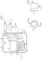
- 10 designates a pressure vessel.
- the pressure vessel 10 comprises a combustor 12 and a gas purification plant 13 comprising a plurality of parallel groups of series-connected cyclones 14 and 16 for purifying the combustion gases. Only one such group is shown in Figure 1 while four such groups are to be seen in Figures 2 and 3.
- the space 18 inside the pressure vessel 10 and surrounding the combustor 12 contains compressed combustion air. The pressure may amount to 2 MPa or more.
- Combustion air is supplied to the combustor 12 via nozzles 20 in the air-distributing bottom 22. This air fluidizes a bed 24 of particulate material and burns a fuel, usually coal. Fuel and bed material are supplied to the bed 24 via the feed pipe 26.
- the combustor 12 includes tubes 28 for the generation of steam for a steam turbine (not shown).
- the combustion gases are collected in the freeboard 30 above the bed 24 and are passed to the cyclones 14 and 16 via the pipes 32 and 34.
- the last cyclones 16a to 16d in the groups of parallel-connected cyclones 14, 16 are connected to a manifold 35.
- This manifold 35 consists of tubes 36a-d and tubes 38a-d forming the inlet channels 40b-40d and the main channel, respectively.
- the tube 38d of the manifold 35 is connected to a tube supplying propellant gas to the turbine 42.
- the turbine 42 drives a compressor 44, which supplies the space 18 with compressed combustion air, and a generator 46.
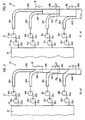
- the purification plant 13 consists of parallel groups of cyclones 14a-d and 16a-d which are connected to the combustor 12 by the pipes 32a-d and which are connected between themselves by pipes 34a-d.
- the cyclones 16a-d are connected to the tubes 36a-d forming the inlet channels of the manifold 35 each having the area A.
- the tube parts 38a-d form the main channel of the manifold 35 with the areas A, 2A, 3A and 4A.
- the velocity of flow V becomes equal in the whole main channel of the manifold formed by said tubes parts 38a-d.
- the main channel of the manifold 35 consists of tube parts 38a-d having circular cross-section.
- the first tube part 38a of the pipe 38 projects into the second tube part 38b by a distance L1
- the second tube part 38b projects into the third tube part 38c by a distance L2
- the third tube part 38c projects into the fourth tube part 38d by a distance L3.
- gaps 40b, 40c and 40d are formed, the lengths L1, L2, L3, etc., of which increase with the area of the tube parts 38b-d at the connection.
- the tube parts 36b, 36c and 36d are connected to theses gaps.
- the gaps 40b-d form channels, parallel to the main channel of the manifold 35 ahead of the terminating point of the gaps 40b-d.
- connection channels and the main channel of the manifold 35 consist of rectangular tubes 36a-d and rectangular tubes 38a-d, respectively.
- the tube parts 36b-d are formed parallel to the tube parts 38a-d.
- the area of the main channel formed by the tube parts 38a-d increases with the area of the tube parts 36b-d.
Landscapes
- Engineering & Computer Science (AREA)
- Mechanical Engineering (AREA)
- General Engineering & Computer Science (AREA)
- Chemical & Material Sciences (AREA)
- Chemical Kinetics & Catalysis (AREA)
- Physics & Mathematics (AREA)
- Fluid Mechanics (AREA)
- Combustion & Propulsion (AREA)
- Cyclones (AREA)
- Vaporization, Distillation, Condensation, Sublimation, And Cold Traps (AREA)
- Fluidized-Bed Combustion And Resonant Combustion (AREA)
- Separating Particles In Gases By Inertia (AREA)
Claims (5)
- Sammelleitung zum Aufnehmen von Gasströmen aus einer Mehrzahl von parallel arbeitenden Einheiten mit Verbindungskanälen (40b - 40d), die sich parallel oder im wesentlichen parallel zu einem sammelnden Hauptkanal (38) erstrecken, vorzugsweise in einer Zyklon-Gasreinigungsanlage (14, 16), dadurch gekennzeichnet,daß die genannten Verbindungskanäle (40b - 40d) längs des sammelnden Hauptkanals (38) angeordnet sind,daß die Austrittsöffnungen der Verbindungskanäle (40b - 40d) in den Hauptkanal (38) voneinander getrennt und längs der Länge der Sammelleitung (35) angeordnet sind unddaß die Querschnittsfläche des Hauptkanals (38) sich in solchem Maße vergrößert, daß die Gasgeschwindigkeit V in den Verbindungskanälen (40b - 40d) und dem Hauptkanal (38) im wesentlichen gleich groß ist.
- Sammelleitung nach Anspruch 1, dadurch gekennzeichnet, daß die Länge (L) des Verbindungskanals (40) mindestens gleich dem Durchmesser (d) eines Rohres ist, welches den gleichen Querschnitt wie der Verbindungskanal (40) hat, vorzugsweise mehr als doppelt so groß wie der genannte Durchmesser (d).
- Sammelleitung nach einem der Ansprüche 1 oder 2, dadurch gekennzeichnet, daß die Sammelleitung (35) aus einer Anzahl von Rohrteilen (38a - 38d) mit einer sich graduell vergrößernden Querschnittsfläche an dem Punkte besteht, an dem ein stromaufwärts liegendes Rohrteil sich in einen anschließenden stromabwärts liegenden Rohrteil um eine Länge (L) hineinerstreckt, und daß der der Verbindungskanal (40) von dem Spalt zwischen den beiden Rohrteilen gebildet wird.
- Sammelleitung nach einem der Ansprüche 1 oder 2, dadurch gekennzeichnet, daß der Verbindungskanal (40) aus einem Rohr besteht, welches parallel zu dem Hauptkanal (38) verläuft, und daß die Fläche des Hauptkanals (38) um die Fläche des Verbindungskanals (40) an dessen Mündung in den Hauptkanal (38) größer wird.
- Sammelleitung nach einem der vorhergehenden Ansprüche, dadurch gekennzeichnet, daß sie gereinigtes Gas aus einer Anzahl von Gasreinigern (14, 16) sammelt, vorzugsweise Zyklonen zur Reinigung von Gas aus einer Brennkammer (12) eines PFBC-Kraftwerks.
Applications Claiming Priority (2)
| Application Number | Priority Date | Filing Date | Title |
|---|---|---|---|
| SE8800697 | 1988-02-29 | ||
| SE8800697A SE466837B (sv) | 1988-02-29 | 1988-02-29 | Samlingsledning foer mottagande av gasstroemmar fraan parallellt anordnade grupper av gasrenare |
Publications (4)
| Publication Number | Publication Date |
|---|---|
| EP0331062A2 EP0331062A2 (de) | 1989-09-06 |
| EP0331062A3 EP0331062A3 (de) | 1991-01-09 |
| EP0331062B1 EP0331062B1 (de) | 1993-12-29 |
| EP0331062B2 true EP0331062B2 (de) | 1998-08-12 |
Family
ID=20371524
Family Applications (1)
| Application Number | Title | Priority Date | Filing Date |
|---|---|---|---|
| EP89103367A Expired - Lifetime EP0331062B2 (de) | 1988-02-29 | 1989-02-25 | Sammelleitung zum Aufnehmen von Gasströmen aus einer Mehrzahl von parallel arbeitenden Einheiten |
Country Status (9)
| Country | Link |
|---|---|
| US (1) | US4934407A (de) |
| EP (1) | EP0331062B2 (de) |
| JP (1) | JPH01249924A (de) |
| CA (1) | CA1302839C (de) |
| DE (1) | DE68911711T3 (de) |
| DK (1) | DK170985B1 (de) |
| ES (1) | ES2051904T5 (de) |
| FI (1) | FI96187C (de) |
| SE (1) | SE466837B (de) |
Cited By (1)
| Publication number | Priority date | Publication date | Assignee | Title |
|---|---|---|---|---|
| US12502646B2 (en) | 2021-02-17 | 2025-12-23 | Illinois Tool Works Inc. | Mixing fluids in welding-type equipment |
Families Citing this family (3)
| Publication number | Priority date | Publication date | Assignee | Title |
|---|---|---|---|---|
| NO314469B1 (no) * | 2001-06-25 | 2003-03-24 | Alstom Technology Ltd | Fremgangsmåte og anordning for gasstransport |
| US12011786B2 (en) | 2020-03-11 | 2024-06-18 | Illinois Tool Works Inc. | Smart manifolds for welding-type systems |
| US11938574B2 (en) | 2021-01-22 | 2024-03-26 | Illinois Tool Works Inc. | Gas surge prevention using improved flow regulators in welding-type systems |
Family Cites Families (16)
| Publication number | Priority date | Publication date | Assignee | Title |
|---|---|---|---|---|
| GB189518745A (en) * | 1895-10-07 | 1896-08-15 | Reeves Patent Filters Company | Improvements in and connected with Pipes for Conducting and Distributing Liquids. |
| GB199684A (en) * | 1922-03-23 | 1923-06-25 | William Muir Oddie | Improvements in or relating to apparatus for separating dust and the like from air and gases |
| BE486584A (de) * | 1948-01-02 | |||
| DE1078999B (de) * | 1958-02-22 | 1960-04-07 | Camag Chemie Erzeugnisse | Verfahren zum Abtrennen eines loesbaren, von einer koernigen Adsorptionsmasse adsorbierten Stoffs |
| GB894417A (en) * | 1959-01-28 | 1962-04-18 | Hermann Jaeckering | Centrifugal separators for separating or grading solid mixtures |
| CH383738A (de) * | 1960-06-22 | 1964-10-31 | Hochuli Rene | Gasentstaubungsanlage |
| FR1351028A (fr) * | 1963-03-06 | 1964-01-31 | Escher Wyss Ag | Culotte d'embranchement pour conduites forcées |
| US3507301A (en) * | 1966-04-21 | 1970-04-21 | Robert H Larson | Collector and method of making the same |
| US3543931A (en) * | 1968-02-29 | 1970-12-01 | Nichols Eng & Res Corp | Multiple cyclone assembly |
| US3794056A (en) * | 1972-11-17 | 1974-02-26 | R Warren | Fluidic pulse and flow divider |
| DE2755257A1 (de) * | 1977-12-12 | 1979-06-13 | Didier Eng | Zyklonabscheidevorrichtung |
| JPS5885322A (ja) * | 1981-11-10 | 1983-05-21 | カ−テイス−ライト・コ−ポレ−シヨン | ガスタ−ビン発電プラントの安全制御装置 |
| US4460390A (en) * | 1982-09-30 | 1984-07-17 | Donaldson Company, Inc. | Two stage air cleaner with side-by-side elements |
| US4600414A (en) * | 1982-10-13 | 1986-07-15 | Solar Turbines Incorporated | Apparatus for removing contaminants from heated gases |
| SE457560B (sv) * | 1984-06-13 | 1989-01-09 | Abb Stal Ab | Saett att taenda en braennkammare med en fluidiserad baedd och kraftanlaeggning foer utnyttjande av saettet |
| GB2167321B (en) * | 1984-11-27 | 1987-12-09 | Hibass Photomec Ltd | Cyclone separator |
-
1988
- 1988-02-29 SE SE8800697A patent/SE466837B/sv not_active IP Right Cessation
-
1989
- 1989-02-21 DK DK079189A patent/DK170985B1/da active
- 1989-02-24 CA CA000592093A patent/CA1302839C/en not_active Expired - Fee Related
- 1989-02-24 US US07/314,741 patent/US4934407A/en not_active Expired - Fee Related
- 1989-02-25 EP EP89103367A patent/EP0331062B2/de not_active Expired - Lifetime
- 1989-02-25 ES ES89103367T patent/ES2051904T5/es not_active Expired - Lifetime
- 1989-02-25 DE DE68911711T patent/DE68911711T3/de not_active Expired - Fee Related
- 1989-02-27 JP JP1043418A patent/JPH01249924A/ja active Pending
- 1989-02-28 FI FI890961A patent/FI96187C/fi not_active IP Right Cessation
Cited By (1)
| Publication number | Priority date | Publication date | Assignee | Title |
|---|---|---|---|---|
| US12502646B2 (en) | 2021-02-17 | 2025-12-23 | Illinois Tool Works Inc. | Mixing fluids in welding-type equipment |
Also Published As
| Publication number | Publication date |
|---|---|
| DE68911711T3 (de) | 1999-04-29 |
| SE8800697L (sv) | 1989-08-30 |
| DK79189D0 (da) | 1989-02-21 |
| EP0331062A3 (de) | 1991-01-09 |
| FI96187B (fi) | 1996-02-15 |
| CA1302839C (en) | 1992-06-09 |
| EP0331062A2 (de) | 1989-09-06 |
| DK79189A (da) | 1989-08-30 |
| FI890961L (fi) | 1989-08-30 |
| US4934407A (en) | 1990-06-19 |
| SE466837B (sv) | 1992-04-13 |
| ES2051904T5 (es) | 1999-02-16 |
| DE68911711D1 (de) | 1994-02-10 |
| FI890961A0 (fi) | 1989-02-28 |
| JPH01249924A (ja) | 1989-10-05 |
| ES2051904T3 (es) | 1994-07-01 |
| DE68911711T2 (de) | 1994-07-14 |
| DK170985B1 (da) | 1996-04-15 |
| EP0331062B1 (de) | 1993-12-29 |
| SE8800697D0 (sv) | 1988-02-29 |
| FI96187C (fi) | 1996-05-27 |
Similar Documents
| Publication | Publication Date | Title |
|---|---|---|
| US6269778B1 (en) | Fine solids recycle in a circulating fluidized bed | |
| EP0483173B1 (de) | Vorrichtung zur Abtrennung von teilchenförmigem Material aus heissen Gasen | |
| EP0233630B1 (de) | Kraftwerk mit einem Wirbelbett zum Verbrennen von Brennstoff | |
| EP0331062B2 (de) | Sammelleitung zum Aufnehmen von Gasströmen aus einer Mehrzahl von parallel arbeitenden Einheiten | |
| US5601788A (en) | Combined cycle power plant with circulating fluidized bed reactor | |
| CN87104041A (zh) | 流化床反应器 | |
| US4756257A (en) | Power plant with centrifugal type cleaners for combustion gases | |
| GB2164391A (en) | A gas turbine with a particle separator for the working gas | |
| JP2549094B2 (ja) | 輸送装置 | |
| US5391211A (en) | Integral cylindrical cyclone and loopseal | |
| EP0494650A2 (de) | Verfahren und Vorrichtung zur Abscheidung von Partikeln aus warmen Gas | |
| US4936716A (en) | Transport device for pneumatically transporting particulate material from a container under high pressure to a container under low pressure | |
| SU1318306A1 (ru) | Батарейный циклон | |
| JP3009217B2 (ja) | 空気移送系統のコンベヤ用転移チャンバ | |
| RU2094093C1 (ru) | Установка пылеочистки газовых выбросов (варианты) | |
| SU833328A1 (ru) | Батарейный циклон | |
| DK161871B (da) | Cyklon | |
| CA1121743A (en) | Gas/particle separating device | |
| RU96105476A (ru) | Установка пылеочистки газовых выбросов (варианты) | |
| RU1813579C (ru) | Батарейный циклон | |
| JPH04502746A (ja) | 空気移送系統のコンベヤ用転移チャンバ |
Legal Events
| Date | Code | Title | Description |
|---|---|---|---|
| PUAI | Public reference made under article 153(3) epc to a published international application that has entered the european phase |
Free format text: ORIGINAL CODE: 0009012 |
|
| AK | Designated contracting states |
Kind code of ref document: A2 Designated state(s): DE ES GB |
|
| PUAL | Search report despatched |
Free format text: ORIGINAL CODE: 0009013 |
|
| AK | Designated contracting states |
Kind code of ref document: A3 Designated state(s): DE ES GB |
|
| 17P | Request for examination filed |
Effective date: 19910607 |
|
| 17Q | First examination report despatched |
Effective date: 19930128 |
|
| GRAA | (expected) grant |
Free format text: ORIGINAL CODE: 0009210 |
|
| AK | Designated contracting states |
Kind code of ref document: B1 Designated state(s): DE ES GB |
|
| REF | Corresponds to: |
Ref document number: 68911711 Country of ref document: DE Date of ref document: 19940210 |
|
| REG | Reference to a national code |
Ref country code: ES Ref legal event code: FG2A Ref document number: 2051904 Country of ref document: ES Kind code of ref document: T3 |
|
| K1C1 | Correction of patent application (title page) published |
Effective date: 19890906 |
|
| K2C1 | Correction of patent specification (title page) published |
Effective date: 19931229 |
|
| PLBI | Opposition filed |
Free format text: ORIGINAL CODE: 0009260 |
|
| 26 | Opposition filed |
Opponent name: EVT ENERGIE UND VERFAHRENSTECHNIK GMBH Effective date: 19940928 |
|
| PLAW | Interlocutory decision in opposition |
Free format text: ORIGINAL CODE: EPIDOS IDOP |
|
| PLAW | Interlocutory decision in opposition |
Free format text: ORIGINAL CODE: EPIDOS IDOP |
|
| PUAH | Patent maintained in amended form |
Free format text: ORIGINAL CODE: 0009272 |
|
| STAA | Information on the status of an ep patent application or granted ep patent |
Free format text: STATUS: PATENT MAINTAINED AS AMENDED |
|
| 27A | Patent maintained in amended form |
Effective date: 19980812 |
|
| AK | Designated contracting states |
Kind code of ref document: B2 Designated state(s): DE ES GB |
|
| REG | Reference to a national code |
Ref country code: ES Ref legal event code: DC2A Kind code of ref document: T5 Effective date: 19981112 |
|
| PGFP | Annual fee paid to national office [announced via postgrant information from national office to epo] |
Ref country code: ES Payment date: 19990222 Year of fee payment: 11 |
|
| PGFP | Annual fee paid to national office [announced via postgrant information from national office to epo] |
Ref country code: DE Payment date: 19991231 Year of fee payment: 12 |
|
| PGFP | Annual fee paid to national office [announced via postgrant information from national office to epo] |
Ref country code: GB Payment date: 20000223 Year of fee payment: 12 |
|
| PG25 | Lapsed in a contracting state [announced via postgrant information from national office to epo] |
Ref country code: GB Free format text: LAPSE BECAUSE OF NON-PAYMENT OF DUE FEES Effective date: 20010225 |
|
| PG25 | Lapsed in a contracting state [announced via postgrant information from national office to epo] |
Ref country code: ES Free format text: LAPSE BECAUSE OF NON-PAYMENT OF DUE FEES Effective date: 20010226 |
|
| GBPC | Gb: european patent ceased through non-payment of renewal fee |
Effective date: 20010225 |
|
| PG25 | Lapsed in a contracting state [announced via postgrant information from national office to epo] |
Ref country code: DE Free format text: LAPSE BECAUSE OF NON-PAYMENT OF DUE FEES Effective date: 20011201 |
|
| REG | Reference to a national code |
Ref country code: ES Ref legal event code: FD2A Effective date: 20021016 |