EP0331005A2 - Device for ventilating a room - Google Patents
Device for ventilating a room Download PDFInfo
- Publication number
- EP0331005A2 EP0331005A2 EP89103158A EP89103158A EP0331005A2 EP 0331005 A2 EP0331005 A2 EP 0331005A2 EP 89103158 A EP89103158 A EP 89103158A EP 89103158 A EP89103158 A EP 89103158A EP 0331005 A2 EP0331005 A2 EP 0331005A2
- Authority
- EP
- European Patent Office
- Prior art keywords
- electric motor
- switch
- run
- control device
- housing
- Prior art date
- Legal status (The legal status is an assumption and is not a legal conclusion. Google has not performed a legal analysis and makes no representation as to the accuracy of the status listed.)
- Withdrawn
Links
Images
Classifications
-
- F—MECHANICAL ENGINEERING; LIGHTING; HEATING; WEAPONS; BLASTING
- F24—HEATING; RANGES; VENTILATING
- F24F—AIR-CONDITIONING; AIR-HUMIDIFICATION; VENTILATION; USE OF AIR CURRENTS FOR SCREENING
- F24F11/00—Control or safety arrangements
- F24F11/0001—Control or safety arrangements for ventilation
-
- F—MECHANICAL ENGINEERING; LIGHTING; HEATING; WEAPONS; BLASTING
- F24—HEATING; RANGES; VENTILATING
- F24F—AIR-CONDITIONING; AIR-HUMIDIFICATION; VENTILATION; USE OF AIR CURRENTS FOR SCREENING
- F24F13/00—Details common to, or for air-conditioning, air-humidification, ventilation or use of air currents for screening
- F24F13/08—Air-flow control members, e.g. louvres, grilles, flaps or guide plates
- F24F13/10—Air-flow control members, e.g. louvres, grilles, flaps or guide plates movable, e.g. dampers
- F24F13/14—Air-flow control members, e.g. louvres, grilles, flaps or guide plates movable, e.g. dampers built up of tilting members, e.g. louvre
- F24F13/15—Air-flow control members, e.g. louvres, grilles, flaps or guide plates movable, e.g. dampers built up of tilting members, e.g. louvre with parallel simultaneously tiltable lamellae
Definitions
- the invention relates to a device for ventilating a room, in particular a toilet, consisting of a fan wheel which is arranged in a housing and can be driven by an electric motor which can be connected as required.
- a device for actuating a fan provided with a flap in which the flap is opened by a heating bimetallic strip and is held in the open position in the heated state.
- the flap When the bimetal strip cools, the flap returns to its closed position.
- an electrical heating element which is in heat-conducting contact with the bimetal strip. Since the heating of the heating element and thus the bimetallic strip takes place relatively slowly, the electric motor that drives the fan wheel must be switched on with a delay.
- a special thermal switch is provided in the circuit of the fan motor, which is in heat-conducting contact with the bimetal strip.
- the circuit for the electric motor of the fan wheel is closed.
- the bimetal strip and the thermal switch cool down again.
- the temperature switch opens, the power supply to the electric motor is interrupted and the fan wheel is stopped.
- the delay of the electric motor when switching on and off is dependent on the heating and cooling of the thermal switch and thus on the heating and cooling of the heating element.
- the invention is therefore based on the object of providing a device for ventilating a room, in particular a toilet, which takes effect immediately or within a very short time when an operating switch is actuated and in which the run-on time of the electric motor can be set precisely to a predetermined value or is changeable.
- a digital follow-up control device with a circuit breaker (TRIAC) for the electric motor which can be controlled by a switch or a button is arranged in the housing.
- TRIAC circuit breaker
- This arrangement has the advantage that the electric motor starts immediately when the operating switch is closed and comes into effect immediately when the fan flaps are opened.
- the run-on control device enables a precise setting of the run-on time of the electric motor, the run-on time being changeable.
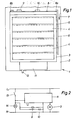
- FIG. 1 of the drawing shows a device 1 which is used, for example, to ventilate a toilet.
- This device 1 consists of a base plate 2, with which the device 1 is fastened in a known manner, not shown, in the region of a ventilation opening or the like.
- the base plate 2 carries an electric motor 3 (FIG. 2) with a fan wheel on its rear side.
- a frame 3 On the front or front side of the base plate 2, a frame 3 is provided, in which a plurality of fan flaps 4 are pivotally mounted about axes, not shown.
- each axis of a fan flap 4 is connected to a lever 5, all of the levers 5 being connected to a common rod 6. By moving the rod 6 in the direction of arrow 7, all fan flaps 4 can be moved from their closed position to an open position.
- the rod 6 is connected at one end to the free end 8a of a bimetallic strip 8, which is clamped in place at its other end 8b.
- the bimetal strip 8 carries a heating element 9, which is designed as a PTC resistor element or PTC resistor.
- a second heating element 10 which is designed in the same way as the heating element 9.
- a housing is provided on the base plate 2, which connects to the lower side of the frame 3 and accommodates a digital run-on control device with a circuit breaker (TRIAC).
- the run-on control device has one adjustable timer, which is provided with an adjusting lever 12.
- the operating switch 13 can be formed by a light switch, a door contact or a button.
- the operating switch 13 When the device 1 is started up, the operating switch 13 is first closed. On the one hand, this causes the room lighting 14 to be switched on. On the other hand, this closes the circuits for the run-on control device and the two heating elements 9, 10.
- the circuit breaker is immediately effective via the run-on control device, thus releasing the circuit for the electric motor 3 so that the fan wheel starts up immediately.
- the heating elements 9, 10 become hot within a very short time and heat the bimetallic strip 8, which is deformed by the heat, so that all the fan flaps 4 are opened via the rod 6.
- the opening process of the ventilation flaps 4 is completed by the two heating elements 9, 10 at the latest after 10 seconds, so that the ventilation is then fully effective.
- the digital run-on control unit works on the basis of a number comparison stage. Appropriate programming specifies a numerical value. By opening the shop switch 13, the digital run-on control device is activated, counts and adds pulses and switches off the circuit breaker (TRIAC) and thus the electric motor 3 when the predetermined / given numerical value is reached. The time that the electric motor 3 should run on can thus be set very precisely. If necessary, this time can be set using the lever 12 of a timer assigned to the run-on control device.
- TRIAC circuit breaker
- the room lighting 14 is switched off and the circuit to the heating elements 9, 10 is also interrupted.
- the heating elements 9, 10 and the bimetallic strip 8 can now cool down.
- all fan flaps 4 are closed.
- the run-on time of the electric motor 3 is expediently chosen so that it switches off approximately simultaneously with the closing of the fan flap 4.
Abstract
Description
Die Erfindung bezieht sich auf eine Vorrichtung zum Belüften eines Raumes, insbesondere einer Toilette, bestehend aus einem in einem Gehäuse angeordneten und von einem bedarfsweise anschaltbaren Elektromotor antreibbaren Lüfterrad.The invention relates to a device for ventilating a room, in particular a toilet, consisting of a fan wheel which is arranged in a housing and can be driven by an electric motor which can be connected as required.
Aus der DE-OS 31 00 232 ist eine Vorrichtung zum Betätigen eines mit einer Klappe versehenen Lüfters bekannt, bei der die Klappe durch einen sich erwärmenden Bimetallstreifen geöffnet und im erwärmten Zustand in der Offenstellung gehalten wird. Beim Abkühlen des Bimetallstreifens geht die Klappe wieder in ihre Schließstellung zurück. Zur Erwärmung des Bitmetallstreifens ist derselbe mit einem elektrischen Heizelement versehen, welches mit dem Bimetallstreifen in wärmeleitender Berührung steht. Da die Erwärmung des Heizelementes und damit des Bimetallstreifens verhältnismäßig langsam erfolgt, muß der Elektromotor, der das Lüfterrad antreibt, verzögert angeschaltet werden. Dazu ist im Stromkreis des Lüftermotors ein besonderer Thermoschalter vorgesehen, der in wärmeleitender Berührung mit dem Bimetallstreifen steht. Sobald der Thermoschalter eine Temperatur von beispielsweise 60 Grad Celsius erreicht hat, die Lüfterklappen beginnen dabei sich zu öffnen, wird der Stromkreis für den Elektromotor des Lüfterrades geschlossen. Beim Öffnen des Stromkreises für das Heizelement kühlen der Bimetallstreifen und der Thermoschalter wieder ab. Sobald der Thermoschalter eine Temperatur von beispielsweise 50 Grad Celsius unterschreitet, öffnet der Thermoschalter, die Stromzufuhr zum Elektromotor wird unterbrochen und das Lüfterrad wird stillgesetzt. Bei dieser bekannten Vorrichtung ist die Verzögerung des Elektromotors beim Anschalten und Abschalten von der Erwärmung und der Abkühlung des Thermoschalters und damit von der Erwärmung und Abkühlung des Heizelementes abhängig. Dieses wiederum wird sehr stark von der Umgebungstemperatur beeinflußt, so daß keinerlei genaue Aussage darüber gemacht werden kann, nach welcher Zeit nach Betätigung eines Betriebsschalters, beispielsweise eines Lichtschalters oder Türkontaktes, das Lüfterrad zu starten beginnt und wieder stillsteht. Insbesondere die nicht kontrollierbare Nachlaufzeit des Elektromotors wird in der Praxis als unbefriedigend angesehen.From DE-OS 31 00 232 a device for actuating a fan provided with a flap is known, in which the flap is opened by a heating bimetallic strip and is held in the open position in the heated state. When the bimetal strip cools, the flap returns to its closed position. To heat the bit metal strip, it is provided with an electrical heating element which is in heat-conducting contact with the bimetal strip. Since the heating of the heating element and thus the bimetallic strip takes place relatively slowly, the electric motor that drives the fan wheel must be switched on with a delay. For this purpose, a special thermal switch is provided in the circuit of the fan motor, which is in heat-conducting contact with the bimetal strip. As soon as the thermal switch has reached a temperature of 60 degrees Celsius, for example, the fan flaps begin to open, the circuit for the electric motor of the fan wheel is closed. When the circuit for the heating element is opened, the bimetal strip and the thermal switch cool down again. Once the If the temperature switch falls below a temperature of, for example, 50 degrees Celsius, the temperature switch opens, the power supply to the electric motor is interrupted and the fan wheel is stopped. In this known device, the delay of the electric motor when switching on and off is dependent on the heating and cooling of the thermal switch and thus on the heating and cooling of the heating element. This, in turn, is very strongly influenced by the ambient temperature, so that no precise statement can be made as to the time after which an operating switch, for example a light switch or door contact, starts the fan wheel and stops again. In particular, the uncontrollable run-on time of the electric motor is considered unsatisfactory in practice.
Es ist ferner bekannt, die Einschalt- und Abschaltverzögerung bei einem Elektromotor für ein Lüftungsrad über eine elektrische Kippstufe zu steuern. Dabei wird ein Kondensator über einen Vorwiderstand aufgeladen. Bei Erreichen eines vorgegebenen Spannungswertes am Kondensator schaltet ein Bauelement durch und schließt den Stromkreis zum Elektromotor des Lüfters. Solange der Betriebsschalter geschlossen ist, wird der Kondensator mit Spannung versorgt und hält den Stromkreis des Elektromotors geschlossen. Wird der Betriebsschalter geöffnet, entlädt sich der Kondensator und öffnet beim Erreichen der unteren Kippspannung den Stromkreis für den Elektromotor. Auch bei dieser Steuerung werden die Lüfterklappen über einen mit einen Heizelement bestückten Bimetallstreifen geöffnet, so daß die Vorrichtung erst verhältnismäßig spät nach der Betätigung des Betriebsschalters zur Wirkung kommt. Die elektrische Kippstufe hat den Nachteil, daß der Elektromotor erst verzögert anläuft und daß die Nachlaufzeit nicht kontrollierbar bzw. einstellbar ist.It is also known to control the switch-on and switch-off delay in an electric motor for a ventilation wheel via an electrical flip-flop. A capacitor is charged via a series resistor. When a predetermined voltage value is reached on the capacitor, a component switches through and closes the circuit to the electric motor of the fan. As long as the operating switch is closed, the capacitor is supplied with voltage and keeps the electric motor circuit closed. If the operating switch is opened, the capacitor discharges and opens the circuit for the electric motor when the lower breakover voltage is reached. In this control too, the fan flaps are opened via a bimetallic strip equipped with a heating element, so that the device comes into effect only relatively late after the operating switch has been actuated. The electric flip-flop has the disadvantage that the electric motor only starts after a delay and that the run-on time cannot be controlled or set.
Der Erfindung liegt deshalb die Aufgabe zugrunde, eine Vorrichtung zum Belüften eines Raumes, insbesondere einer Toilette zu schaffen, die mit der Betätigung eines Betriebsschalters sofort bzw. innerhalb kürzester Zeit wirksam wird und bei der die Nachlaufzeit des Elektromotors genau auf einen vorgegebenen Wert einstellbar bzw. veränderbar ist.The invention is therefore based on the object of providing a device for ventilating a room, in particular a toilet, which takes effect immediately or within a very short time when an operating switch is actuated and in which the run-on time of the electric motor can be set precisely to a predetermined value or is changeable.
Zur Lösung dieser Aufgabe wird bei einer Vorrichtung der eingangs beschriebenen Gattung vorgeschlagen, daß in dem Gehäuse ein durch einen Schalter oder einen Taster ansteuerbares, digitales Nachlaufsteuergerät mit einem Leistungsschalter (TRIAC) für den Elektromotor angeordnet ist.To solve this problem, it is proposed in a device of the type described in the introduction that a digital follow-up control device with a circuit breaker (TRIAC) for the electric motor which can be controlled by a switch or a button is arranged in the housing.
Diese Anordnung hat den Vorteil, daß der Elektromotor sofort mit dem Schließen des Betriebsschalters anläuft und sofort beim Öffnen der Lüfterklappen zur Wirkung kommt. Das Nachlaufsteuergerät ermöglicht eine genaue Einstellung der Nachlaufzeit des Elektromotors, wobei die Nachlaufzeit veränderbar ist.This arrangement has the advantage that the electric motor starts immediately when the operating switch is closed and comes into effect immediately when the fan flaps are opened. The run-on control device enables a precise setting of the run-on time of the electric motor, the run-on time being changeable.
Weitere Merkmale der Erfindung sind in den Ansprüchen 2 und 3 offenbart.Further features of the invention are disclosed in
Die Erfindung wird nachfolgend anhand eines in einer Zeichnung dargestellten Ausführungsbeispieles näher erläutert. Dabei zeigen
- Fig. 1 eine Draufsicht auf die offene Frontseite einer Vorrichtung gemäß der Erfindung und
- Fig. 2 einen Schaltplan der Vorrichtung der Fig. 1.
- Fig. 1 is a plan view of the open front of a device according to the invention and
- FIG. 2 is a circuit diagram of the device of FIG. 1.
In der Fig. 1 der Zeichnung ist ein Vorrichtung 1 gezeigt, die beispielsweise zur Belüftung einer Toilette dient. Diese Vorrichtung 1 besteht aus einer Grundplatte 2, mit der die Vorrichtung 1 in an sich bekannter, nicht dargestellter Weise im Bereich einer Entlüftungsöffnung oder dgl. befestigt wird. Die Grundplatte 2 trägt an ihrer Rückseite einen Elektromotor 3 (Fig. 2) mit einem Lüfterrad. An der Vorder- bzw. Frontseite der Grundplatte 2 ist ein Rahmen 3 vorgesehen, in dem mehrere Lüfterklappen 4 über nicht dargestellte Achsen schwenkbar gelagert sind. An einer Seite des rechteckigen Rahmens 3 ist jede Achse einer Lüfterklappe 4 mit einem Hebel 5 verbunden, wobei alle Hebel 5 an eine gemeinsame Stange 6 angeschlossen sind. Durch Verschiebung der Stange 6 in Richtung des Pfeiles 7 können alle Lüfterklappen 4 aus ihrer geschlossen gezeichneten Stellung in eine Offenstellung bewegt werden.1 of the drawing shows a
Zur Bewegung der Spange 6 und damit zur Öffnung der Lüfterklappen 4 ist die Stange 6 an einem Ende mit dem freien Ende 8a eines Bimetallstreifens 8 verbunden, der mit seinem anderen Ende 8b ortsfest eingespannt ist. Nahe dem eingespannten Ende 8b trägt der Bimetallstreifen 8 ein Heizelement 9, welches als Kaltleiterelement bzw. PTC-Widerstand ausgebildet ist. Etwa in der Mitte zwischen dem Heizelement 9 und dem freien Ende 8a des Bimetallstreifens 8 befindet sich ein zweites Heizelement 10, welches in gleicher Weise wie das Heizelement 9 ausgebildet ist.To move the
Auf der Grundplatte 2 ist ferner ein Gehäuse vorgesehen, welches sich an der unteren Seite des Rahmens 3 anschließt und ein digitales Nachlaufsteuergerät mit einem Leistungsschalter (TRIAC) aufnimmt. Dabei weist das Nachlaufsteuergerät einen einstellbaren Zeitschalter auf, der mit einem Stellhebel 12 versehen ist.Furthermore, a housing is provided on the
Der Fig. 2 ist zu entnehmen, daß die Phase L einer Netzspannung von 220 Volt über den Leistungsschalter im Gehäuse 11 zum Motor 3 geführt ist und andererseits über einen Betriebsschalter 13 an dem Nachlaufsteuergerät, den Heizelementen 9 und 10 sowie einer Raumbeleuchtung 14 anliegt, deren anderer Anschluß, in gleicher Weise wie der Elektromotor 3, mit dem Null-Potential N verbunden ist. Der Betriebsschalter 13 kann dabei durch einen Lichtschalter, einen Türkontakt oder einen Taster gebildet sein.2 that the phase L of a mains voltage of 220 volts is led to the
Bei der Inbetriebnahme der Vorrichtung 1 wird zunächst der Betriebsschalter 13 geschlossen. Dadurch wird einerseits die Raumbeleuchtung 14 angeschaltet. Andererseits werden dadurch die Stromkreise für das Nachlaufsteuergerät und die beiden Heizelemente 9,10 geschlossen. Über das Nachlaufsteuergerät wird sofort der Leistungsschalter wirksam, der damit den Stromkreis für den Elektromotor 3 freigibt, so daß das Lüfterrad sofort anläuft. Die Heizelemente 9,10 werden innerhalb kürzester Zeit heiß und beheizen den Bimetallstreifen 8, der sich durch die Hitze deformiert, so daß über die Stange 6 alle Lüfterklappen 4 geöffnet werden. Durch die beiden Heizelemente 9,10 ist der Öffnungsvorgang der Lüftungsklappen 4 spätestens nach 10 Sekunden abgeschlossen, so daß dann die Lüftung voll wirksam ist.When the
Das digitale Nachlaufsteuergerät arbeitet auf der Basis einer Zahlenvergleichsstufe. Durch eine entsprechende Programmierung wird ein Zahlenwert vorgegeben. Durch Öffnen des Betriebs schalters 13 wird das digitale Nachlaufsteuergerät angesteuert, zählt und addiert Impulse und schaltet beim Erreichen des vor/gegebenen Zahlenwertes den Leistungsschalter (TRIAC) und damit den Elektromotor 3 ab. Damit ist die Zeit, die der Elektromotor 3 nachlaufen soll, sehr genau einstellbar. Bedarfsweise kann diese Zeit über den Hebel 12 eines dem Nachlaufsteuergerät zugeordneten Zeitschalters eingestellt werden.The digital run-on control unit works on the basis of a number comparison stage. Appropriate programming specifies a numerical value. By opening the
Mit dem Öffnen des Betriebsschalters 13 wird die Raumbeleuchtung 14 abgeschaltet und auch der Stromkreis zu den Heizelementen 9,10 unterbrochen. Die Heizelemente 9,10 sowie der Bimetallstreifen 8 können jetzt abkühlen. Sobald der Bimetallstreifen 8 wieder seine Ausgangslage erreicht hat, sind alle Lüfterklappen 4 geschlossen. Die Nachlaufzeit des Elektromotors 3 wird zweckmäßigerweise so gewählt, daß derselbe etwa gleichzeitig mit dem Schließen der Lüfterklappe 4 abschaltet. Wie bereits weiter oben erwähnt, ist es möglich, das Nachlaufsteuergerät auch mit einem Taster, also mit einem einzigen Impuls, zu starten und damit die Nachlaufzeit ablaufen zu lassen.When the
Claims (3)
daß in dem Gehäuse ein durch einen Schalter oder einen Taster (13) ansteuerbares, digitales Nachlaufsteuergerät mit einem Leistungsschalter (TRIAC) für den Elektromotor (3) angeordnet ist.1. Device for ventilating a room, in particular a toilet, consisting of an electric motor which is arranged in a housing and can be connected by an electric motor if necessary,
that in the housing a by a switch or a button (13) controllable, digital follow-up control device with a circuit breaker (TRIAC) for the electric motor (3) is arranged.
dadurch gekennzeichnet,
daß das Nachlaufsteuergerät und der Leistungsschalter in einem gemeinsamen Gehäuse (11) angeordnet sind.2. Device according to claim 1,
characterized,
that the overrun control device and the circuit breaker are arranged in a common housing (11).
dadurch gekennzeichnet,
daß das Nachlaufsteuergerät einen einstellbaren Zeitschalter aufweist.3. Device according to claim 1 and / or 2,
characterized,
that the overrun control device has an adjustable timer.
Applications Claiming Priority (2)
| Application Number | Priority Date | Filing Date | Title |
|---|---|---|---|
| DE8802774U | 1988-03-02 | ||
| DE8802774U DE8802774U1 (en) | 1988-03-02 | 1988-03-02 |
Publications (1)
| Publication Number | Publication Date |
|---|---|
| EP0331005A2 true EP0331005A2 (en) | 1989-09-06 |
Family
ID=6821336
Family Applications (1)
| Application Number | Title | Priority Date | Filing Date |
|---|---|---|---|
| EP89103158A Withdrawn EP0331005A2 (en) | 1988-03-02 | 1989-02-23 | Device for ventilating a room |
Country Status (2)
| Country | Link |
|---|---|
| EP (1) | EP0331005A2 (en) |
| DE (1) | DE8802774U1 (en) |
Cited By (2)
| Publication number | Priority date | Publication date | Assignee | Title |
|---|---|---|---|---|
| GB2302221A (en) * | 1995-06-13 | 1997-01-08 | Barry Conway | Room ventilating system |
| ES2209652A1 (en) * | 2002-12-10 | 2004-06-16 | Soler Y Palau, S.A. | Timed bathroom extractor |
-
1988
- 1988-03-02 DE DE8802774U patent/DE8802774U1/de not_active Expired
-
1989
- 1989-02-23 EP EP89103158A patent/EP0331005A2/en not_active Withdrawn
Cited By (4)
| Publication number | Priority date | Publication date | Assignee | Title |
|---|---|---|---|---|
| GB2302221A (en) * | 1995-06-13 | 1997-01-08 | Barry Conway | Room ventilating system |
| GB2302221B (en) * | 1995-06-13 | 1997-06-18 | Barry Conway | Room ventilation systems |
| ES2209652A1 (en) * | 2002-12-10 | 2004-06-16 | Soler Y Palau, S.A. | Timed bathroom extractor |
| WO2004053399A1 (en) * | 2002-12-10 | 2004-06-24 | Soler Y Palau, S.A. | Timed bathroom extractor |
Also Published As
| Publication number | Publication date |
|---|---|
| DE8802774U1 (en) | 1988-05-26 |
Similar Documents
| Publication | Publication Date | Title |
|---|---|---|
| DE2335375C3 (en) | Microwave oven | |
| DE2440133A1 (en) | LOCKING DEVICE FOR WASHING MACHINE DOORS | |
| DE2824510C2 (en) | Device for controlling the movement of a powered door | |
| DE3908136A1 (en) | REGULATION FOR HEATER BURNERS | |
| DE1941338A1 (en) | Electric circuit for a self-cleaning oven | |
| EP0331005A2 (en) | Device for ventilating a room | |
| DE3737712C2 (en) | ||
| DE2551925C2 (en) | Photographic exposure control device | |
| DE19831119C2 (en) | garage Door | |
| DE2800968A1 (en) | Photoelectric vertically-slatted sunblind angle control - has sensor for switches swinging slats back from half circle turn | |
| DE2628150C3 (en) | Switching arrangement for heating a lock of motor vehicles | |
| DE2017422C3 (en) | Automatic safety circuit for monitoring the power switching element of an electrical power consumer | |
| DE3100232C2 (en) | ||
| DE1260651B (en) | Temperature control device | |
| EP0629103B1 (en) | Method and circuit for controling the temperature of AC operated heating apparatus | |
| DE2111070A1 (en) | Baking and roasting oven | |
| EP0554812B1 (en) | Device for manually lowering temperature for a thermostatic timing switch. | |
| EP0331006A2 (en) | Device for ventilating a room | |
| DE3100231A1 (en) | Apparatus for the actuation of closing devices of ventilation systems | |
| DE2004473C3 (en) | Electric oven | |
| DE3039273A1 (en) | Automatic door locking control for self-cleaning oven - linked to thermostat used to select self-cleaning cycle | |
| DE1266143B (en) | Switching device for servomotors in motor vehicles | |
| DE1295783B (en) | Electrical control device for burners operated with flowing fuel | |
| DE680503C (en) | Heat time switch with switch bodies to be heated alternately | |
| DE1977545U (en) | CONTROL UNIT FOR HOT WATER HEATING SYSTEM. |
Legal Events
| Date | Code | Title | Description |
|---|---|---|---|
| PUAI | Public reference made under article 153(3) epc to a published international application that has entered the european phase |
Free format text: ORIGINAL CODE: 0009012 |
|
| STAA | Information on the status of an ep patent application or granted ep patent |
Free format text: STATUS: THE APPLICATION HAS BEEN PUBLISHED |
|
| AK | Designated contracting states |
Kind code of ref document: A2 Designated state(s): AT BE CH DE ES FR GB GR IT LI LU NL SE |
|
| 18D | Application deemed to be withdrawn |
Effective date: 19910829 |