EP0330347A1 - Universelle Überwachungsvorrichtung - Google Patents
Universelle Überwachungsvorrichtung Download PDFInfo
- Publication number
- EP0330347A1 EP0330347A1 EP89301299A EP89301299A EP0330347A1 EP 0330347 A1 EP0330347 A1 EP 0330347A1 EP 89301299 A EP89301299 A EP 89301299A EP 89301299 A EP89301299 A EP 89301299A EP 0330347 A1 EP0330347 A1 EP 0330347A1
- Authority
- EP
- European Patent Office
- Prior art keywords
- functions
- conditions
- monitoring
- display
- programming
- Prior art date
- Legal status (The legal status is an assumption and is not a legal conclusion. Google has not performed a legal analysis and makes no representation as to the accuracy of the status listed.)
- Withdrawn
Links
Images


Classifications
-
- G—PHYSICS
- G07—CHECKING-DEVICES
- G07C—TIME OR ATTENDANCE REGISTERS; REGISTERING OR INDICATING THE WORKING OF MACHINES; GENERATING RANDOM NUMBERS; VOTING OR LOTTERY APPARATUS; ARRANGEMENTS, SYSTEMS OR APPARATUS FOR CHECKING NOT PROVIDED FOR ELSEWHERE
- G07C5/00—Registering or indicating the working of vehicles
- G07C5/08—Registering or indicating performance data other than driving, working, idle, or waiting time, with or without registering driving, working, idle or waiting time
- G07C5/0816—Indicating performance data, e.g. occurrence of a malfunction
Definitions
- the present invention is directed generally to the monitoring arts and more particularly to a novel and improved universal monitoring system for monitoring a plurality of functions and conditions of a machine.
- a dedicated monitor is generally one in which the functions and conditions of the machine, vehicle, or the like to be monitored, as well as the particular sensors provided on this machine, are identified in advance.
- the monitor is specifically designed for use with, and hence is “dedicated” to, the monitoring of these particular functions and conditions in response to signals from these particular, pre-identified associated sensors.
- such a “dedicated” monitoring system generally cannot be readily modified to accommodate different machines or vehicles, different sensors, and/or different conditions and functions.
- a method for monitoring a plurality of functions and conditions of a machine said machine including a plurality of sensors for producing sensor signals corresponding to said plurality of functions and conditions
- said monitoring method comprising: providing at least one monitoring module comprising a plurality of input means each for receiving a selected one of said sensor signals, said module further comprising processing means responsive to said sensor signals at said input means for producing display signals corresponding to the associated functions and conditions in accordance with said sensor signals, display means responsive to the display signals for producing observable indications of the corresponding functions and conditions, and memory means for storing data and instructions for enabling said processing means to respond to the sensor signals from any of the sensor means for monitoring any of the corresponding functions and conditions; and programming said memory means with data and instructions for monitoring said plurality of functions and conditions.
- the invention also extends to a monitoring module for monitoring a plurality of functions and conditions of a machine, said machine having a plurality of sensors associated therewith for producing sensor signals corresponding to said plurality of functions and conditions, said monitoring module comprising: a plurality of input means, each for receiving a respective, selected one of said sensor signals; processing means responsive to the sensor signals received at said input means for producing display signals corresponding to the associated functions and conditions in accordance with said sensor signals; memory means for storing data and instructions for enabling said processing means to respond to the sensor signals from any of said sensor means for monitoring any of said corresponding functions and conditions; and programming means for programming said memory means with data and instructions for response to any given plurality of sensors coupled to said input means for monitoring a corresponding plurality of functions and conditions.
- the present invention contemplates a method for monitoring a plurality of functions and conditions of a machine, and apparatus in the form of a modular system for carrying out this method.
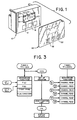
- the modular system is comprised of one or more modules, of the type we have designated "universal monitoring module", the exterior of one such "universal” module being designated by reference numeral 10 in Fig. 1.
- this universal monitoring module 10 remains substantially physically unchanged, regardless of the application in which it is utilized.
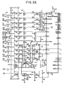
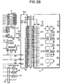
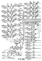
- the module utilizes a substantially fixed circuit configuration, shown in Figs. 2A and 2B or alternatively in Figs.
- modules 8A, 8B and 8C such that only certain programming and memory selection operations need be carried out to, in effect, adapt or customize the module for use with any given machine, vehicle, or the like.
- one or more substantially physically and electrically identical modules such as the module 10 may be programmed and adapted for use with a given machine.
- the module 10 includes one or more operator accessible control means which in the illustrated embodiment comprise pressure-sensitive type switches 12.
- a display panel 14 contains a plurality of visual display elements, including a group of seven-segment alphanumeric characters 16, bar graph displays 18, and various other selectively energizable visual display elements 20. These various visual display elements are suitable for producing visual displays corresponding to a wide variety of functions and conditions. Hence, these displays accommodate those functions and conditions for which a numerical value readout may be required, as well as those for which some analog bar graph type display is appropriate, or for which only some warning indicator or on/off type of display is appropriate.
- the display panel 14 of the illustrated embodiment comprises an LCD (liquid crystal display) panel; however, other types of display elements and arrangements may be utilized without departing from the invention.
- a separate decal or label means 30 is also provided.
- This label 30 may be custom screened, printed or otherwise produced so as to provide labeling for the various display elements to correspond generally to the functions and conditions to be displayed thereby. Accordingly, it will be seen that upon customizing or programming of a given module 10 to monitor a given set of functions and conditions, an appropriate label 30 may be printed or otherwise produced and superimposed upon the face of that module 10.
- the label 30 may further include suitable indicia 32 to be superimposed upon the pressure-sensitive switches 12 to indicate the control operations to be performed by each.
- each monitoring module has a plurality of inputs or input means designated generally by the reference numeral 40.
- These inputs 40 may be coupled to a corresponding plurality of sensors associated with a given machine for receiving sensor signals produced in response to the functions or conditions being monitored by these sensors.
- these input means may include one or more analog inputs or input means, here designated FA1, FA2, FA3 and FA4 for receiving signals from sensors of the type which produce an analog signal corresponding to the value of the monitored function or condition.
- one or more frequency and/or digital inputs may also be provided, here designated by reference characters FQ, Fg, FD1 and FD2, for connection with sensors which produce either a digital signal, or a signal whose frequency varies in accordance with the value of the monitored function or condition.
- Some sensors are of the type which merely switch from one condition to another in response to some associated monitored function reaching a predetermined threshold value or limit. Inputs for such "switching" sensors are here designated as inputs plus 12(A) and plus 12(B).
- One output of the circuit of Fig. 10, designated by reference numeral 42, is for energizing an optional, audible alarm such as a so-called “sonalert” device, if desired, in connection with functions or conditions with which an audible alarm is desired in the event they reach or exceed some threshold value.
- an optional, audible alarm such as a so-called “sonalert” device, if desired, in connection with functions or conditions with which an audible alarm is desired in the event they reach or exceed some threshold value.
- Appropriate input circuits are provided for each of the inputs 40, and are configured for delivering compatible input signals to corresponding inputs of a microprocessor or microcomputer component 46.
- microcomputer 46 comprises a single chip microcomputer of the type generally designated 8032 or 8052.
- the 8052 type microcomputer contains internal of "on-board” memory, whereas selection of the 8032 component requires the addition of a further outboard memory component 50, preferably of the type generally designated D87C64.
- An additional ROM select port 52 permits connection to either a suitable positive voltage or ground, for indicating selection of either the internal or external memory in this regard.
- a to D converter 48 preferably of the type generally designated ADC0833, which feeds a single digital input to a corresponding input port of the microcomputer 46.
- Additional memory capacity is provided connected to the inputs 42, in the form of a non-volatile random access memory (NOVRAM) 54, preferably of the type generally designated NMC9346NE.
- NOVRAM non-volatile random access memory
- the microcomputer component 46 and memory components 50 (if utilized) and 54 together provide processing means responsive to the sensor signals received at the input means 42 for producing display signals corresponding to the associated functions and conditions in accordance with the received sensor signals.
- the microcomputer and memory devices 50 (if utilized) and 54 further comprise or include memory means for storing data and instructions for enabling the processing means to respond to sensor signals from any and all of the sensor means so as to monitor any of the corresponding functions and conditions.
- programming means are provided, including the operator actuatable control switches 32 illustrated and described above with reference to Fig.
- the memory means either on-board the microcomputer 46 or external memory devices 50 and 54
- data and instructions for response to any of a wide variety of particular sensors which may be selected and coupled to the input means 40 for monitoring correspondingly selected functions and conditions of a given vehicle or machine.
- the memory means includes a first memory portion for containing non-changeable operating data.
- operating data would be common to all possible functions and conditions to be monitored, including mathematical calculations and subroutines which may be common to any number of conditions and functions to be monitored and to the types of signals produced by associated sensors.
- the fixed software code or first memory portion may contain data or instructions for in effect recognizing all of the various types of input signals, such as those from switching type sensors and the like, so as to operate the display panel 14 and any audible alarm outputs such as output 42. Since the alarm outputs and the display panel form part of the fixed, nonchangeable module, the corresponding fixed, nonchangeable memory portion may accommodate all of the operating functions for the alarms and displays, regardless of the particular functions and conditions selected to be monitored for a given machine.
- a second memory portion accessible only to factory or service personnel, is provided for entering data corresponding generally to these selected functions and conditions, and more particularly to those types of sensors which may be selected for monitoring this given set of selected functions and conditions. Accordingly, this second memory portion will contain changeable data corresponding to those data and instructions appropriate for monitoring particular types of sensors which may be selected for association with a given machine.
- a third, user accessible memory portion is also preferably provided, which is accessible independently of the first and second memory portions described above.
- This third memory portion is used for receiving and storing data and instructions relating to the particular sensors selected for use with a given machine and their particular characteristics.
- this user-accessible memory portion is further adapted to select either English or metric units for display, as desired by the user.
- Data may also be entered relating to calibration of the processing means for operation with a particular sensor or sensors coupled to the input means, as well as to user-selected alarm limits or the like. That is, the user may wish to select given values with respect to given functions and conditions of the machine which represent threshold values at which an alarm indication is to be produced.
- the user-accessible control means such as the above-described switches 12 are preferably used for the entering of data into the user-accessible memory portion.
- the "operating" or first memory portion mentioned above controls the manner in which the switches may be operated to accomplish user-selection of various data or entry in this fashion.
- the programming means is further operable, and particularly in conjunction with the second memory portion mentioned above, for factory or service selection of the display functions to be associated with each of the visual display elements or portions 16, 18 and/or 20 of the display panel 14. That is, upon having selected certain values or conditions for display, the factory programming may proceed further by assigning the digital display characters 16 to display given values, and assigning other display characters or elements 18, 20 for displaying other values or conditions, as desired. Some of the display elements may also be selectively energized to indicate which function or condition value is currently being displayed by the digital or alphanumeric characters 16, as well.
- the operating program (in the first memory portion) may also provide for user activation of one or more of the user-accessible control members 12 in a given sequence for and enterring of desired data into the third memory portion.
- These data or values may be initially displayed on the alphanumeric characters 16, and then enteredinto the third memory portion when this value corresponds to some desired user-selectable data or alarm limit value, as described above.
- a suitable display driver 56 interface component is also coupled intermediate the microcomputer 46 and display panel 14.
- the display driver 56 comprises a component of the type generally designated PCF2111.
- Fig. 3 forms a functional block diagram or flow chart of the microcomputer operation.
- the user function list is illustrated as an independent block in this program. That is, the user function code is written to operate independently of all "background” functions, and hence user function code may readily be altered to provide alternative lists of user functions.
- the fixed or non-changeable data described above are referred to in Fig. 3 and hereinbelow as "background functions”, and include certain fixed mathematical sub-routines, such as those here referred to as F(g) and F(Q). (These latter fuctions correspond to inputs Fg and FQ mentioned above).
- the microcomputer proceeds to perform various operations or functions in real time at various rates, as represented by TIMER0 (20Hz, 10Hz) and TIMER1 (500Hz), generally in the order indicated in Fig. 3.
- These operations include not only the performing of "background functions" and reading in of data at the inputs 40, but also operating the front panel display portions.
- These operations also accommodate so-called flag directors or preset limits of the monitor unit which will produce appropriate error indications if user operation or attempted operation goes outside of acceptable limits (i. e. , the limits of the fixed operating codes).
- the real time operation under TIMER0 also includes internal memory functions here designated as “set up ordering” and the reading in of user-programmable data and functions, here designated as “user function list” and finally for updating the display (at a 1Hz rate).
- the remaining portion of the diagram under TIMER1 indicates a fixed operations program for operating in real time to read the remaining input channels, preferably in a relatively rapid sequence, so as to in essence simultaneously monitor the signals at all inputs.
- a timer or clock operating at a 500 Hz rate is indicated for this operation.
- the inputs fA1, fA2, etc. here indicated correspond generally to the similarly-designated inputs 40 of Figs. 2A.
- functions F(g) and F(Q) also operate in connection with and accommodate inputs FQ and Fg illustrated and discussed above with reference to Fig. 2A.
- the timer 0 running at substantially 20 hertz initially runs background functions of the operating level programming, and then proceeds to collect data from the Fg and FQ inputs. Thereafter, front panel inputs are read. Finally, flag directors are set in the operating program.
- the 10 hertz clock is derived from the 20 hertz clock and initially does setup and ordering routines, followed by reading the user functions list which includes the functions and operations selected and programmed in by the user, as discussed above. Finally, a derived 1 hertz clock updates the display. Timer 1, running at a 500 hertz rate initially attends to background functions, in similar fashion to the 20 hertz timer, and thereafter serially reads the six "F" channels or inputs.
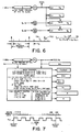
- FIGs. 4, 5 and 6 indicate processing of the FQ and Fg signals. These signals are preferably initially digitally filtered by filters of the form indicated in the lowermost functional block in each of Figs. 4 and 5. The operation of these digital filters is essentially that illustrated and described in U.S. Patent No. 4,633,252.
- the fg signal is what has been termed hereinabove a frequency-type signal, and corresponds to ground speed of a vehicle, as sense by a tachometer, radar ground speed detector or other suitable sensor.
- the fQ signal is also such a frequency signal, which may represent any other of transducer of the type similar to a tachometer or the like, for monitoring a rotational speed of some other machine part, or some similar frequency-related or relatable function.
- the signals are first converted as indicated in Fig. 6 (and described below) to "period" counts or signals Yg and YQ. It will be seen that the processing of these respective signals Yg and YQ is substantially similar.
- the respective signals are essentially summed or "accumulated” with various constants (KQ, KC, weighting factors W and the like) being mathematically factored in to develop corresponding "accumulated" digital signals F2 and F3.
- Fig. 6 illustrates one embodiment of the operation of the microprocessor for initial processing the signals fg and fQ, and particularly the method of obtaining related "period" count signals Yg and YQ from these frequency-related input signals.
- a cycling rate of 20 hertz successive of 50,000 microsecond (50 millisecond) intervals are provided.
- the incoming frequency signal is less than 20 hertz, then the number of 50ms interrupts during each cycle of the incoming frequency are counted.
- These two inversely related count functions are indicated as the Xg, Yg and XQ, YQ functions in the diagram of Fig. 6.
- a 16 bit timer is preloaded at each interrupt to a count of 15,536, such that at a one megahertz count rate, at the end of a 50,000 microsecond period, the counter will have reached a full count of 65, 536 (64K) to thereby fully load the 16 bit counter.
- the 20 hertz timing signal thus results from this operation of the 16 bit timer and one megahertz clock.
- Fig. 3 therefore shows in somewhat diagrammatic form the accumulation of various data from the inputs 42, under the control of clocks running at various frequencies.
- Fig. 7 the effect of a 500 hertz clock on sampling remaining "F" inputs, as previously generally indicated in Fig. 3, is shown in some further detail for a typical one of these inputs or channels. That is, a given "F" input signal, here designated fx is read in at the 500 hertz rate. For those channels in which A to D conversion is used, the digital signal resulting from the A to D converter is read in. These signals can also be accumulated or summed, similar to the F9 and FQ signals, and registers and similar accumulator functions for carrying this out are also shown in Fig. 7. Preferably, these functions are carried out and the resultant values are stored in appropriate registers, whether or not the functions are selected by the user.
- Fig. 7 briefly illustrates the effect of a 500 hertz sample rate on edge detection in a generalized random duty-cycle signal fIN.
- Table No. 1 represents the factory level programming of codes, following identification of some particular functions and conditions of a given machine or vehicle which are to be monitored.
- Table No. 2 consists of a so-called “formula list”, which is preferably part of the ROM level or non-changeable operating level programming of the apparatus of the invention.
- the "user function list” of Table No. 3 represents user programmable functions in the NOVRAM, based upon a pre-identified machine and list of functions and conditions to be monitored.
- Figs. 8A, 8B and 8C taken together, form a schematic circuit diagram of an alternate form of circuit in accordance wtih the invention.
- the circuit of Fig. 8 is substantially similar to the circuit of Fig. 2, but represents a somewhat larger capacity arrangement, having some additional inputs and somewhat larger processing capabilities than the embodiment of Fig. 2. In all other respects, the circuit of Fig. 8 operates substantially similarly to the circuits already described hereinabove.
Landscapes
- Physics & Mathematics (AREA)
- General Physics & Mathematics (AREA)
- Testing And Monitoring For Control Systems (AREA)
Applications Claiming Priority (4)
| Application Number | Priority Date | Filing Date | Title |
|---|---|---|---|
| US15478688A | 1988-02-10 | 1988-02-10 | |
| US154786 | 1988-02-10 | ||
| US238975 | 1988-08-23 | ||
| US07/238,975 US4924418A (en) | 1988-02-10 | 1988-08-23 | Universal monitor |
Publications (1)
| Publication Number | Publication Date |
|---|---|
| EP0330347A1 true EP0330347A1 (de) | 1989-08-30 |
Family
ID=26851779
Family Applications (1)
| Application Number | Title | Priority Date | Filing Date |
|---|---|---|---|
| EP89301299A Withdrawn EP0330347A1 (de) | 1988-02-10 | 1989-02-10 | Universelle Überwachungsvorrichtung |
Country Status (4)
| Country | Link |
|---|---|
| US (1) | US4924418A (de) |
| EP (1) | EP0330347A1 (de) |
| CA (1) | CA1304501C (de) |
| DK (1) | DK64689A (de) |
Cited By (4)
| Publication number | Priority date | Publication date | Assignee | Title |
|---|---|---|---|---|
| EP0827585A1 (de) * | 1995-04-18 | 1998-03-11 | Curtis Instruments, Inc. | Kompaktes preiswertes halbleiterinstrument |
| GB2349020A (en) * | 1999-04-17 | 2000-10-18 | Interface Inf Syst Ltd | Monitoring condition of a machine |
| EP1297733A1 (de) * | 2001-09-27 | 2003-04-02 | CLAAS Selbstfahrende Erntemaschinen GmbH | Verfahren und Vorrichtung zur Ermittlung einer Erntemaschineneinstellung |
| WO2007131729A1 (de) * | 2006-05-12 | 2007-11-22 | Ksb Aktiengesellschaft | Einrichtung zur messwertübertragung |
Families Citing this family (130)
| Publication number | Priority date | Publication date | Assignee | Title |
|---|---|---|---|---|
| FR2641636A1 (fr) * | 1989-01-11 | 1990-07-13 | Mast Air Entreprise | Dispositif de controle de l'utilisation d'un engin de locomotion |
| US5289381A (en) * | 1989-12-04 | 1994-02-22 | Maschinenfabrik Rieter Ag | Method and apparatus for continuously determining the fineness of fibers in slivers |
| US5335186A (en) * | 1990-03-30 | 1994-08-02 | Texas Instruments Incorporated | Intelligent programmable sensing |
| US5249138A (en) * | 1991-01-07 | 1993-09-28 | Computational Systems, Inc. | Analog signal preprocessor |
| US5446390A (en) * | 1992-01-15 | 1995-08-29 | Sgs-Thomson Microelectronics, Inc. | Method and apparatus for monitoring and displaying sequentially operating conditions of a plurality of devices |
| US5323721A (en) * | 1992-03-20 | 1994-06-28 | Micro-Trak Systems, Inc. | Planter monitor system |
| WO1993025412A1 (en) * | 1992-06-10 | 1993-12-23 | Ford Motor Company Limited | A communication system for motor vehicles |
| JPH06213061A (ja) * | 1992-09-16 | 1994-08-02 | Caterpillar Inc | 入力を選択的に監視する方法及び装置 |
| JP3533685B2 (ja) * | 1993-10-04 | 2004-05-31 | セイコーエプソン株式会社 | 車両用画像データ演算装置及びその制御方法 |
| DE4341834C1 (de) * | 1993-12-08 | 1995-04-20 | Claas Ohg | Landmaschine, insbesondere Mähdrescher, mit Multiprozessor-Leitvorrichtung |
| US5475614A (en) * | 1994-01-13 | 1995-12-12 | Micro-Trak Systems, Inc. | Method and apparatus for controlling a variable fluid delivery system |
| US5574657A (en) * | 1994-02-08 | 1996-11-12 | Micro-Trak Systems, Inc. | Electronic rate meter controller and method |
| US5648898A (en) * | 1994-12-19 | 1997-07-15 | Caterpillar Inc. | Method for programming a vehicle monitoring and control system |
| CA2141092C (en) * | 1995-01-25 | 1999-01-05 | James F. White | Communication between components of a machine |
| US5598794A (en) * | 1995-02-13 | 1997-02-04 | Fluid Power Industries, Inc. | High accuracy automatically controlled variable linear seed spacing planting apparatus |
| US5724242A (en) * | 1995-03-21 | 1998-03-03 | Caterpillar Inc. | Method for producing production control software for a natural gas engine controller |
| US6269300B1 (en) | 1995-03-29 | 2001-07-31 | Caterpillar Inc. | Method for producing production control software for a natural gas or diesel engine controller |
| US5621666A (en) * | 1995-04-20 | 1997-04-15 | Dynavisions, Inc. | Planter monitor |
| US5839094A (en) * | 1995-06-30 | 1998-11-17 | Ada Technologies, Inc. | Portable data collection device with self identifying probe |
| US7254518B2 (en) * | 1996-03-28 | 2007-08-07 | Rosemount Inc. | Pressure transmitter with diagnostics |
| US6017143A (en) | 1996-03-28 | 2000-01-25 | Rosemount Inc. | Device in a process system for detecting events |
| US7630861B2 (en) | 1996-03-28 | 2009-12-08 | Rosemount Inc. | Dedicated process diagnostic device |
| US7623932B2 (en) | 1996-03-28 | 2009-11-24 | Fisher-Rosemount Systems, Inc. | Rule set for root cause diagnostics |
| US6539267B1 (en) | 1996-03-28 | 2003-03-25 | Rosemount Inc. | Device in a process system for determining statistical parameter |
| US8290721B2 (en) | 1996-03-28 | 2012-10-16 | Rosemount Inc. | Flow measurement diagnostics |
| US6654697B1 (en) | 1996-03-28 | 2003-11-25 | Rosemount Inc. | Flow measurement with diagnostics |
| US6907383B2 (en) | 1996-03-28 | 2005-06-14 | Rosemount Inc. | Flow diagnostic system |
| US7085610B2 (en) | 1996-03-28 | 2006-08-01 | Fisher-Rosemount Systems, Inc. | Root cause diagnostics |
| US7949495B2 (en) | 1996-03-28 | 2011-05-24 | Rosemount, Inc. | Process variable transmitter with diagnostics |
| US5897600A (en) * | 1996-08-22 | 1999-04-27 | Elmore; Thomas R. | Universal modular control system for mobile material distribution apparatus |
| US5884205A (en) * | 1996-08-22 | 1999-03-16 | Dickey-John Corporation | Boom configuration monitoring and control system for mobile material distribution apparatus |
| US5801948A (en) * | 1996-08-22 | 1998-09-01 | Dickey-John Corporation | Universal control system with alarm history tracking for mobile material distribution apparatus |
| US6519546B1 (en) | 1996-11-07 | 2003-02-11 | Rosemount Inc. | Auto correcting temperature transmitter with resistance based sensor |
| US6754601B1 (en) | 1996-11-07 | 2004-06-22 | Rosemount Inc. | Diagnostics for resistive elements of process devices |
| US6449574B1 (en) | 1996-11-07 | 2002-09-10 | Micro Motion, Inc. | Resistance based process control device diagnostics |
| US6434504B1 (en) | 1996-11-07 | 2002-08-13 | Rosemount Inc. | Resistance based process control device diagnostics |
| US6601005B1 (en) | 1996-11-07 | 2003-07-29 | Rosemount Inc. | Process device diagnostics using process variable sensor signal |
| US5956663A (en) * | 1996-11-07 | 1999-09-21 | Rosemount, Inc. | Signal processing technique which separates signal components in a sensor for sensor diagnostics |
| DE69714606T9 (de) * | 1996-12-31 | 2004-09-09 | Rosemount Inc., Eden Prairie | Vorrichtung zur überprüfung eines von einer anlage kommenden steuersignals in einer prozesssteuerung |
| US5911362A (en) * | 1997-02-26 | 1999-06-15 | Dickey-John Corporation | Control system for a mobile material distribution device |
| CA2306767C (en) | 1997-10-13 | 2007-05-01 | Rosemount Inc. | Communication technique for field devices in industrial processes |
| US6339373B1 (en) | 1998-05-01 | 2002-01-15 | Dale A. Zeskind | Sensor device providing indication of device health |
| US6611775B1 (en) | 1998-12-10 | 2003-08-26 | Rosemount Inc. | Electrode leakage diagnostics in a magnetic flow meter |
| US6615149B1 (en) | 1998-12-10 | 2003-09-02 | Rosemount Inc. | Spectral diagnostics in a magnetic flow meter |
| US7562135B2 (en) * | 2000-05-23 | 2009-07-14 | Fisher-Rosemount Systems, Inc. | Enhanced fieldbus device alerts in a process control system |
| US7206646B2 (en) * | 1999-02-22 | 2007-04-17 | Fisher-Rosemount Systems, Inc. | Method and apparatus for performing a function in a plant using process performance monitoring with process equipment monitoring and control |
| US6298454B1 (en) | 1999-02-22 | 2001-10-02 | Fisher-Rosemount Systems, Inc. | Diagnostics in a process control system |
| US8044793B2 (en) | 2001-03-01 | 2011-10-25 | Fisher-Rosemount Systems, Inc. | Integrated device alerts in a process control system |
| US6633782B1 (en) | 1999-02-22 | 2003-10-14 | Fisher-Rosemount Systems, Inc. | Diagnostic expert in a process control system |
| US7346404B2 (en) * | 2001-03-01 | 2008-03-18 | Fisher-Rosemount Systems, Inc. | Data sharing in a process plant |
| US6356191B1 (en) | 1999-06-17 | 2002-03-12 | Rosemount Inc. | Error compensation for a process fluid temperature transmitter |
| US7010459B2 (en) * | 1999-06-25 | 2006-03-07 | Rosemount Inc. | Process device diagnostics using process variable sensor signal |
| KR100302384B1 (ko) * | 1999-07-01 | 2001-09-22 | 김오영 | 자동차 전기장치의 디지털 통합 제어장치 및 방법 |
| JP4824234B2 (ja) | 1999-07-01 | 2011-11-30 | ローズマウント インコーポレイテッド | 2線式温度送信機およびプロセス温度測定方法 |
| US6505517B1 (en) | 1999-07-23 | 2003-01-14 | Rosemount Inc. | High accuracy signal processing for magnetic flowmeter |
| US6701274B1 (en) | 1999-08-27 | 2004-03-02 | Rosemount Inc. | Prediction of error magnitude in a pressure transmitter |
| US6556145B1 (en) | 1999-09-24 | 2003-04-29 | Rosemount Inc. | Two-wire fluid temperature transmitter with thermocouple diagnostics |
| US6957172B2 (en) * | 2000-03-09 | 2005-10-18 | Smartsignal Corporation | Complex signal decomposition and modeling |
| US6781923B1 (en) * | 2000-09-13 | 2004-08-24 | Timex Group B.V. | Method and apparatus for tracking usage of a multi-functional electronic device |
| US6735484B1 (en) | 2000-09-20 | 2004-05-11 | Fargo Electronics, Inc. | Printer with a process diagnostics system for detecting events |
| US7720727B2 (en) | 2001-03-01 | 2010-05-18 | Fisher-Rosemount Systems, Inc. | Economic calculations in process control system |
| US8073967B2 (en) | 2002-04-15 | 2011-12-06 | Fisher-Rosemount Systems, Inc. | Web services-based communications for use with process control systems |
| EP1364262B1 (de) | 2001-03-01 | 2005-11-02 | Fisher-Rosemount Systems, Inc. | Erzeugung und anzeige von verzeichnissen in einer prozessanlage |
| US6970003B2 (en) | 2001-03-05 | 2005-11-29 | Rosemount Inc. | Electronics board life prediction of microprocessor-based transmitters |
| US6629059B2 (en) | 2001-05-14 | 2003-09-30 | Fisher-Rosemount Systems, Inc. | Hand held diagnostic and communication device with automatic bus detection |
| US6772036B2 (en) | 2001-08-30 | 2004-08-03 | Fisher-Rosemount Systems, Inc. | Control system using process model |
| US6642838B1 (en) | 2002-10-31 | 2003-11-04 | Charles A. Barnas | Safety system for automobiles |
| US7114388B1 (en) | 2003-04-21 | 2006-10-03 | Ada Technologies, Inc. | Geographically distributed environmental sensor system |
| WO2005010522A2 (en) | 2003-07-18 | 2005-02-03 | Rosemount Inc. | Process diagnostics |
| US7018800B2 (en) | 2003-08-07 | 2006-03-28 | Rosemount Inc. | Process device with quiescent current diagnostics |
| US7627441B2 (en) | 2003-09-30 | 2009-12-01 | Rosemount Inc. | Process device with vibration based diagnostics |
| US7274907B1 (en) | 2003-12-19 | 2007-09-25 | Unites States Of America As Represented By The Administrator Of The National Aeronautics And Space Administration | Wireless instrumentation system and power management scheme therefore |
| US7523667B2 (en) | 2003-12-23 | 2009-04-28 | Rosemount Inc. | Diagnostics of impulse piping in an industrial process |
| US6920799B1 (en) | 2004-04-15 | 2005-07-26 | Rosemount Inc. | Magnetic flow meter with reference electrode |
| US7046180B2 (en) | 2004-04-21 | 2006-05-16 | Rosemount Inc. | Analog-to-digital converter with range error detection |
| US7412842B2 (en) | 2004-04-27 | 2008-08-19 | Emerson Climate Technologies, Inc. | Compressor diagnostic and protection system |
| US7275377B2 (en) | 2004-08-11 | 2007-10-02 | Lawrence Kates | Method and apparatus for monitoring refrigerant-cycle systems |
| US9201420B2 (en) | 2005-04-08 | 2015-12-01 | Rosemount, Inc. | Method and apparatus for performing a function in a process plant using monitoring data with criticality evaluation data |
| US8005647B2 (en) | 2005-04-08 | 2011-08-23 | Rosemount, Inc. | Method and apparatus for monitoring and performing corrective measures in a process plant using monitoring data with corrective measures data |
| US8112565B2 (en) * | 2005-06-08 | 2012-02-07 | Fisher-Rosemount Systems, Inc. | Multi-protocol field device interface with automatic bus detection |
| US7272531B2 (en) | 2005-09-20 | 2007-09-18 | Fisher-Rosemount Systems, Inc. | Aggregation of asset use indices within a process plant |
| US20070068225A1 (en) | 2005-09-29 | 2007-03-29 | Brown Gregory C | Leak detector for process valve |
| US8590325B2 (en) | 2006-07-19 | 2013-11-26 | Emerson Climate Technologies, Inc. | Protection and diagnostic module for a refrigeration system |
| US20080216494A1 (en) | 2006-09-07 | 2008-09-11 | Pham Hung M | Compressor data module |
| US10064784B2 (en) | 2006-09-14 | 2018-09-04 | Martin B. Rawls-Meehan | System and method of an adjustable bed with a vibration motor |
| US10864137B2 (en) | 2006-09-14 | 2020-12-15 | Ascion, Llc | System and method of an adjustable bed with a vibration motor |
| US8909378B2 (en) * | 2006-09-14 | 2014-12-09 | Martin B Rawls-Meehan | Adjustable bed position control |
| US8926535B2 (en) | 2006-09-14 | 2015-01-06 | Martin B. Rawls-Meehan | Adjustable bed position control |
| US7465280B2 (en) | 2006-09-14 | 2008-12-16 | Rawls-Meehan Martin B | Methods and systems of mounting a vibration motor to an adjustable bed |
| US8275577B2 (en) | 2006-09-19 | 2012-09-25 | Smartsignal Corporation | Kernel-based method for detecting boiler tube leaks |
| US8774204B2 (en) * | 2006-09-25 | 2014-07-08 | Fisher-Rosemount Systems, Inc. | Handheld field maintenance bus monitor |
| US7953501B2 (en) | 2006-09-25 | 2011-05-31 | Fisher-Rosemount Systems, Inc. | Industrial process control loop monitor |
| US8788070B2 (en) * | 2006-09-26 | 2014-07-22 | Rosemount Inc. | Automatic field device service adviser |
| EP2074385B2 (de) | 2006-09-29 | 2022-07-06 | Rosemount Inc. | Magnetischer flussmesser mit verifikationsfunktion |
| US7321846B1 (en) | 2006-10-05 | 2008-01-22 | Rosemount Inc. | Two-wire process control loop diagnostics |
| US8311774B2 (en) | 2006-12-15 | 2012-11-13 | Smartsignal Corporation | Robust distance measures for on-line monitoring |
| US8275313B1 (en) | 2007-01-15 | 2012-09-25 | Advanced Distributed Sensor Systems | Long range, low power, mesh networking without concurrent timing |
| US20090037142A1 (en) | 2007-07-30 | 2009-02-05 | Lawrence Kates | Portable method and apparatus for monitoring refrigerant-cycle systems |
| US8898036B2 (en) | 2007-08-06 | 2014-11-25 | Rosemount Inc. | Process variable transmitter with acceleration sensor |
| US8301676B2 (en) | 2007-08-23 | 2012-10-30 | Fisher-Rosemount Systems, Inc. | Field device with capability of calculating digital filter coefficients |
| US7702401B2 (en) | 2007-09-05 | 2010-04-20 | Fisher-Rosemount Systems, Inc. | System for preserving and displaying process control data associated with an abnormal situation |
| US7590511B2 (en) | 2007-09-25 | 2009-09-15 | Rosemount Inc. | Field device for digital process control loop diagnostics |
| US8055479B2 (en) | 2007-10-10 | 2011-11-08 | Fisher-Rosemount Systems, Inc. | Simplified algorithm for abnormal situation prevention in load following applications including plugged line diagnostics in a dynamic process |
| US9140728B2 (en) | 2007-11-02 | 2015-09-22 | Emerson Climate Technologies, Inc. | Compressor sensor module |
| US8126605B2 (en) * | 2007-12-05 | 2012-02-28 | Toyota Motor Engineering & Manufacturing North America, Inc. | Computing platform for multiple intelligent transportation systems in an automotive vehicle |
| US7921734B2 (en) * | 2009-05-12 | 2011-04-12 | Rosemount Inc. | System to detect poor process ground connections |
| WO2012061406A2 (en) | 2010-11-01 | 2012-05-10 | Rawls-Meehan Martin B | Adjustable bed controls |
| CA2828740C (en) | 2011-02-28 | 2016-07-05 | Emerson Electric Co. | Residential solutions hvac monitoring and diagnosis |
| US9207670B2 (en) | 2011-03-21 | 2015-12-08 | Rosemount Inc. | Degrading sensor detection implemented within a transmitter |
| US9927788B2 (en) | 2011-05-19 | 2018-03-27 | Fisher-Rosemount Systems, Inc. | Software lockout coordination between a process control system and an asset management system |
| US8620853B2 (en) | 2011-07-19 | 2013-12-31 | Smartsignal Corporation | Monitoring method using kernel regression modeling with pattern sequences |
| US9256224B2 (en) | 2011-07-19 | 2016-02-09 | GE Intelligent Platforms, Inc | Method of sequential kernel regression modeling for forecasting and prognostics |
| US9250625B2 (en) | 2011-07-19 | 2016-02-02 | Ge Intelligent Platforms, Inc. | System of sequential kernel regression modeling for forecasting and prognostics |
| US8660980B2 (en) | 2011-07-19 | 2014-02-25 | Smartsignal Corporation | Monitoring system using kernel regression modeling with pattern sequences |
| US8799201B2 (en) | 2011-07-25 | 2014-08-05 | Toyota Motor Engineering & Manufacturing North America, Inc. | Method and system for tracking objects |
| WO2013101747A1 (en) * | 2011-12-29 | 2013-07-04 | General Electric Company | Apparatus and method for controlling an internal combustion engine |
| US10495014B2 (en) | 2011-12-29 | 2019-12-03 | Ge Global Sourcing Llc | Systems and methods for displaying test details of an engine control test |
| US8964338B2 (en) | 2012-01-11 | 2015-02-24 | Emerson Climate Technologies, Inc. | System and method for compressor motor protection |
| CA2865697C (en) | 2012-02-28 | 2018-01-09 | Jeffrey N. Arensmeier | Hvac system remote monitoring and diagnosis |
| US9052240B2 (en) | 2012-06-29 | 2015-06-09 | Rosemount Inc. | Industrial process temperature transmitter with sensor stress diagnostics |
| US9310439B2 (en) | 2012-09-25 | 2016-04-12 | Emerson Climate Technologies, Inc. | Compressor having a control and diagnostic module |
| US9207129B2 (en) | 2012-09-27 | 2015-12-08 | Rosemount Inc. | Process variable transmitter with EMF detection and correction |
| US9602122B2 (en) | 2012-09-28 | 2017-03-21 | Rosemount Inc. | Process variable measurement noise diagnostic |
| US9551504B2 (en) | 2013-03-15 | 2017-01-24 | Emerson Electric Co. | HVAC system remote monitoring and diagnosis |
| US9803902B2 (en) | 2013-03-15 | 2017-10-31 | Emerson Climate Technologies, Inc. | System for refrigerant charge verification using two condenser coil temperatures |
| US9638436B2 (en) | 2013-03-15 | 2017-05-02 | Emerson Electric Co. | HVAC system remote monitoring and diagnosis |
| EP2981772B1 (de) | 2013-04-05 | 2022-01-12 | Emerson Climate Technologies, Inc. | Wärmepumpensystem mit kühlmittelladungsdiagnostik |
| US10139267B2 (en) * | 2014-01-09 | 2018-11-27 | General Electric Company | Systems and methods for storage and analysis of periodic waveform data |
| USD800739S1 (en) | 2016-02-16 | 2017-10-24 | General Electric Company | Display screen with graphical user interface for displaying test details of an engine control test |
| US20180163991A1 (en) * | 2016-12-13 | 2018-06-14 | Haier Us Appliance Solutions, Inc. | Water Heater Appliance |
Citations (8)
| Publication number | Priority date | Publication date | Assignee | Title |
|---|---|---|---|---|
| US4296409A (en) * | 1979-03-12 | 1981-10-20 | Dickey-John Corporation | Combine performance monitor |
| WO1982002785A1 (en) * | 1981-02-13 | 1982-08-19 | Dyrdak Waldemar | Computer system for vehicles |
| EP0094090A1 (de) * | 1982-05-12 | 1983-11-16 | Hitachi, Ltd. | Anzeigeeinrichtung für Fahrzeuge |
| WO1984004413A1 (en) * | 1983-05-05 | 1984-11-08 | Finommech Elekt Mueszer Szoeve | Installation for measuring given parameters in any process for an eventual intervention, and for the storage and processing of data |
| US4551801A (en) * | 1983-02-07 | 1985-11-05 | Dickey-John Corporation | Modular vehicular monitoring system |
| EP0163775A1 (de) * | 1984-05-25 | 1985-12-11 | Robert Bosch Gmbh | Steuervorrichtung für Funktionen im Kraftfahrzeug |
| WO1986006190A1 (en) * | 1985-04-12 | 1986-10-23 | Massey-Ferguson Services N.V. | Vehicle performance monitoring apparatus |
| EP0308154A2 (de) * | 1987-09-15 | 1989-03-22 | Dickey-John Corporation | Universalregler für Verteilvorrichtung von Material |
Family Cites Families (11)
| Publication number | Priority date | Publication date | Assignee | Title |
|---|---|---|---|---|
| US4052003A (en) * | 1976-08-06 | 1977-10-04 | Dickey-John Corporation | Liquid spreader control system |
| US4258421A (en) * | 1978-02-27 | 1981-03-24 | Rockwell International Corporation | Vehicle monitoring and recording system |
| US4376298A (en) * | 1980-08-06 | 1983-03-08 | Dickey-John Corporation | Combine data center |
| US4432064A (en) * | 1980-10-27 | 1984-02-14 | Halliburton Company | Apparatus for monitoring a plurality of operations |
| US4404641A (en) * | 1981-02-17 | 1983-09-13 | Dierckx Equipment Corporation | Maintenance monitor |
| US4392611A (en) * | 1981-05-15 | 1983-07-12 | Dickey-John Corporation | Sprayer control system |
| US4419654A (en) * | 1981-07-17 | 1983-12-06 | Dickey-John Corporation | Tractor data center |
| DK557884A (da) * | 1983-11-25 | 1985-05-26 | Mars Inc | Automatisk testudstyr |
| US4613939A (en) * | 1984-08-08 | 1986-09-23 | Caterpillar Industrial Inc. | Programmable service reminder apparatus and method |
| US4757463A (en) * | 1986-06-02 | 1988-07-12 | International Business Machines Corp. | Fault isolation for vehicle using a multifunction test probe |
| US4764727A (en) * | 1986-10-14 | 1988-08-16 | Mcconchie Sr Noel P | Circuit continuity and voltage tester |
-
1988
- 1988-08-23 US US07/238,975 patent/US4924418A/en not_active Expired - Lifetime
-
1989
- 1989-02-06 CA CA000590202A patent/CA1304501C/en not_active Expired - Lifetime
- 1989-02-10 DK DK064689A patent/DK64689A/da not_active Application Discontinuation
- 1989-02-10 EP EP89301299A patent/EP0330347A1/de not_active Withdrawn
Patent Citations (8)
| Publication number | Priority date | Publication date | Assignee | Title |
|---|---|---|---|---|
| US4296409A (en) * | 1979-03-12 | 1981-10-20 | Dickey-John Corporation | Combine performance monitor |
| WO1982002785A1 (en) * | 1981-02-13 | 1982-08-19 | Dyrdak Waldemar | Computer system for vehicles |
| EP0094090A1 (de) * | 1982-05-12 | 1983-11-16 | Hitachi, Ltd. | Anzeigeeinrichtung für Fahrzeuge |
| US4551801A (en) * | 1983-02-07 | 1985-11-05 | Dickey-John Corporation | Modular vehicular monitoring system |
| WO1984004413A1 (en) * | 1983-05-05 | 1984-11-08 | Finommech Elekt Mueszer Szoeve | Installation for measuring given parameters in any process for an eventual intervention, and for the storage and processing of data |
| EP0163775A1 (de) * | 1984-05-25 | 1985-12-11 | Robert Bosch Gmbh | Steuervorrichtung für Funktionen im Kraftfahrzeug |
| WO1986006190A1 (en) * | 1985-04-12 | 1986-10-23 | Massey-Ferguson Services N.V. | Vehicle performance monitoring apparatus |
| EP0308154A2 (de) * | 1987-09-15 | 1989-03-22 | Dickey-John Corporation | Universalregler für Verteilvorrichtung von Material |
Cited By (7)
| Publication number | Priority date | Publication date | Assignee | Title |
|---|---|---|---|---|
| EP0827585A1 (de) * | 1995-04-18 | 1998-03-11 | Curtis Instruments, Inc. | Kompaktes preiswertes halbleiterinstrument |
| EP0827585A4 (de) * | 1995-04-18 | 1999-05-12 | Curtis Instr | Kompaktes preiswertes halbleiterinstrument |
| US6202039B1 (en) * | 1995-04-18 | 2001-03-13 | Curtis Instruments, Inc. | Compact, low-cost semiconductor device for receiving arbitrary input parameters and driving selected display devices, and methods |
| GB2349020A (en) * | 1999-04-17 | 2000-10-18 | Interface Inf Syst Ltd | Monitoring condition of a machine |
| EP1297733A1 (de) * | 2001-09-27 | 2003-04-02 | CLAAS Selbstfahrende Erntemaschinen GmbH | Verfahren und Vorrichtung zur Ermittlung einer Erntemaschineneinstellung |
| WO2007131729A1 (de) * | 2006-05-12 | 2007-11-22 | Ksb Aktiengesellschaft | Einrichtung zur messwertübertragung |
| US7991586B2 (en) | 2006-05-12 | 2011-08-02 | Ksb Aktiengesellschaft | Device for transmitting measured values |
Also Published As
| Publication number | Publication date |
|---|---|
| CA1304501C (en) | 1992-06-30 |
| US4924418A (en) | 1990-05-08 |
| DK64689D0 (da) | 1989-02-10 |
| DK64689A (da) | 1989-08-11 |
Similar Documents
| Publication | Publication Date | Title |
|---|---|---|
| EP0330347A1 (de) | Universelle Überwachungsvorrichtung | |
| US4551801A (en) | Modular vehicular monitoring system | |
| EP0547052B1 (de) | Adaptive anzeige für fahrzeuge | |
| DE10015009B4 (de) | Flurförderzeug mit einem Anzeige-, Steuerungs- und Überwachungssystem | |
| JPS5790106A (en) | Driving indicator for automobile | |
| DE3608658C2 (de) | ||
| EP0074498B1 (de) | Verfahren und Vorrichtung zum Eichen von Messfühlern | |
| US5432497A (en) | Electronically programmable gauge | |
| EP0354563B1 (de) | Vorrichtung zur Änderung der Fahreigenschaften eines Fahrzeugs | |
| EP0592166A2 (de) | Fahrtschreiber | |
| US5369740A (en) | Versatile programmable electronic controller | |
| EP0094090B1 (de) | Anzeigeeinrichtung für Fahrzeuge | |
| DE102011055886A1 (de) | Reifenzustandsüberwachungssystem und Montagepositionsermittlungsverfahren | |
| EP0416171A2 (de) | Verfahren zur Bildschirmdarstellung in elektrischen Fahrzeugen | |
| EP0388523A2 (de) | Anordnung zum Anzeigen der Restladung eines Akkumulators | |
| WO1994006100A1 (de) | Verfahren und vorrichtung zum bestimmen, registrieren und fallweisen auswerten von betriebs- und/oder fahrdaten eines fahrzeuges | |
| US4068307A (en) | Mile post location display system | |
| EP0529523A1 (de) | Ansteuerung für mehrere Anzeigegeräte | |
| US20020080047A1 (en) | Driving practice display device of surrounding vehicles | |
| EP0262989B1 (de) | Verfahrenssteuerungsanlage zur Anwendung in widrigen Umgebungen | |
| EP0635135B1 (de) | Verfahren zur überwachung von drehzahlfühlern | |
| GB2152673A (en) | Temperature monitoring system | |
| US4857889A (en) | Liquid-crystal indicator control system | |
| GB2133556A (en) | Planter population monitor | |
| EP1512563B1 (de) | Anzeigevorrichtung |
Legal Events
| Date | Code | Title | Description |
|---|---|---|---|
| PUAI | Public reference made under article 153(3) epc to a published international application that has entered the european phase |
Free format text: ORIGINAL CODE: 0009012 |
|
| AK | Designated contracting states |
Kind code of ref document: A1 Designated state(s): DE FR GB IT |
|
| 17P | Request for examination filed |
Effective date: 19900227 |
|
| 17Q | First examination report despatched |
Effective date: 19920220 |
|
| STAA | Information on the status of an ep patent application or granted ep patent |
Free format text: STATUS: THE APPLICATION IS DEEMED TO BE WITHDRAWN |
|
| 18D | Application deemed to be withdrawn |
Effective date: 19920902 |