EP0330101A2 - Device for analysis of articulation between upper and lower jaws - Google Patents
Device for analysis of articulation between upper and lower jaws Download PDFInfo
- Publication number
- EP0330101A2 EP0330101A2 EP89102843A EP89102843A EP0330101A2 EP 0330101 A2 EP0330101 A2 EP 0330101A2 EP 89102843 A EP89102843 A EP 89102843A EP 89102843 A EP89102843 A EP 89102843A EP 0330101 A2 EP0330101 A2 EP 0330101A2
- Authority
- EP
- European Patent Office
- Prior art keywords
- lower jaw
- plate
- jaw
- upper jaw
- movement
- Prior art date
- Legal status (The legal status is an assumption and is not a legal conclusion. Google has not performed a legal analysis and makes no representation as to the accuracy of the status listed.)
- Granted
Links
- 230000005855 radiation Effects 0.000 claims abstract description 18
- 238000001514 detection method Methods 0.000 claims abstract description 12
- 238000004519 manufacturing process Methods 0.000 description 3
- 230000001055 chewing effect Effects 0.000 description 2
- 238000000034 method Methods 0.000 description 2
- 239000004020 conductor Substances 0.000 description 1
- 210000004513 dentition Anatomy 0.000 description 1
- 238000006073 displacement reaction Methods 0.000 description 1
- 238000011156 evaluation Methods 0.000 description 1
- 239000000463 material Substances 0.000 description 1
- 238000005259 measurement Methods 0.000 description 1
- 230000001502 supplementing effect Effects 0.000 description 1
- 210000001738 temporomandibular joint Anatomy 0.000 description 1
- 230000036346 tooth eruption Effects 0.000 description 1
Images
Classifications
-
- A—HUMAN NECESSITIES
- A61—MEDICAL OR VETERINARY SCIENCE; HYGIENE
- A61C—DENTISTRY; APPARATUS OR METHODS FOR ORAL OR DENTAL HYGIENE
- A61C19/00—Dental auxiliary appliances
- A61C19/04—Measuring instruments specially adapted for dentistry
- A61C19/045—Measuring instruments specially adapted for dentistry for recording mandibular movement, e.g. face bows
Definitions
- the invention relates to a device for analyzing the articulation movement between the upper jaw and lower jaw, in particular with contact of the teeth of the upper jaw and lower jaw.
- a measuring device is used to register the articulation movement, which is attached to the lower jaw and has a bracket projecting towards the lower jaw joints (condyles).
- the so-called condylar pole is scanned and a writing tip of the facebow is aligned with this point.
- a registration sheet is placed under the tip of the pen, on which the movement of the condyles is recorded while the patient is chewing.
- the consistent measuring principle consists in determining the movement of the lower jaw in order to simulate the individual movement of the lower jaw to the upper jaw as precisely as possible in the manufacture of the dental prosthesis in the dental laboratory.
- Further devices have become known for this purpose, e.g. B. the Stereo-Gnathograph-V from Dental-Elektronik KG in 8480 Weiden.
- the mechanical recording system has been replaced by a non-contact motion detection system that has three infrared transmitters and three infrared receivers in the ear area, between which a suitably designed plate can be moved, which is connected to the facebow.
- the movement at the condylar end of the facebow is detected by the non-contact movement detection system and can be recorded electronically.
- nothing has changed in the actual measuring principle.
- the invention has for its object to provide a device of the type mentioned in such a way that an accurate and reliable determination of the movement of the lower jaw relative to the upper jaw is possible in that the articulation movement is not disturbed by parts of the device attached to the lower jaw outside the mouth area.
- This object is achieved according to the invention in a device of the type mentioned at the outset by two plates inserted into the upper jaw and lower jaw, which have a transmitter arrangement with a plurality of radiation sources and a receiver arrangement for the detection of impingement points of the emitted beams.
- a sideways movement of the lower jaw parallel to the upper jaw creates a scratch mark in the form of an arrow on the lower jaw plate, which, particularly at its outer ends, provides information about the function of the temporomandibular joint in the lateral movement of the lower jaw and the detection of the central relation of the jaws based on the position of the jaw Arrowheads allowed.
- the analysis of a chewing movement in which the teeth come into contact with one another is neither provided nor possible.
- the radiation sources and the receiver arrangement are arranged on the same plate and the second plate only functions as a reflector for the emitted beams.
- the embodiment is preferred in which a plate contains the transmitter arrangement (transmitter plate) and the other plate has the receiver arrangement (receiver plate).
- the transmitter arrangement will generally require slightly more height than the receiver arrangement, so that it is expedient to insert the plate with the transmitter arrangement into the jaw, where there is the most space due to the individual anatomical situation.
- two radiation sources which are parallel to one another and at least one radiation source which is at an angle thereto are advantageously used.
- the distance between the point of incidence of the inclined radiation source and one of the radiation sources arranged in parallel varies with the distance between the plates.
- the impingement points of the two radiation sources which are parallel to one another enable the detection of a plane-parallel displacement of the plates relative to one another and a relative tilting movement which leads to a change in the distance between the impingement points of these two radiation sources.
- the radiation sources which are parallel to one another are preferably oriented such that they are substantially perpendicular to the receiver plate during the contact of the teeth of the upper jaw and lower jaw.
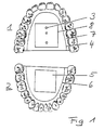
- FIG. 1 shows an upper jaw 1 and a lower jaw 2.
- a first plate 4 carrying radiation sources 3 is inserted, which functions as a transmitter plate, while in the lower jaw 2 a plate 6 carrying a sensor surface 5 is inserted.
- Both plates 4, 6 are fitted with a suitable compensating material 7.
- the first plate 4 (transmitter plate) holds a carrier plate 8 which carries three light sources 3 which act as radiation sources.
- the second plate 6 (receiver plate) inserted in the lower jaw carries a sensor surface 5, which enables the detection of points of incidence of the light beams with the coordinates on the sensor surface 5.
- the sensor surface 5 is scanned in the form of a line, with a defined electrical value being assigned to each point of impact.
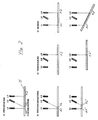
- Figure 2 shows in Figure A a basic arrangement for three radiation sources 3, which are designed here as light sources L1, L2, L3. These three light sources do not have to be independent light generators, but can be, for example, by light be formed conductors to which light signals are supplied by a common light generator. However, normal light bulbs, light-emitting diodes or preferably laser diodes can also be used in a simple manner as light sources L1, L2, L3.
- the three light sources L1, L2, L3 fastened on the transmitter plate 4 are arranged such that two of the light sources, namely L1 and L3, are parallel to one another, while a middle light source L2 arranged on the connecting line of the two light sources L1, L3 emits obliquely to it.
- the three light sources generate points of incidence A1, A2, A3 on the sensor surface 5, the position of which is detected by the sensor surface 5.
- Figure C shows that only one point of impact is required to detect a shift in sensor surface 5.
- the position, for example, of the point of impact A3 on the sensor surface 5 changes when it is shifted parallel to itself, as is illustrated by the point of impact A3 '.
- Figure D shows the detection of an inclination of the two plates 4, 6 to one another.
- the two light sources L1, L3, which are parallel to one another produce impact points A1, A3, their Distance corresponds to the distance between the light sources L1, L3.
- the sensor surface 5 is inclined relative to the transmitter plate 4, impingement points A1 ⁇ , A3 ⁇ arise, the distance from which increases proportionally to the inclination in the direction of the connecting line of the two light sources L1, L3.
- the arrangement shown in FIG. 2 serves to detect the relative movements from lower jaw to upper jaw along a detection line.
- a three-dimensional detection of the movement is easily possible by appropriately supplementing light sources, for example perpendicular to the connecting line of the light sources L1, L2, L3.
- the evaluation of the measured values determined during a movement process is carried out by a computer.
- the determined movement can easily be reproduced in two or three dimensions.
Landscapes
- Health & Medical Sciences (AREA)
- Oral & Maxillofacial Surgery (AREA)
- Life Sciences & Earth Sciences (AREA)
- Engineering & Computer Science (AREA)
- Biomedical Technology (AREA)
- Biophysics (AREA)
- Dentistry (AREA)
- Epidemiology (AREA)
- Animal Behavior & Ethology (AREA)
- General Health & Medical Sciences (AREA)
- Public Health (AREA)
- Veterinary Medicine (AREA)
- Dental Tools And Instruments Or Auxiliary Dental Instruments (AREA)
- Measurement Of The Respiration, Hearing Ability, Form, And Blood Characteristics Of Living Organisms (AREA)
- Investigating Or Analysing Materials By The Use Of Chemical Reactions (AREA)
- Investigating Or Analyzing Materials By The Use Of Ultrasonic Waves (AREA)
- Stacking Of Articles And Auxiliary Devices (AREA)
- Investigating Or Analysing Biological Materials (AREA)
- Apparatus For Radiation Diagnosis (AREA)
Abstract
Zur Analyse der Artikulationsbewegung zwischen Oberkiefer (1) und Unterkiefer (2) zueinander werden in den Oberkiefer (1) und in den Unterkiefer (2) Platten (4, 6) eingesetzt, die eine Senderanordnung mit mehreren Strahlenquellen (3) und eine Empfängeranordnung (5) zur Detektion von Auftreffpunkten der emittierten Strahlen aufweisen. Mit dieser Vorrichtung lassen sich alle relativen Bewegungen der durch Unterkiefer (2) und Oberkiefer (1) gebildeten Ebenen detektieren. 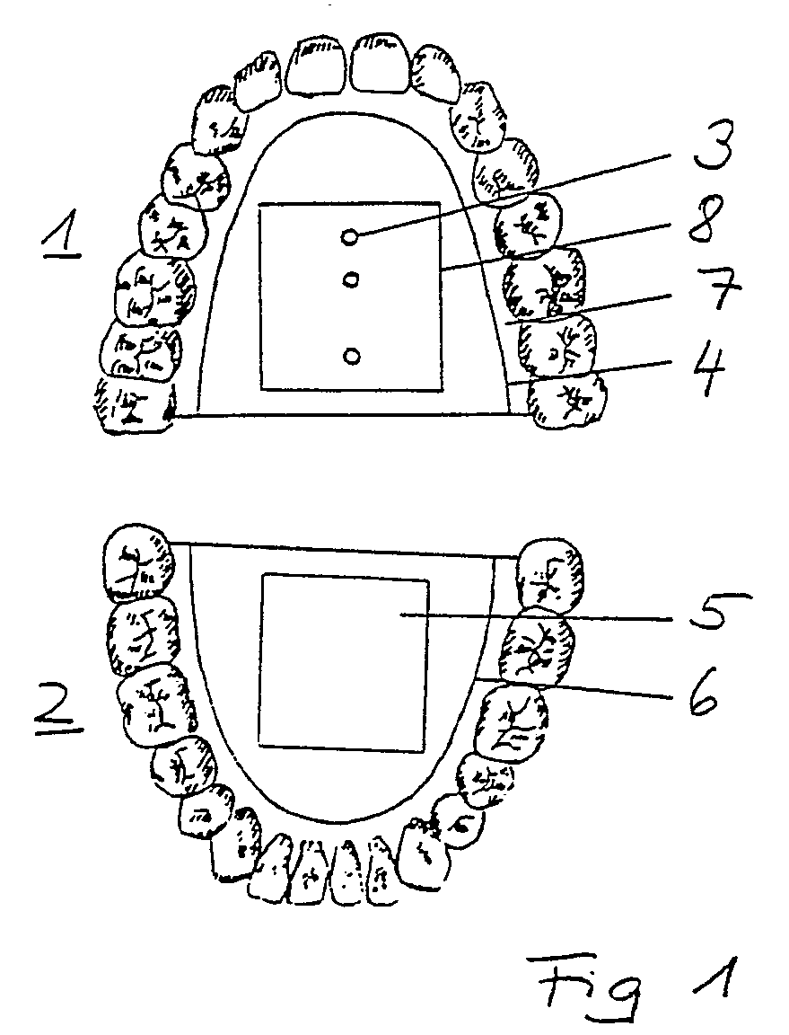
Description
Die Erfindung betrifft eine Vorrichtung zur Analyse der Artikulationsbewegung zwischen Oberkiefer und Unterkiefer, insbesondere unter Kontakt der Zähne von Oberkiefer und Unterkiefer.The invention relates to a device for analyzing the articulation movement between the upper jaw and lower jaw, in particular with contact of the teeth of the upper jaw and lower jaw.
Für die Herstellung von Zahnersatz ist es wesentlich, diesen so zu gestalten, daß die natürliche Artikulationsbewegung des Unterkiefers relativ zum Oberkiefer beibehalten wird und sich die Zähne gegenseitig in geeigneter Weise gegeneinander abstützen. Hierzu wird die individuelle Artikulationsbewegung registriert und in einem geeigneten Artikulator simuliert, in den ein Modell des Patientengebisses eingesetzt wird. Zur Herstellung des Zahnersatzes wird daher immer wieder auf die simulierte Artikulationsbewegung Bezug genommen.For the production of dentures, it is essential to design them in such a way that the natural articulation movement of the lower jaw is maintained relative to the upper jaw and the teeth are mutually supported in a suitable manner. For this purpose, the individual articulation movement is registered and simulated in a suitable articulator in which a model of the patient's dentition is inserted. For the manufacture of the dental prosthesis, reference is therefore repeatedly made to the simulated articulation movement.
Zur Registrierung der Artikulationsbewegung wird eine Meßvorrichtung benutzt, die am Unterkiefer befestigt wird und einen zu den Unterkiefergelenken (Kondylen) ragenden Bügel aufweist. Der sogenannte Kondylenpol wird dabei abgetastet und eine Schreibspitze des Gesichtsbogens auf diesen Punkt ausgerichtet. Unter die Schreibspitze wird ein Registrierungsblatt gelegt, auf das während der Kaubewegung des Patienten die Bewegung der Kondylen aufgezeichnet wird.A measuring device is used to register the articulation movement, which is attached to the lower jaw and has a bracket projecting towards the lower jaw joints (condyles). The so-called condylar pole is scanned and a writing tip of the facebow is aligned with this point. A registration sheet is placed under the tip of the pen, on which the movement of the condyles is recorded while the patient is chewing.
Das übereinstimmend ausgeführte Meßprinzip besteht darin, die Bewegung des Unterkiefers festzustellen, um die individuelle Bewegung des Unterkiefers zum Oberkiefer bei der Herstellung des Zahnersatzes im zahntechnischen Labor möglichst genau zu simulieren. Hierzu sind weiterentwickelte Geräte bekanntgeworden, z. B. der Stereo-Gnathograph-V der Dental-Elektronik KG in 8480 Weiden. Das mechanische Aufzeichnungssystem ist dabei durch ein berührungsloses Bewegungserfassungssystem ersetzt worden, das im Ohrbereich drei Infrarotsender und drei Infrarotempfänger aufweist, zwischen denen eine in geeigneter Weise ausgebildete Platte bewegbar ist, die mit dem Gesichtsbogen verbunden ist. Die Bewegung am kondylenseitigen Ende des Gesichtsbogens wird durch das berührungslose Bewegungserfassungssystem erfaßt und kann elektronisch aufgezeichnet werden. Am eigentlichen Meßprinzip ist hierbei jedoch nichts geändert.The consistent measuring principle consists in determining the movement of the lower jaw in order to simulate the individual movement of the lower jaw to the upper jaw as precisely as possible in the manufacture of the dental prosthesis in the dental laboratory. Further devices have become known for this purpose, e.g. B. the Stereo-Gnathograph-V from Dental-Elektronik KG in 8480 Weiden. The mechanical recording system has been replaced by a non-contact motion detection system that has three infrared transmitters and three infrared receivers in the ear area, between which a suitably designed plate can be moved, which is connected to the facebow. The movement at the condylar end of the facebow is detected by the non-contact movement detection system and can be recorded electronically. However, nothing has changed in the actual measuring principle.
Der Erfindung liegt die Aufgabe zugrunde, eine Vorrichtung der eingangs erwähnten Art so auszubilden, daß eine genaue und zuverlässige Bestimmung der Bewegung des Unterkiefers relativ zum Oberkiefer dadurch möglich ist, daß die Artikulationsbewegung nicht durch am Unterkiefer angebrachte Vorrichtungsteile außerhalb des Mundbereichs gestört wird.The invention has for its object to provide a device of the type mentioned in such a way that an accurate and reliable determination of the movement of the lower jaw relative to the upper jaw is possible in that the articulation movement is not disturbed by parts of the device attached to the lower jaw outside the mouth area.
Diese Aufgabe wird erfindungsgemäß bei einer Vorrichtung der eingangs erwähnten Art gelöst durch zwei in den Oberkiefer und Unterkiefer eingesetzte Platten, die eine Senderanordnung mit mehreren Strahlenquellen und eine Empfängeranordnung zur Detektion von Auftreffpunkten der emittierten Strahlen aufweisen.This object is achieved according to the invention in a device of the type mentioned at the outset by two plates inserted into the upper jaw and lower jaw, which have a transmitter arrangement with a plurality of radiation sources and a receiver arrangement for the detection of impingement points of the emitted beams.
In Abkehr von den durchgängig angewandten Methoden zur Bestimmung der Artikulationsbewegung des Unterkiefers wird nicht die Bewegung des Unterkiefergelenks registriert sondern direkt die an sich interessierende Bewegung der Unterkieferebene zur Oberkieferebene, vor allem unter Zahnkontakt. Durch eine geeignete Anordnung der Strahlenquellen lassen sich Abstandsveränderungen sowie Kippbewegungen durch die Detektion der Auftreffpunkte der emittierten Strahlen mit der Empfängeranordnung ohne weiteres feststellen. Je nach Anwendungsfall kann dabei die Kippbewegung sowohl in Längsrichtung als auch in Querrichtung des Unterkiefers ermittelt werden. Die ungenaue Feststellung der Kondylenbewegung wird daher nicht mehr benötigt.As a departure from the methods used to determine the articulation movement of the lower jaw, it is not the movement of the lower jaw joint that is registered, but rather the movement of the lower jaw plane to the upper jaw plane that is of interest, especially with tooth contact. By means of a suitable arrangement of the radiation sources, changes in distance and tilting movements can easily be determined by the detection of the impingement points of the emitted beams with the receiver arrangement. Depending on the application, the tilting movement can be determined both in the longitudinal direction and in the transverse direction of the lower jaw. The imprecise determination of the condylar movement is therefore no longer required.
Es ist bereits bekannt, für diagnostische Zwecke Platten in den Oberkiefer und Unterkiefer einzupassen. (Schön/Singer (Hrsg.) Europäische Prothetik heute, Buch- und Zeitschriften-Verlag "Die Quintessenz" 1978, Seiten 222 f). Hierbei ist eine der Platten mit einem zentralen spitzen Kegel versehen, der so lang ist, daß beim Zubeißen die Zähne nicht in Kontakt miteinander kommen.It is already known to fit plates in the upper jaw and lower jaw for diagnostic purposes. (Schön / Singer (ed.) European prosthetics today, book and magazine publisher "Die Quintessenz" 1978, pages 222 f). Here, one of the plates is provided with a central pointed cone which is so long that the teeth do not come into contact with one another when biting.
Durch eine Seitwärtsbewegung des Unterkiefers parallel zum Oberkiefer wird eine Kratzspur in Form eines Pfeils auf der Unterkieferplatte erzeugt, die insbesondere an ihren äußeren Enden Aufschlüsse über die Funktion des Kiefergelenks bei der seitlichen Bewegung des Unterkiefers sowie die Erfassung der zentralen Relation der Kiefer anhand der Lage der Pfeilspitzen erlaubt. Die Analyse einer Kaubewegung, bei der die Zähne in Kontakt miteinander geraten, ist dabei weder vorgesehen noch möglich.A sideways movement of the lower jaw parallel to the upper jaw creates a scratch mark in the form of an arrow on the lower jaw plate, which, particularly at its outer ends, provides information about the function of the temporomandibular joint in the lateral movement of the lower jaw and the detection of the central relation of the jaws based on the position of the jaw Arrowheads allowed. The analysis of a chewing movement in which the teeth come into contact with one another is neither provided nor possible.
Es ist möglich, daß bei der erfindungsgemäßen Vorrichtung die Strahlenquellen und die Empfängeranordnung auf derselben Platte angeordnet sind und die zweite Platte lediglich als Reflektor für die emittierten Strahlen fungiert. Bevorzugt ist jedoch die Ausführungsform, in der eine Platte die Senderanordnung (Sender platte) und die andere Platte die Empfängeranordnung (Empfängerplatte) aufweist.It is possible that in the device according to the invention the radiation sources and the receiver arrangement are arranged on the same plate and the second plate only functions as a reflector for the emitted beams. However, the embodiment is preferred in which a plate contains the transmitter arrangement (transmitter plate) and the other plate has the receiver arrangement (receiver plate).
Die Senderanordnung wird im allgemeinen etwas mehr Bauhöhe benötigen als die Empfängeranordnung, so daß es zweckmäßig ist, die Platte mit der Senderanordnung in den Kiefer einzusetzen, wo aufgrund der individuellen anatomischen Situation am meisten Platz vorhanden ist.The transmitter arrangement will generally require slightly more height than the receiver arrangement, so that it is expedient to insert the plate with the transmitter arrangement into the jaw, where there is the most space due to the individual anatomical situation.
Zur Ermittlung der relativen Lage der beiden Platten zueinander sowie einer Kippbewegung in einer Richtung werden vorteilhaft zweit parallel zueinander stehende Strahlenquellen und wenigstens eine dazu schräg stehende Strahlenquelle verwendet. Der Abstand des Auftreffpunktes der schrägstehende Strahlenquelle zu einer der parallel angeordneten Strahlenquellen variiert mit der Entfernung der Platten zueinander. Die Auftreffpunkte der beiden parallel zueinander stehenden Strahlenquellen ermöglichen die Detektion einer planparallelen Verschiebung der Platten zueinander sowie einer relativen Kippbewegung, die zu einer Veränderung des Abstandes zwischen den Auftreffpunkten dieser beiden Strahlenquellen führt. Dabei sind die parallel zueinander stehenden Strahlenquellen vorzugsweise so ausgerichtet, daß sie während des Kontaktes der Zähne von Oberkiefer und Unterkiefer im wesentlichen senkrecht zu der Empfängerplatte stehen.To determine the relative position of the two plates with respect to one another and a tilting movement in one direction, two radiation sources which are parallel to one another and at least one radiation source which is at an angle thereto are advantageously used. The distance between the point of incidence of the inclined radiation source and one of the radiation sources arranged in parallel varies with the distance between the plates. The impingement points of the two radiation sources which are parallel to one another enable the detection of a plane-parallel displacement of the plates relative to one another and a relative tilting movement which leads to a change in the distance between the impingement points of these two radiation sources. The radiation sources which are parallel to one another are preferably oriented such that they are substantially perpendicular to the receiver plate during the contact of the teeth of the upper jaw and lower jaw.
Die Erfindung soll im folgenden an eines in der Zeichnung dargestellten Ausführungsbeispiels näher erläutert werden. Es zeigen:
- Figur 1 - eine Darstellung eines Oberkiefers und eines Unterkiefers mit einer eingesetzten Senderplatte und einer eingesetzten Empfängerplatte
- Figur 2 - einen Prinzipaufbau für drei Lichtquellen auf der Senderplatte relativ zu einem Sensor auf der Empfängerplatte sowie eine prinzipielle Darstellung verschiedender Bewegungen der Platten zueinander.
- Figure 1 - a representation of an upper jaw and a lower jaw with an inserted transmitter plate and an inserted receiver plate
- Figure 2 - a basic structure for three light sources on the transmitter plate relative to a sensor on the receiver plate and a basic representation of different movements of the plates to each other.
Figur 1 zeigt einen Oberkiefer 1 und einen Unterkiefer 2. In den Oberkiefer 1 ist eine Strahlenquellen 3 tragende erste Platte 4 eingesetzt, die als Senderplatte fungiert, während in den Unterkiefer 2 eine eine Sensorfläche 5 tragende Platte 6 eingesetzt ist. Beide Platten 4, 6 sind mit geeignetem Ausgleichsmaterial 7 eingepaßt.FIG. 1 shows an
Die erste Platte 4 (Senderplatte) hält eine Trägerplatte 8, die drei als Strahlenquellen fungierende Lichtquellen 3 trägt.The first plate 4 (transmitter plate) holds a carrier plate 8 which carries three
Die im Unterkiefer eingesetzte zweite Platte 6 (Empfängerplatte) trägt eine Sensorfläche 5, die die Detektion von Auftreffpunkten der Lichtstrahlen mit den Koordinaten auf der Sensorfläche 5 ermöglicht. Hierzu wird die Sensorfläche 5 zeilenförmig abgetastet, wobei jedem Auftreffpunkt ein definierter elektrischer Wert zugeordnet ist.The second plate 6 (receiver plate) inserted in the lower jaw carries a
Figur 2 zeigt in der Abbildung A eine Prinzipanordnung für drei Strahlenquellen 3, die hier als Lichtquellen L1, L2, L3 ausgebildet sind. Diese drei Lichtquellen müssen keine selbständige Lichterzeuger sein, sondern können beispielsweise durch Licht leiter gebildet sein, denen von einem gemeinsamen Lichtgenerator Lichtsignale zugeleitet werden. In einfacher Weise können aber auch normale Glühlampen, Leuchtdioden oder vorzugsweise Laserdioden als Lichtquellen L1, L2, L3 eingesetzt werden.Figure 2 shows in Figure A a basic arrangement for three
Die drei auf der Senderplatte 4 befestigten Lichtquellen L1, L2, L3 sind so angeordnet, daß zwei der Lichtquellen, nämlich L1 und L3 parallel zueinander stehen, während eine mittlere, auf der Verbindungslinie der beiden Lichtquellen L1, L3 angeordnete Lichtquelle L2 schräg dazu abstrahlt.The three light sources L1, L2, L3 fastened on the transmitter plate 4 are arranged such that two of the light sources, namely L1 and L3, are parallel to one another, while a middle light source L2 arranged on the connecting line of the two light sources L1, L3 emits obliquely to it.
Die drei Lichtquellen erzeugen auf der Sensorfläche 5 Auftreffpunkte A1, A2, A3, deren Lage durch die Sensorfläche 5 detektiert wird.The three light sources generate points of incidence A1, A2, A3 on the
Wie Abbildung B der Figur 2 zeigt, wird für eine Entfernungsmessung nur das Licht der Lichtquellen L1, L2 benötigt. Wandert die Sensorfläche 5, und damit der Unterkiefer 2 näher an die Senderplatte 4, und damit an den Oberkiefer 1 heran, vergrößert sich der Abstand zwischen den Auftreffpunkten A1′, A2′ der Lichtquellen L1, L2, wenn sich die Strahlen der Lichtquellen L1, L2 in der Ausgangsstellung nicht geschnitten haben.As Figure B of Figure 2 shows, only the light of the light sources L1, L2 is required for a distance measurement. If the sensor surface 5, and thus the lower jaw 2 moves closer to the transmitter plate 4, and thus to the
In Abbildung C ist dargestellt, daß für die Feststellung einer Verschiebung der Sensorfläche 5 nur ein Auftreffpunkt benötigt wird. Die Lage beispielsweise des Auftreffpunktes A3 auf der Sensorfläche 5 ändert sich, wenn diese parallel zu sich selbst verschoben wird, wie dies durch den Auftreffpunkt A3′ verdeutlicht ist.Figure C shows that only one point of impact is required to detect a shift in
Abbildung D zeigt die Detektion einer Neigung der beiden Platten 4, 6 zueinander. Die beiden parallel zueinander stehenden Lichtquellen L1, L3 erzeugen bei einer parallelen Ausrichtung der beiden Platten 4, 6 zueinander Auftreffpunkte A1, A3, deren Abstand dem Abstand der Lichtquellen L1, L3 entspricht. Wird die Sensorfläche 5 relativ zu der Senderplatte 4 geneigt, entstehen Auftreffpunkte A1˝, A3˝, deren Abstand voneinander sich proportional zur Neigung in Richtung der Verbindungslinie der beiden Lichtquellen L1, L3 vergrößert. Selbstverständlich ist für die relative Neigungsbestimmung nicht erforderlich, daß die beiden Platten 4, 6 in der Ausgangslage völlig parallel zueinander stehen.Figure D shows the detection of an inclination of the two plates 4, 6 to one another. When the two plates 4, 6 are aligned parallel to one another, the two light sources L1, L3, which are parallel to one another, produce impact points A1, A3, their Distance corresponds to the distance between the light sources L1, L3. If the
Die in Figur 2 dargestellte Anordnung dient zur Detektion der relativen Bewegungen von Unterkiefer zu Oberkiefer entlang einer Detektionslinie. Eine dreidimensionale Detektion der Bewegung ist durch entsprechende Ergänzung von Lichtqellen, beispielsweise senkrecht zu der Verbindungslinie der Lichtquellen L1, L2, L3 ohne weiteres möglich.The arrangement shown in FIG. 2 serves to detect the relative movements from lower jaw to upper jaw along a detection line. A three-dimensional detection of the movement is easily possible by appropriately supplementing light sources, for example perpendicular to the connecting line of the light sources L1, L2, L3.
Die Auswertung der ermittelten Meßwerte während eines Bewegungsvorganges wird von einem Rechner vorgenommen. Die Wiedergabe der ermittelten Bewegung ist ohne weiteres in zwei- oder drei-dimensionaler Form möglich.The evaluation of the measured values determined during a movement process is carried out by a computer. The determined movement can easily be reproduced in two or three dimensions.
Claims (4)
Priority Applications (1)
| Application Number | Priority Date | Filing Date | Title |
|---|---|---|---|
| AT89102843T ATE91401T1 (en) | 1988-02-26 | 1989-02-18 | DEVICE FOR ANALYZING THE MOVEMENT OF ARTICULATION BETWEEN THE MAXILLA AND THE LOWER JAW. |
Applications Claiming Priority (2)
| Application Number | Priority Date | Filing Date | Title |
|---|---|---|---|
| DE3806028 | 1988-02-26 | ||
| DE3806028A DE3806028C1 (en) | 1988-02-26 | 1988-02-26 |
Publications (3)
| Publication Number | Publication Date |
|---|---|
| EP0330101A2 true EP0330101A2 (en) | 1989-08-30 |
| EP0330101A3 EP0330101A3 (en) | 1990-06-27 |
| EP0330101B1 EP0330101B1 (en) | 1993-07-14 |
Family
ID=6348215
Family Applications (1)
| Application Number | Title | Priority Date | Filing Date |
|---|---|---|---|
| EP89102843A Expired - Lifetime EP0330101B1 (en) | 1988-02-26 | 1989-02-18 | Device for analysis of articulation between upper and lower jaws |
Country Status (4)
| Country | Link |
|---|---|
| EP (1) | EP0330101B1 (en) |
| AT (1) | ATE91401T1 (en) |
| DE (2) | DE3806028C1 (en) |
| ES (1) | ES2041851T3 (en) |
Cited By (2)
| Publication number | Priority date | Publication date | Assignee | Title |
|---|---|---|---|---|
| DE10218435B4 (en) * | 2002-04-25 | 2010-03-04 | Zebris Medical Gmbh | Method and device for 3-dimensional movement analysis of tooth surfaces of the upper jaw in relation to the lower jaw |
| WO2011147988A2 (en) | 2010-05-28 | 2011-12-01 | Zebris Medical Gmbh | Dental tool |
Families Citing this family (7)
| Publication number | Priority date | Publication date | Assignee | Title |
|---|---|---|---|---|
| DE3907444C1 (en) * | 1989-03-08 | 1990-08-09 | Dental-Labor Werner Puckert, 4236 Hamminkeln, De | Device for recording the vertical dimension and central occlusion in total or partial occlusion disturbance |
| DD297059A5 (en) * | 1990-08-14 | 1992-01-02 | �������`�����`������������k�� | DEVICE FOR THE TWO-DIMENSIONAL INTRAORAL REGISTRATION OF THE UNDERGROUND MOVEMENT AND THE DEEPER FORCE |
| DE19830617C1 (en) * | 1998-07-09 | 1999-09-09 | Ars Dental Gmbh | Jaw articulation analysis device for use in dental prosthetics |
| DE10004226C1 (en) * | 2000-02-01 | 2001-07-05 | Ars Dental Gmbh | Articulation analysis device has light sources forming triangle on transmitter plate with light incident at point for one distance between receiver and transmitter arrangements on jaw plates |
| DE102006011787A1 (en) * | 2006-03-15 | 2007-09-20 | Rahnenführer, Claus | Jaw`s e.g. upper jaw, three-dimensional movement measuring device, has photosensitive sensor detecting contact area points on convex-curved and curved two-way measuring surfaces, provided on retainer and two-way retainer, respectively |
| DE102012001653B4 (en) | 2011-03-25 | 2021-06-24 | Andreas Vogel | Device and method for measuring mandibular movements guided by the mandibular joint |
| DE102016120583B3 (en) * | 2016-10-27 | 2018-04-12 | Sicat Gmbh & Co. Kg | Method for recording jaw movements |
Family Cites Families (4)
| Publication number | Priority date | Publication date | Assignee | Title |
|---|---|---|---|---|
| US3390459A (en) * | 1959-09-17 | 1968-07-02 | Seidenberg Murray | Dental apparatus and method |
| US4234306A (en) * | 1979-07-18 | 1980-11-18 | Hbti | Method and apparatus for sensing jaw position and movements and utilizing sensed data |
| DE2936328A1 (en) * | 1979-09-08 | 1981-03-12 | Becker Dental-Labor Gmbh, 5100 Aachen | METHOD AND DEVICE FOR REPRODUCING Jaw Movement. |
| JPS58175544A (en) * | 1982-04-07 | 1983-10-14 | 株式会社モリタ製作所 | Lower mandible motion diagnostic apparatus |
-
1988
- 1988-02-26 DE DE3806028A patent/DE3806028C1/de not_active Expired
-
1989
- 1989-02-18 AT AT89102843T patent/ATE91401T1/en not_active IP Right Cessation
- 1989-02-18 DE DE8989102843T patent/DE58904888D1/en not_active Expired - Fee Related
- 1989-02-18 ES ES198989102843T patent/ES2041851T3/en not_active Expired - Lifetime
- 1989-02-18 EP EP89102843A patent/EP0330101B1/en not_active Expired - Lifetime
Cited By (3)
| Publication number | Priority date | Publication date | Assignee | Title |
|---|---|---|---|---|
| DE10218435B4 (en) * | 2002-04-25 | 2010-03-04 | Zebris Medical Gmbh | Method and device for 3-dimensional movement analysis of tooth surfaces of the upper jaw in relation to the lower jaw |
| WO2011147988A2 (en) | 2010-05-28 | 2011-12-01 | Zebris Medical Gmbh | Dental tool |
| DE102010021934A1 (en) | 2010-05-28 | 2011-12-01 | Zebris Medical Gmbh | Dental tool |
Also Published As
| Publication number | Publication date |
|---|---|
| ATE91401T1 (en) | 1993-07-15 |
| EP0330101A3 (en) | 1990-06-27 |
| EP0330101B1 (en) | 1993-07-14 |
| DE58904888D1 (en) | 1993-08-19 |
| DE3806028C1 (en) | 1989-05-18 |
| ES2041851T3 (en) | 1993-12-01 |
Similar Documents
| Publication | Publication Date | Title |
|---|---|---|
| EP2099383B1 (en) | Method and device for the transfer of a jaw model in relation to a hinge axis | |
| DE3500605A1 (en) | DEVICE FOR MEASURING THE POSITIONS AND MOVEMENTS OF THE LOWER JAW RELATIVE TO THE UPPER JAW | |
| DE2439125A1 (en) | DEVICE FOR DENTISTRY | |
| EP3422996B1 (en) | Device and method for measuring a movement of a mandible | |
| DE3807578C2 (en) | ||
| EP0330101B1 (en) | Device for analysis of articulation between upper and lower jaws | |
| WO2018130656A1 (en) | Device and method for measuring a movement of a mandible | |
| CH643728A5 (en) | SENSOR DEVICE FOR MANDIBULAR MOVEMENTS. | |
| EP0371272B1 (en) | Device for determining the centric occlusion of molars | |
| DE102004002953B4 (en) | Method and device for determining all degrees of freedom of movement and positions of the lower jaw with respect to the upper jaw | |
| DD297059A5 (en) | DEVICE FOR THE TWO-DIMENSIONAL INTRAORAL REGISTRATION OF THE UNDERGROUND MOVEMENT AND THE DEEPER FORCE | |
| DE2825204C2 (en) | Device for the three-dimensional detection and recording of the movement of the temporomandibular joints of a patient | |
| DE102013109180B3 (en) | Apparatus and method for detecting jaw-guided lower jaw movement, articulator and method for simulating jaw movement on an articulator | |
| DE2950847C2 (en) | Dental device for detecting the spatial position and movement of the human lower jaw in relation to the patient's skull reference plane | |
| EP0332892B1 (en) | Device for determining the relative movement of two measuring positions | |
| EP1650529A1 (en) | Device and method for scanning multiple objects | |
| DE3123526C2 (en) | Method for one to three-dimensional measurement of jaw and jaw joint movements and arrangement for carrying out the method | |
| EP0229266A2 (en) | Reconstruction method for the upper jaw teeth | |
| DE10004226C1 (en) | Articulation analysis device has light sources forming triangle on transmitter plate with light incident at point for one distance between receiver and transmitter arrangements on jaw plates | |
| DE19830617C1 (en) | Jaw articulation analysis device for use in dental prosthetics | |
| DE10236333A1 (en) | Jaw articulation analysis device comprises a sensor support arrangement with a brace for mounting on the upper or lower teeth and a holder for the sensor arrangement itself that enables it to be positioned outside the mouth | |
| DE102009055848B4 (en) | Method for the determination and automated correction of the joint space situation in the region of the jaw of a patient and for a suitable joint space tool | |
| DE2832838C2 (en) | Dental pantography device and associated partially adjustable articulator | |
| DE102015101147A1 (en) | Method and device for determining values of a dentition | |
| DE3002267A1 (en) | Human jaw movement determination method - using electronic measurement detectors for movement of bottom jaw |
Legal Events
| Date | Code | Title | Description |
|---|---|---|---|
| PUAI | Public reference made under article 153(3) epc to a published international application that has entered the european phase |
Free format text: ORIGINAL CODE: 0009012 |
|
| AK | Designated contracting states |
Kind code of ref document: A2 Designated state(s): AT BE CH DE ES FR GB GR IT LI LU NL SE |
|
| PUAL | Search report despatched |
Free format text: ORIGINAL CODE: 0009013 |
|
| RHK1 | Main classification (correction) |
Ipc: A61C 19/04 |
|
| AK | Designated contracting states |
Kind code of ref document: A3 Designated state(s): AT BE CH DE ES FR GB GR IT LI LU NL SE |
|
| 17P | Request for examination filed |
Effective date: 19901210 |
|
| 17Q | First examination report despatched |
Effective date: 19920423 |
|
| GRAA | (expected) grant |
Free format text: ORIGINAL CODE: 0009210 |
|
| AK | Designated contracting states |
Kind code of ref document: B1 Designated state(s): AT BE CH DE ES FR GB GR IT LI LU NL SE |
|
| REF | Corresponds to: |
Ref document number: 91401 Country of ref document: AT Date of ref document: 19930715 Kind code of ref document: T |
|
| GBT | Gb: translation of ep patent filed (gb section 77(6)(a)/1977) |
Effective date: 19930712 |
|
| REF | Corresponds to: |
Ref document number: 58904888 Country of ref document: DE Date of ref document: 19930819 |
|
| ET | Fr: translation filed | ||
| ITF | It: translation for a ep patent filed | ||
| REG | Reference to a national code |
Ref country code: GR Ref legal event code: FG4A Free format text: 3008872 |
|
| REG | Reference to a national code |
Ref country code: ES Ref legal event code: FG2A Ref document number: 2041851 Country of ref document: ES Kind code of ref document: T3 |
|
| EPTA | Lu: last paid annual fee | ||
| PLBE | No opposition filed within time limit |
Free format text: ORIGINAL CODE: 0009261 |
|
| STAA | Information on the status of an ep patent application or granted ep patent |
Free format text: STATUS: NO OPPOSITION FILED WITHIN TIME LIMIT |
|
| 26N | No opposition filed | ||
| EAL | Se: european patent in force in sweden |
Ref document number: 89102843.3 |
|
| PGFP | Annual fee paid to national office [announced via postgrant information from national office to epo] |
Ref country code: LU Payment date: 19950201 Year of fee payment: 7 |
|
| PGFP | Annual fee paid to national office [announced via postgrant information from national office to epo] |
Ref country code: SE Payment date: 19950215 Year of fee payment: 7 |
|
| PGFP | Annual fee paid to national office [announced via postgrant information from national office to epo] |
Ref country code: GR Payment date: 19950216 Year of fee payment: 7 |
|
| PGFP | Annual fee paid to national office [announced via postgrant information from national office to epo] |
Ref country code: NL Payment date: 19950228 Year of fee payment: 7 Ref country code: ES Payment date: 19950228 Year of fee payment: 7 Ref country code: AT Payment date: 19950228 Year of fee payment: 7 |
|
| PGFP | Annual fee paid to national office [announced via postgrant information from national office to epo] |
Ref country code: BE Payment date: 19950301 Year of fee payment: 7 |
|
| PG25 | Lapsed in a contracting state [announced via postgrant information from national office to epo] |
Ref country code: LU Free format text: LAPSE BECAUSE OF NON-PAYMENT OF DUE FEES Effective date: 19960218 Ref country code: AT Effective date: 19960218 |
|
| PG25 | Lapsed in a contracting state [announced via postgrant information from national office to epo] |
Ref country code: SE Effective date: 19960219 Ref country code: ES Free format text: LAPSE BECAUSE OF NON-PAYMENT OF DUE FEES Effective date: 19960219 |
|
| PG25 | Lapsed in a contracting state [announced via postgrant information from national office to epo] |
Ref country code: BE Effective date: 19960228 |
|
| BERE | Be: lapsed |
Owner name: SCHRADER ERHARD Effective date: 19960228 |
|
| PG25 | Lapsed in a contracting state [announced via postgrant information from national office to epo] |
Ref country code: GR Free format text: THE PATENT HAS BEEN ANNULLED BY A DECISION OF A NATIONAL AUTHORITY Effective date: 19960831 |
|
| PG25 | Lapsed in a contracting state [announced via postgrant information from national office to epo] |
Ref country code: NL Effective date: 19960901 |
|
| REG | Reference to a national code |
Ref country code: GR Ref legal event code: MM2A Free format text: 3008872 |
|
| NLV4 | Nl: lapsed or anulled due to non-payment of the annual fee |
Effective date: 19960901 |
|
| PGFP | Annual fee paid to national office [announced via postgrant information from national office to epo] |
Ref country code: CH Payment date: 19980220 Year of fee payment: 10 |
|
| PGFP | Annual fee paid to national office [announced via postgrant information from national office to epo] |
Ref country code: GB Payment date: 19990204 Year of fee payment: 11 |
|
| PGFP | Annual fee paid to national office [announced via postgrant information from national office to epo] |
Ref country code: DE Payment date: 19990205 Year of fee payment: 11 |
|
| PGFP | Annual fee paid to national office [announced via postgrant information from national office to epo] |
Ref country code: FR Payment date: 19990215 Year of fee payment: 11 |
|
| PG25 | Lapsed in a contracting state [announced via postgrant information from national office to epo] |
Ref country code: LI Free format text: LAPSE BECAUSE OF NON-PAYMENT OF DUE FEES Effective date: 19990228 Ref country code: CH Free format text: LAPSE BECAUSE OF NON-PAYMENT OF DUE FEES Effective date: 19990228 |
|
| REG | Reference to a national code |
Ref country code: ES Ref legal event code: FD2A Effective date: 19990301 |
|
| REG | Reference to a national code |
Ref country code: CH Ref legal event code: PL |
|
| PG25 | Lapsed in a contracting state [announced via postgrant information from national office to epo] |
Ref country code: GB Free format text: LAPSE BECAUSE OF NON-PAYMENT OF DUE FEES Effective date: 20000218 |
|
| GBPC | Gb: european patent ceased through non-payment of renewal fee |
Effective date: 20000218 |
|
| PG25 | Lapsed in a contracting state [announced via postgrant information from national office to epo] |
Ref country code: FR Free format text: LAPSE BECAUSE OF NON-PAYMENT OF DUE FEES Effective date: 20001031 |
|
| PG25 | Lapsed in a contracting state [announced via postgrant information from national office to epo] |
Ref country code: DE Free format text: LAPSE BECAUSE OF NON-PAYMENT OF DUE FEES Effective date: 20001201 |
|
| REG | Reference to a national code |
Ref country code: FR Ref legal event code: ST |
|
| PG25 | Lapsed in a contracting state [announced via postgrant information from national office to epo] |
Ref country code: IT Free format text: LAPSE BECAUSE OF NON-PAYMENT OF DUE FEES;WARNING: LAPSES OF ITALIAN PATENTS WITH EFFECTIVE DATE BEFORE 2007 MAY HAVE OCCURRED AT ANY TIME BEFORE 2007. THE CORRECT EFFECTIVE DATE MAY BE DIFFERENT FROM THE ONE RECORDED. Effective date: 20050218 |