EP0330032A1 - Dosierungseinheit für die Komponenten eines injizierbaren Harzes - Google Patents
Dosierungseinheit für die Komponenten eines injizierbaren Harzes Download PDFInfo
- Publication number
- EP0330032A1 EP0330032A1 EP89102413A EP89102413A EP0330032A1 EP 0330032 A1 EP0330032 A1 EP 0330032A1 EP 89102413 A EP89102413 A EP 89102413A EP 89102413 A EP89102413 A EP 89102413A EP 0330032 A1 EP0330032 A1 EP 0330032A1
- Authority
- EP
- European Patent Office
- Prior art keywords
- dosage
- cylinder
- piston
- unit
- pressure
- Prior art date
- Legal status (The legal status is an assumption and is not a legal conclusion. Google has not performed a legal analysis and makes no representation as to the accuracy of the status listed.)
- Withdrawn
Links
Images
Classifications
-
- B—PERFORMING OPERATIONS; TRANSPORTING
- B29—WORKING OF PLASTICS; WORKING OF SUBSTANCES IN A PLASTIC STATE IN GENERAL
- B29B—PREPARATION OR PRETREATMENT OF THE MATERIAL TO BE SHAPED; MAKING GRANULES OR PREFORMS; RECOVERY OF PLASTICS OR OTHER CONSTITUENTS OF WASTE MATERIAL CONTAINING PLASTICS
- B29B7/00—Mixing; Kneading
- B29B7/30—Mixing; Kneading continuous, with mechanical mixing or kneading devices
- B29B7/58—Component parts, details or accessories; Auxiliary operations
- B29B7/60—Component parts, details or accessories; Auxiliary operations for feeding, e.g. end guides for the incoming material
- B29B7/603—Component parts, details or accessories; Auxiliary operations for feeding, e.g. end guides for the incoming material in measured doses, e.g. proportioning of several materials
-
- B—PERFORMING OPERATIONS; TRANSPORTING
- B01—PHYSICAL OR CHEMICAL PROCESSES OR APPARATUS IN GENERAL
- B01F—MIXING, e.g. DISSOLVING, EMULSIFYING OR DISPERSING
- B01F35/00—Accessories for mixers; Auxiliary operations or auxiliary devices; Parts or details of general application
- B01F35/71—Feed mechanisms
- B01F35/717—Feed mechanisms characterised by the means for feeding the components to the mixer
- B01F35/7174—Feed mechanisms characterised by the means for feeding the components to the mixer using pistons, plungers or syringes
-
- B—PERFORMING OPERATIONS; TRANSPORTING
- B01—PHYSICAL OR CHEMICAL PROCESSES OR APPARATUS IN GENERAL
- B01F—MIXING, e.g. DISSOLVING, EMULSIFYING OR DISPERSING
- B01F35/00—Accessories for mixers; Auxiliary operations or auxiliary devices; Parts or details of general application
- B01F35/80—Forming a predetermined ratio of the substances to be mixed
- B01F35/88—Forming a predetermined ratio of the substances to be mixed by feeding the materials batchwise
- B01F35/882—Forming a predetermined ratio of the substances to be mixed by feeding the materials batchwise using measuring chambers, e.g. volumetric pumps, for feeding the substances
- B01F35/8822—Forming a predetermined ratio of the substances to be mixed by feeding the materials batchwise using measuring chambers, e.g. volumetric pumps, for feeding the substances using measuring chambers of the piston or plunger type
-
- B—PERFORMING OPERATIONS; TRANSPORTING
- B29—WORKING OF PLASTICS; WORKING OF SUBSTANCES IN A PLASTIC STATE IN GENERAL
- B29B—PREPARATION OR PRETREATMENT OF THE MATERIAL TO BE SHAPED; MAKING GRANULES OR PREFORMS; RECOVERY OF PLASTICS OR OTHER CONSTITUENTS OF WASTE MATERIAL CONTAINING PLASTICS
- B29B7/00—Mixing; Kneading
- B29B7/30—Mixing; Kneading continuous, with mechanical mixing or kneading devices
- B29B7/58—Component parts, details or accessories; Auxiliary operations
- B29B7/72—Measuring, controlling or regulating
Definitions
- the present invention relates to a dosage unit for components of an injectable resin particularly but not exclusively of the polyurethane type.
- Dosage units which have dosage cylinders operated by actuator systems with oleodynamic cylinders; their operation is controlled by means of position transducers and servo-valve units associated with a computerized control unit. These systems satisfactorily perform the tasks for which they are intended, but they have the disadvantage of being considerably complicated, expensive and difficult as regards maintenance.
- the aim of the present invention is to obviate the above described disadvantages by providing a dosage unit having combined control systems with high operating precision and reliability.
- an object of the invention is to provide a dosage unit using a simple and high-efficiency actuation and control system.
- a further object of the invention is to provide a dosage unit requiring reduced installed power.
- a further object of the present invention is to obtain a dosage unit having a limited use of maximum power and with very low energy dispersion, with consequent characteristics of economy and environment protection.
- Not least object of the invention is to provide a dosage unit having a low maintenance cost.
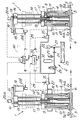
- a dosage machine comprising two dosage units, each indicated as a whole by the reference numeral 1, associated with an oleodynamic control unit indicated at 2.
- each dosage unit 1 comprises a supporting frame 3 for at least one dosage cylinder 4 having a feed duct 5 fitted with a choke valve 5a and a discharge duct 6 fitted with a choke valve 6a.
- the piston 7 upwardly supported by the crosspiece 8 fitted with sealing rings 9 is sealingly slidable inside the dosage cylinder 4.
- actuation means act on the piston 7 for moving it as required to fill and empty the dosage cylinder 4.
- an actuator element acts on the piston 7 to impart thereto the power required to empty the dosage cylinder 4.
- the piston 7 is upwardly rigidly associated with the connecting plate 12 which is rigidly coupled at its two ends with one or two plungers 11 sliding in respective oleodynamic cylinders 10 mounted with their longitudinal axes parallel to the dosage cylinder 4 and to the piston 7.
- the oleodynamic cylinders 10 are connected to the oleodynamic control unit 2 by means of the ducts 35.
- the actuation means of the piston 7 advantageously comprise a control element acting on the piston 7 to impart thereto a controlled speed in the dosage cylinder 4.
- a threaded bush 13 is inserted at the center of the connecting plate 12 coaxially to the piston 7, and an actuation screw 14 engages in said bush.
- Said actuation screw is upwardly supported by a bearing 15 inserted in an upper connecting plate 16 rigidly associated with the crosspiece 8 by two sliding columns 17 which also act as guiding elements for the connecting plate 12.
- the actuation screw 14 is rotated by the direct-current motor 18 by means of a pulley 19.
- An angular speed transducer or encoder 20a is mounted on the actuation screw 14 and a device 20b for adjusting the rotation rate, such as a speedometer dynamo, is keyed on the axis of the motor 18.
- the output signal of the encoder 20a is sent to a first control unit 20 which compares it with a reference signal V REF which corresponds to a preset rotation rate of the screw 14 and thus to a preset advancement of the piston 7.
- the resulting error signal is pre-amplified and used to drive the adjustment device 20b so as to obtain a controlled advancement speed for the piston 7.
- the actuation screw 14 is of the non-reversible type, i.e. it is adapted to impart an advancing motion to the threaded bush with which it engages but not to rotate as an effect of the movement of the bush 13. It may furthermore possibly be a ball-screw or have another lubricating means.
- the actuator element acting on the piston is separate and operatively independent from the element controlling its speed of advancement relatively to the dosage cylinder 4.
- the power of the actuation motor of the actuation screw 14 is conveniently at least sufficient to overcome the frictions between said actuation screw and the threaded bush 13, but does not contribute substantially to provide the power required to actuate the piston 7 to empty the dosage cylinder 4.
- said unit is composed of a pump 21 actuated by an AC motor 22 which draws oil from a collection tank 23.
- a non-return valve 24, a safety valve 25 and a driven reflow valve 26 are arranged on the delivery circuit.
- a servo-controlled electric valve 27 is interposed between said driven valve 26 and the feed duct 35 of the oleodynamic cylinders 10 to adjust the delivery pressure for said oleodynamic cylinders 10.
- An element for controlling the pressure acting on the adjustment valve 27 is advantageously provided to keep constant the difference between the pressure of the component leaving said dosage cylinder and the delivery pressure of the oil at the input of the actuator cylinders 10.
- a pressure transducer 28 is arranged on the discharge duct 6 of the dosage cylinder 4 and is connected to a second electronic comparator unit 30 by means of the electric line 29.
- a preset differential value ⁇ determined by experimental tests, on the electronic comparator unit 30.
- the sum signal of said partial signals, processed by the electronic unit 30 and conveniently amplified, is used to drive the servo-control of the adjustment valve 27, which determines the pressure required to move the piston 7 in the feed duct of the oleodynamic cylinders 10, said pressure being variable in each instance according to the conditions required inside the mixing chamber.
- At least one energy storing unit is conveniently arranged after the pump of the oleodynamic control unit, said unit having the task of storing the oleodynamic energy transmitted to the oleodynamic control unit in the reflow of the oil from said actuator during the filling of the dosage cylinder, which is performed by external component-filling means.
- one or more hydropneumatic accumulators 31 with oil-gas separation membrane are inserted between the non-return valve 24 and the safety valve 26.
- the gas confined above the oil-gas separation membrane normally nitrogen, is compressed by the pump 21 during the refilling of the dosage cylinders 7 and during the pause between one flow casting and the next and can return its potential energy during the successive actuation of the oleodynamic cylinders 10, which work is predominantly performed by the motor 22 of the oleodynamic control unit.
- the reflow of the oil towards the oleodynamic control unit is partially performed by virtue of the pressure exerted on the piston 7 by the component introduced in the dosage cylinder through the feed duct 5 from an external pressurized tank, not illustrated, and partially by virtue of the energy supplied by the actuation screw 14 actuated by the motor 20.
- the flow-rate of the oil during refilling can remain within rather limited values, but acts over a period, on the order of 15-20 sec, which is rather long if compared with the approximately 5-sec duration of the discharge of the dosage cylinder.
- the comparator units 20 and 30, though acting on independent parameters, are combined in a single central control unit (schematically indicated at 40) together with other system control devices to which the present invention does not relate.
- the oleodynamic control unit can have a very limited power in kW, since power is accumulated during idle phases of the dosage machine, which are always longer than the working ones.
- the component mixing time and consequently the speed of advancement of the piston 7 in the dosage cylinder 4 are initially preset through the central control unit which correspondingly generates a voltage V REF supplied to the device 20 for controlling the rotation rate of the motor 18 or of the actuation screw 14.
- the pressure differential ⁇ which is desired between the delivery of the oil in the oleodynamic cylinders 10 and the output pressure of the dosage cylinder is furthermore preset through the central unit.
- the dosage cylinder is then filled by opening the choke valve 5a on the duct 5 for feeding the component to the dosage cylinder 4 and by turning the actuation screw 14 in the opposed direction with respect to the discharge phase.
- the oil contained in the oleodynamic cylinders 10 flows back towards the oleodynamic control unit 2 and the pump 21 charges the accumulators 31.
- the mixing phase begins by actuating both the pump of the oleodynamic control unit and the motor 18 of the actuation screw 14, which operate independently and are correlated by the above mentioned operating parameters.
- the dosage unit according to the invention fully achieves the intended aim since, by virtue of the precision and simplicity of the screw adjustment system together with the power provided by the oleodynamic actuation system, the dosage of components to be mixed can be obtained accurately and reliably.
- the systems for balancing the delivery pressure in the feed circuit of the oleodynamic cylinders 10 and the system for storing energy in the hydropneumatic accumulators furthermore save a considerable amount of energy, reduce dissipations in the form of heat, and reduce the management and maintenance costs of the machine.
- the materials employed, as well as the dimensions, may be any according to the requirements and to the state of the art.
Landscapes
- Chemical & Material Sciences (AREA)
- Chemical Kinetics & Catalysis (AREA)
- Engineering & Computer Science (AREA)
- Mechanical Engineering (AREA)
- Infusion, Injection, And Reservoir Apparatuses (AREA)
Applications Claiming Priority (2)
| Application Number | Priority Date | Filing Date | Title |
|---|---|---|---|
| IT1957088 | 1988-02-26 | ||
| IT8819570A IT1216469B (it) | 1988-02-26 | 1988-02-26 | Gruppo di dosaggio per la miscelazione di componenti di una resina iniettabile. |
Publications (1)
| Publication Number | Publication Date |
|---|---|
| EP0330032A1 true EP0330032A1 (de) | 1989-08-30 |
Family
ID=11159147
Family Applications (1)
| Application Number | Title | Priority Date | Filing Date |
|---|---|---|---|
| EP89102413A Withdrawn EP0330032A1 (de) | 1988-02-26 | 1989-02-13 | Dosierungseinheit für die Komponenten eines injizierbaren Harzes |
Country Status (2)
| Country | Link |
|---|---|
| EP (1) | EP0330032A1 (de) |
| IT (1) | IT1216469B (de) |
Cited By (7)
| Publication number | Priority date | Publication date | Assignee | Title |
|---|---|---|---|---|
| EP0482579A1 (de) * | 1990-10-22 | 1992-04-29 | Reinhardt-Technik GmbH & Co. | Verfahren und Vorrichtung zum Dosieren eines insbesondere hochviskosen Ein- oder Mehrkomponentengemisches |
| WO1992010281A1 (en) * | 1990-12-14 | 1992-06-25 | Eastman Kodak Company | Liquids mixing and dispensing system |
| EP0628390A1 (de) * | 1993-06-08 | 1994-12-14 | MICAFIL Vakuumtechnik AG | Dosier- und Förderpumpe und Verwendung einer solchen Pumpe in einer Anlage zur Herstellung eines Giessharzkörpers |
| ES2064183A2 (es) * | 1992-02-27 | 1995-01-16 | Murgui Jose Maria Razquin | Sistema para mantenimiento de la presion en instalaciones suministradoras de materiales viscosos. |
| EP0644025A1 (de) * | 1993-09-22 | 1995-03-22 | WIWA WILHELM WAGNER GMBH & CO. KG | Verfahren zum Mischen von Werkstoffkomponenten und Vorrichtung zur Durchführung des Verfahrens |
| EP0674540A4 (de) * | 1992-09-22 | 1995-08-08 | Reagent Chemical And Res Inc | Mischapparat und verfahren zur herstellung eines zusammengestzten materials aus einer mehrzahl von komponenten. |
| FR2978678A1 (fr) * | 2011-08-02 | 2013-02-08 | Ascodero Productique | Procede de dosage et de melange en continu de deux produits et dispositif de dosage et de melange en tant que tel |
Citations (5)
| Publication number | Priority date | Publication date | Assignee | Title |
|---|---|---|---|---|
| US2960925A (en) * | 1955-09-09 | 1960-11-22 | Toledo Scale Corp | Apparatus for proportioning a second material by ratio according to the weight of a first material |
| DE2016999A1 (de) * | 1970-04-09 | 1971-10-28 | Lippke, Paul 5450 Neuwied | Einrichtung zum gleichzeitigen und gleichmäßigen Abgeben mehrerer getrennt voneinander aufbewahrter flüssiger Medien |
| GB1360225A (en) * | 1972-10-19 | 1974-07-17 | Distillers Co Carbon Dioxide | Carbonated liquid moving apparatus |
| US4286732A (en) * | 1979-04-16 | 1981-09-01 | Accuratio Systems, Inc. | Variable ratio dispensing apparatus |
| EP0120419A1 (de) * | 1983-03-19 | 1984-10-03 | Krauss-Maffei Aktiengesellschaft | Anlage zum Herstellen von Artikeln aus zwei oder mehreren fliessfähigen Kunststoff-Reaktionskomponenten |
-
1988
- 1988-02-26 IT IT8819570A patent/IT1216469B/it active
-
1989
- 1989-02-13 EP EP89102413A patent/EP0330032A1/de not_active Withdrawn
Patent Citations (5)
| Publication number | Priority date | Publication date | Assignee | Title |
|---|---|---|---|---|
| US2960925A (en) * | 1955-09-09 | 1960-11-22 | Toledo Scale Corp | Apparatus for proportioning a second material by ratio according to the weight of a first material |
| DE2016999A1 (de) * | 1970-04-09 | 1971-10-28 | Lippke, Paul 5450 Neuwied | Einrichtung zum gleichzeitigen und gleichmäßigen Abgeben mehrerer getrennt voneinander aufbewahrter flüssiger Medien |
| GB1360225A (en) * | 1972-10-19 | 1974-07-17 | Distillers Co Carbon Dioxide | Carbonated liquid moving apparatus |
| US4286732A (en) * | 1979-04-16 | 1981-09-01 | Accuratio Systems, Inc. | Variable ratio dispensing apparatus |
| EP0120419A1 (de) * | 1983-03-19 | 1984-10-03 | Krauss-Maffei Aktiengesellschaft | Anlage zum Herstellen von Artikeln aus zwei oder mehreren fliessfähigen Kunststoff-Reaktionskomponenten |
Cited By (8)
| Publication number | Priority date | Publication date | Assignee | Title |
|---|---|---|---|---|
| EP0482579A1 (de) * | 1990-10-22 | 1992-04-29 | Reinhardt-Technik GmbH & Co. | Verfahren und Vorrichtung zum Dosieren eines insbesondere hochviskosen Ein- oder Mehrkomponentengemisches |
| WO1992010281A1 (en) * | 1990-12-14 | 1992-06-25 | Eastman Kodak Company | Liquids mixing and dispensing system |
| ES2064183A2 (es) * | 1992-02-27 | 1995-01-16 | Murgui Jose Maria Razquin | Sistema para mantenimiento de la presion en instalaciones suministradoras de materiales viscosos. |
| EP0674540A4 (de) * | 1992-09-22 | 1995-08-08 | Reagent Chemical And Res Inc | Mischapparat und verfahren zur herstellung eines zusammengestzten materials aus einer mehrzahl von komponenten. |
| EP0674540A1 (de) * | 1992-09-22 | 1995-10-04 | Reagent Chemical And Research, Inc. | Mischapparat und verfahren zur herstellung eines zusammengestzten materials aus einer mehrzahl von komponenten |
| EP0628390A1 (de) * | 1993-06-08 | 1994-12-14 | MICAFIL Vakuumtechnik AG | Dosier- und Förderpumpe und Verwendung einer solchen Pumpe in einer Anlage zur Herstellung eines Giessharzkörpers |
| EP0644025A1 (de) * | 1993-09-22 | 1995-03-22 | WIWA WILHELM WAGNER GMBH & CO. KG | Verfahren zum Mischen von Werkstoffkomponenten und Vorrichtung zur Durchführung des Verfahrens |
| FR2978678A1 (fr) * | 2011-08-02 | 2013-02-08 | Ascodero Productique | Procede de dosage et de melange en continu de deux produits et dispositif de dosage et de melange en tant que tel |
Also Published As
| Publication number | Publication date |
|---|---|
| IT8819570A0 (it) | 1988-02-26 |
| IT1216469B (it) | 1990-03-08 |
Similar Documents
| Publication | Publication Date | Title |
|---|---|---|
| EP2016995A1 (de) | Vorrichtung zum Dosieren und Mischen von Festpulvern in technologischen Abläufen zur Umwandlung von Plastikmaterialien | |
| US4565511A (en) | Apparatus for producing articles from two or more flowable synthetic resin reactants | |
| US6527540B1 (en) | Hydrostatic drive system for an injection molding machine and a method for operating such a drive system | |
| US5052909A (en) | Energy-conserving injection molding machine | |
| US4275822A (en) | Apparatus for metering at least two reaction components into a mixing chamber | |
| US3901408A (en) | Machine including means for independently adjusting the dose of two reactive, flowable components into a mixing chamber | |
| KR101124117B1 (ko) | 유압 공급 장치 및 그것을 이용한 유압 액추에이터 장치의 제어 방법 | |
| US3509600A (en) | Electrohydraulic servo control | |
| US20040033141A1 (en) | Method and drive system for the control/regulation of linear pressure/cast movement | |
| US9079335B2 (en) | Method and device for preparing a paste-like compound for sealing an insulating glass pane | |
| EP0258688A2 (de) | Messvorrichtung zum Zuführen von Flüssigkeiten in einen Mischkopf | |
| EP0330032A1 (de) | Dosierungseinheit für die Komponenten eines injizierbaren Harzes | |
| CN101224454A (zh) | 电动点胶装置及其工作方式 | |
| US20130039778A1 (en) | System and method for controlling linear pump system | |
| EP1785623A1 (de) | Pumpvorrichtung mit veränderlicher Phasendifferenz zwischen den Pumpkolben | |
| US5545029A (en) | Equipment for filling one or more casting molds with castable, liquid materials | |
| EP0868276B1 (de) | Spritzgiessvorrichtung mit ladezylinder | |
| US3748857A (en) | Hydraulic motor control arrangement | |
| US4556367A (en) | Solvent delivery system | |
| JP6585732B2 (ja) | 高圧流体システム | |
| CN110831750B (zh) | 用于控制液压缸切换的装置 | |
| US5135701A (en) | High-speed injection molding apparatus and method | |
| JPS63307917A (ja) | 多成分プラスチック、特にポリウレタンを計量しかつ混合する方法および装置 | |
| JP3792394B2 (ja) | 射出装置 | |
| US20240151217A1 (en) | Device and method for controlled supply of high-pressure fluid |
Legal Events
| Date | Code | Title | Description |
|---|---|---|---|
| PUAI | Public reference made under article 153(3) epc to a published international application that has entered the european phase |
Free format text: ORIGINAL CODE: 0009012 |
|
| AK | Designated contracting states |
Kind code of ref document: A1 Designated state(s): DE FR GB |
|
| 17P | Request for examination filed |
Effective date: 19891129 |
|
| 17Q | First examination report despatched |
Effective date: 19910301 |
|
| STAA | Information on the status of an ep patent application or granted ep patent |
Free format text: STATUS: THE APPLICATION IS DEEMED TO BE WITHDRAWN |
|
| 18D | Application deemed to be withdrawn |
Effective date: 19910711 |