EP0328811A2 - Improved return mailer assembly and related process - Google Patents
Improved return mailer assembly and related process Download PDFInfo
- Publication number
- EP0328811A2 EP0328811A2 EP88309190A EP88309190A EP0328811A2 EP 0328811 A2 EP0328811 A2 EP 0328811A2 EP 88309190 A EP88309190 A EP 88309190A EP 88309190 A EP88309190 A EP 88309190A EP 0328811 A2 EP0328811 A2 EP 0328811A2
- Authority
- EP
- European Patent Office
- Prior art keywords
- return
- webs
- assembly
- web
- envelope
- Prior art date
- Legal status (The legal status is an assumption and is not a legal conclusion. Google has not performed a legal analysis and makes no representation as to the accuracy of the status listed.)
- Granted
Links
Images
Classifications
-
- B—PERFORMING OPERATIONS; TRANSPORTING
- B42—BOOKBINDING; ALBUMS; FILES; SPECIAL PRINTED MATTER
- B42D—BOOKS; BOOK COVERS; LOOSE LEAVES; PRINTED MATTER CHARACTERISED BY IDENTIFICATION OR SECURITY FEATURES; PRINTED MATTER OF SPECIAL FORMAT OR STYLE NOT OTHERWISE PROVIDED FOR; DEVICES FOR USE THEREWITH AND NOT OTHERWISE PROVIDED FOR; MOVABLE-STRIP WRITING OR READING APPARATUS
- B42D5/00—Sheets united without binding to form pads or blocks
- B42D5/02—Form sets
- B42D5/023—Continuous form sets
- B42D5/025—Mailer assemblies
- B42D5/026—Mailer assemblies with return letter or return card
-
- B—PERFORMING OPERATIONS; TRANSPORTING
- B42—BOOKBINDING; ALBUMS; FILES; SPECIAL PRINTED MATTER
- B42D—BOOKS; BOOK COVERS; LOOSE LEAVES; PRINTED MATTER CHARACTERISED BY IDENTIFICATION OR SECURITY FEATURES; PRINTED MATTER OF SPECIAL FORMAT OR STYLE NOT OTHERWISE PROVIDED FOR; DEVICES FOR USE THEREWITH AND NOT OTHERWISE PROVIDED FOR; MOVABLE-STRIP WRITING OR READING APPARATUS
- B42D15/00—Printed matter of special format or style not otherwise provided for
- B42D15/02—Postcards; Greeting, menu, business or like cards; Letter cards or letter-sheets
- B42D15/04—Foldable or multi-part cards or sheets
- B42D15/08—Letter-cards or letter-sheets, i.e. cards or sheets each of which is to be folded with the message inside and to serve as its own envelope for mailing
-
- B—PERFORMING OPERATIONS; TRANSPORTING
- B65—CONVEYING; PACKING; STORING; HANDLING THIN OR FILAMENTARY MATERIAL
- B65D—CONTAINERS FOR STORAGE OR TRANSPORT OF ARTICLES OR MATERIALS, e.g. BAGS, BARRELS, BOTTLES, BOXES, CANS, CARTONS, CRATES, DRUMS, JARS, TANKS, HOPPERS, FORWARDING CONTAINERS; ACCESSORIES, CLOSURES, OR FITTINGS THEREFOR; PACKAGING ELEMENTS; PACKAGES
- B65D27/00—Envelopes or like essentially-rectangular flexible containers for postal or other purposes having no structural provision for thickness of contents
- B65D27/06—Envelopes or like essentially-rectangular flexible containers for postal or other purposes having no structural provision for thickness of contents with provisions for repeated re-use
Definitions
- the present invention relates generally to a combined mailer and return envelope assembly, and more particularly to an improved assembly utilizing dry gummed stock for at least one of the webs forming the return envelope portion of the assembly.
- heat or pressure sensitive adhesives have been used to secure the peripheral portions of the webs forming the return envelope portion of the assembly.
- the placement of heat sensitive adhesive in, for example, a U-shaped pattern for adhering the envelope-forming webs is a slow and energy intensive process, and, in the continuous production of such assemblies, finishing speeds of no more than 30 F.P.M. are experienced.
- the use of heat sensitive adhesives can produce excessive tenting in the continuous forms assembly.
- pressure sensitive adhesives requires additional manufacturing steps since this type of adhesive is typically covered with separate strips of release tape for later removal by the user.
- the present invention overcomes these problems by providing an adhesive scheme for the return envelope forming webs which increases production speeds significantly, without in any way decreasing the quality of the finished mailer assembly.
- the return mailer assembly of this invention is constructed of three superimposed webs, wherein in a preferred embodiment, first and second outer webs comprise front and rear panels, respectively, of a first mailing envelope, while the intermediate web combines with the second outer, or rear panel, to form a return envelope assembly.
- At least one of the intermediate and second outer webs, and preferably the intermediate web which forms the front web of the return envelope, is formed of dry-gummed paper stock where one of the web surfaces is gummed, i.e., provided over its entire surface with a rewettable adhesive coating.
- the web is arranged so that the gummed side comprises the "inner" surface of the one web, i.e., the surface which faces the interior of the envelope.
- those surfaces of the intermediate and second outer webs which face and engage each other will be referred to as the “inner” surfaces of the return envelope portion of the assembly. Opposite surfaces of each of these webs comprise “outer” surfaces of the return envelope portion of the assembly.
- a moisture barrier is applied to predetermined areas of the inner surfaces of the webs forming the return envelope portion.
- One such predetermined area corresponds substantially to the entire gummed inner surface of the intermediate web, with the exception of the above-mentioned peripheral borders along three edges of the web.
- Another such area is a removable flap portion formed in the second outer web, and which faces and engages a sealing flap portion of the intermediate web.
- the moisture barrier is applied over substantially the entire inner surface of this web, as well as a portion of the inner surface of the second outer web, corresponding to and directly aligned with, the gummed sealing flap portion of the intermediate web which comprises the front web of the return envelope. It will be understood that the moisture barrier cannot be applied directly to the gummed sealing flap portion of the front web since the adhesive there must be utilized by the user to seal the return envelope. Nevertheless, the sealing flap must be protected from moisture until the return envelope is used.
- only the intermediate web forming the front web of the return envelope is formed of dry-gummed paper stock.
- both webs which form the return envelope portion be formed of dry-gummed paper stock, with the inner surfaces of both coated entirely with a gummed composition.
- one or both of the gummed surfaces may be provided with a moisture barrier in the aforesaid preselected areas.
- the moisture barrier comprises a vegetable-based ink which may be printed on the gummed surface.
- a vegetable-based ink which may be printed on the gummed surface.
- other moisture barrier compositions also capable of being printed, may be employed.
- the return mailer assembly of this invention comprises: at least one outer web separably attached to a return envelope portion, wherein the return envelope portion of said assembly includes a front panel having inner and outer surfaces; a rear panel having inner and outer surfaces; the inner surface of at least one of the front and rear panels comprising stock provided with rewettable adhesive over its entire surface area, and wherein the inner surfaces of the front and rear panels are provided with a water impervious composition in selected areas to prevent sticking of the first and second panels in those selected areas.
- the present invention also relates to a process for forming the above-described return mailer, which process includes the steps of:
- a multi-part return mailer assembly 10 which includes a first outer web or cover sheet 12, an intermediate web 14, and a second outer web 16.
- the first and second outer webs 12 and 16 form a first envelope, while the intermediate web 14 and the second outer web 16 combine to form a return envelope portion.
- the intermediate web 14 forms the front panel of the return envelope and the second outer web 16 forms the rear panel of the return envelope.
- the first outer web 12 is separable from the intermediate and second outer web as will be explained further hereinbelow.
- the first outer web, or cover sheet 12 is comprised of paper or other conventional stock, and is provided with a cut-out window portion 18 which, in conventional constructions, may be covered by a transparent flap or the like so as to display the name and address of the addressee. Other arrangements for displaying an address may be employed, and this feature does not constitute part of this invention.
- An upper perforation line 20 extends across the top of the web 12, but spaced from the upper edge thereof, to provide a removable stub 22.
- a lower perforation line 24 extends across the web spaced from the lower edge to provide a lower removal stub 26.
- a vertically oriented, third perforation line 28 defines a removable side stub 30.
- a marginal feed strip 32 including tractor feed holes 34 will typically have been utilized during the manufacture of the mailer in a continuous forms arrangement, but is subsequently removed prior to use.
- webs 12, 14 and 16 may initially be part of a continuous forms assembly, each individual unit being separable along longitudinally spaced, transverse lines of perforations, coincident with upper and lower edges 22′ and 26′.
- the perforation lines 20, 24 and 28 are formed in all three of the webs 12, 14 and 16 so that identical and superimposed removable stubs are formed in all three webs. This arrangement permits each aligned set of three removable stubs extending along the upper, lower, and side edges, respectively, to be torn from the form simultaneously as will be explained in greater detail below.
- the corresponding perforation lines formed in webs 14 and 16 are designated by the same reference numerals 20, 24 and 28, as used in web 12, but with prime and double prime designations, respectively.
- webs 12, 14 and 16 may be separately formed and assembled in superimposed relationship, or, in a preferred arrangement, the first and second outer webs 12 and 16 may be formed from a single sheet folded to define a side edge 36 such that webs 12 and 16 enclose or sandwich a slightly axially shorter web 14 therebetween.
- side edge 36 may be provided with a series of longitudinal perforations to define a tear line extending substantially parallel to the perforation line 28.
- the inside surface 12a of the outer web 12 is provided with lines of adhesive 38, 40, 42, typically of the heat or pressure sensitive type, and which extend along the removable stubs 22, 26 and 30.
- These heat or pressure sensitive adhesive lines serve to secure the outer web 12 to the intermediate web 14 along aligned removable stubs 44, 46, and 48 on the intermediate web 14 defined by perforation lines 20′, 24′, and 28′.
- the second outer web 16 has peripheral, movable stubs 50, 52 and 54 formed by aligned perforation lines 20 ⁇ , 24 ⁇ and 28 ⁇ . The manner in which the intermediate and second outer webs are adhered along their respective removable stubs will be described further below.
- the intermediate web 14 is further characterized by an additional perforation line 56 extending substantially parallel to perforation line 20 but vertically spaced therefrom to serve as a fold line for a return envelope sealing flap 58.
- the stock of which the intermediate web 14 is formed is preferably of the dry gummed paper type, wherein a rewettable adhesive is provided over the entirety of one of the web surfaces.
- the adhesive is activated upon application of moisture, as is well understood by those of ordinary skill in the art.
- One particularly suitable dry gummed stock is that known as Nashua DavacTM produced by the Nashua Corporation of Nashua, New Hampshire.
- Nashua DavacTM produced by the Nashua Corporation of Nashua, New Hampshire.
- the inner suface 14a of web 14 is gummed, i.e., provided with a rewettable adhesive coating. Since surfaces 14a and 16a of the webs 14 and 16 are normally in full surface contact with each other, care must be taken to prevent exposure of the gummed surface 14a to moisture. For example, moisture added or removed during the manufacturing process could otherwise cause webs 14 and 16 to stick to each other, thereby ruining the return mailer envelope assembly.
- advantage is taken of the gummed label stock printing feature to the extent that a predetermined area of the gummed surface 14a is provided with an ink pattern, and more specifically an ink pattern which serves as a moisture barrier to the gummed surface to which the pattern is applied.
- the moisture barrier is preferably a vegetable based ink, and preferably, one sold under the brand name NoToxTM manufactured by Colorcon, Inc. of West Point, Pennsylvania.
- This non-toxic and contaminant-free ink is suitable for wet or dry offset, letter press, heat-set or non-heat web offset, flexographic, gravure, pad printing, and silkscreen printing processes, thus providing a great deal of flexibility in the manufacture of the return mailer assembly. It will be understood by those of ordinary skill in the art that other vegetable based inks which have good moisture barrier characteristics may also be employed.
- the application of the rewettable, gummed adhesive and the preselected printing patterns will be performed prior to the manufacture of the return mailer assembly, thereby enabling considerably higher mailer production speeds.
- an ink pattern 60 has been applied to the surface 14a of web 14 which forms one of the inner surfaces of the return envelope.
- a corresponding pattern 62 may be applied on the inner surface 16a of web 16 to provide increased moisture resistance.
- a third pattern 64 is provided on surface 16a, over an area corresponding substantially to the return envelope sealing flap 58 formed on web 14. As can be seen from the drawings, the pattern 60 (and 62 if utilized) will prevent sticking between substantially the entire surfaces 14a and 16a, corresponding to the inner surfaces of the envelope.
- peripheral portions 66, 68 and 70 of surface 16a (best seen in FIGURE 3) and corresponding portions of surface 14a are left uninked so that webs 14 and 16 may be adhesively secured in these areas, upon application of moisture, to form the return envelope.
- the uninked area also includes the removable stub portions 44, 46 and 48 of web surface 14a, and 50, 52 and 54 of web surface 16a.
- the pattern 64 prevents the envelope flap portion 58 from sticking to the web 16. However, flap 58 is not itself inked so that, when it is desired to use the return envelope, it may be moistened and secured to flap 16 when folded about line 58.
- the first outer web 12 is secured to intermediate web 14 about the adhesive lines 38, 40 and 42, while at the same time, web 14 and second outer web 16 are adhesively secured in all areas of surface engagement with the exception of the inked pattern areas 60 and 64 (and, optionally, area 62).
- both webs 14 and 16 may be formed of dry gummed paper stock, with facing interior surfaces 14a, 16a provided with a rewettable adhesive coating.
- inked areas 60 and 64 remain as previously described.
- inked pattern 62 be applied to surface 16a as well to insure that surfaces 14a and 16a do not stick in other than the intended areas.
- the return mailer assembly is opened by removing the peripheral stub portions in sequential order.
- the user may first tear the assembly along perforation lines 28, 28′ and 28 ⁇ to remove peripheral stub portions 30, 48 and 54.
- the user may then tear along perforation lines 20, 20′ and 20 ⁇ to remove stub portions 22, 44 and 50 along the top edge of the form, and thereafter along the lower perforation lines 24, 24′ and 24 ⁇ to remove the lower peripheral stub portions 26, 46 and 52.
- the outer or cover web 12 may then be peeled back and torn along edge 36 leaving the return envelope formed by webs 14 and 16 intact.
- the inside surface of web 12 will include billing or other account information and may have a separable return receipt portion which is returnable in the envelope formed by webs 14 and 16.
- the user thereafter removes that portion of web 16 covered by the ink pattern 64 along a perforation line 72 so that the return envelope sealing flap 58 on the web 14 may subsequently be folded along line 56, moistened, and secured to the exterior surface of the web 16 in a conventional manner.
- the present invention also includes within its scope a process for forming a return mailer assembly of the type described hereinabove.
- the preferred process in its broader aspects, includes the following steps:
- step (c) and (d) may also include the application of a rewettable adhesive to surface 16a and, preferably, the application of a moisture barrier in area 62 as described hereinabove.
- the present invention simplifies the production of return mailer assemblies by eliminating the previously required steps of applying heat or pressure sensitive adhesives (and heating in the case of heat sensitive adhesives) to selected areas of the inner surfaces of the return envelope portion of the assembly, thereby achieving substantially higher production speeds with no adverse affect on the overall quality of the mailer.
- dry gummed label stock is equally applicable to other envelope constructions and other types of business forms.
Landscapes
- Engineering & Computer Science (AREA)
- Mechanical Engineering (AREA)
- Credit Cards Or The Like (AREA)
- Making Paper Articles (AREA)
Abstract
Description
- The present invention relates generally to a combined mailer and return envelope assembly, and more particularly to an improved assembly utilizing dry gummed stock for at least one of the webs forming the return envelope portion of the assembly.
- Return mailer assemblies are known, per se, and reference is made to U.S. Patent Nos. 4,669,652, 4,055,294 and 3,261,623 for illustrative examples.
- However, in the past, heat or pressure sensitive adhesives have been used to secure the peripheral portions of the webs forming the return envelope portion of the assembly. The placement of heat sensitive adhesive in, for example, a U-shaped pattern for adhering the envelope-forming webs is a slow and energy intensive process, and, in the continuous production of such assemblies, finishing speeds of no more than 30 F.P.M. are experienced. In addition, the use of heat sensitive adhesives can produce excessive tenting in the continuous forms assembly. Similarly, the use of pressure sensitive adhesives requires additional manufacturing steps since this type of adhesive is typically covered with separate strips of release tape for later removal by the user.
- The present invention overcomes these problems by providing an adhesive scheme for the return envelope forming webs which increases production speeds significantly, without in any way decreasing the quality of the finished mailer assembly. The return mailer assembly of this invention is constructed of three superimposed webs, wherein in a preferred embodiment, first and second outer webs comprise front and rear panels, respectively, of a first mailing envelope, while the intermediate web combines with the second outer, or rear panel, to form a return envelope assembly.
- In accordance with the present invention, at least one of the intermediate and second outer webs, and preferably the intermediate web which forms the front web of the return envelope, is formed of dry-gummed paper stock where one of the web surfaces is gummed, i.e., provided over its entire surface with a rewettable adhesive coating. The web is arranged so that the gummed side comprises the "inner" surface of the one web, i.e., the surface which faces the interior of the envelope.
- In this regard, throughout this disclosure, those surfaces of the intermediate and second outer webs which face and engage each other will be referred to as the "inner" surfaces of the return envelope portion of the assembly. Opposite surfaces of each of these webs comprise "outer" surfaces of the return envelope portion of the assembly.
- Of course, since the adhesive is needed only about three peripheral border portions of one return envelope forming web for adherence to corresponding portions of the other return envelope forming web, (as well as the return envelope sealing flap, as described further herein) care must be taken to prevent the remaining interior surface portions of the web from exposure to moisture. In accordance with this invention, in order to render parts of the return envelope gummed surface inactive, and thereby prevent the interior surfaces of the return envelope webs from sticking, a moisture barrier is applied to predetermined areas of the inner surfaces of the webs forming the return envelope portion. One such predetermined area corresponds substantially to the entire gummed inner surface of the intermediate web, with the exception of the above-mentioned peripheral borders along three edges of the web. Another such area is a removable flap portion formed in the second outer web, and which faces and engages a sealing flap portion of the intermediate web. Thus, in the case where the inner surface of the intermediate web of the mailer assembly is gummed, the moisture barrier is applied over substantially the entire inner surface of this web, as well as a portion of the inner surface of the second outer web, corresponding to and directly aligned with, the gummed sealing flap portion of the intermediate web which comprises the front web of the return envelope. It will be understood that the moisture barrier cannot be applied directly to the gummed sealing flap portion of the front web since the adhesive there must be utilized by the user to seal the return envelope. Nevertheless, the sealing flap must be protected from moisture until the return envelope is used.
- As previously mentioned, in the preferred form, only the intermediate web forming the front web of the return envelope is formed of dry-gummed paper stock.
- It is, of course, within the scope of this invention that both webs which form the return envelope portion be formed of dry-gummed paper stock, with the inner surfaces of both coated entirely with a gummed composition. In this embodiment, one or both of the gummed surfaces may be provided with a moisture barrier in the aforesaid preselected areas.
- In the preferred embodiment, the moisture barrier comprises a vegetable-based ink which may be printed on the gummed surface. However, other moisture barrier compositions, also capable of being printed, may be employed.
- Accordingly, in its broader aspects, the return mailer assembly of this invention comprises:
at least one outer web separably attached to a return envelope portion, wherein the return envelope portion of said assembly includes
a front panel having inner and outer surfaces;
a rear panel having inner and outer surfaces;
the inner surface of at least one of the front and rear panels comprising stock provided with rewettable adhesive over its entire surface area, and wherein the inner surfaces of the front and rear panels are provided with a water impervious composition in selected areas to prevent sticking of the first and second panels in those selected areas. - The present invention also relates to a process for forming the above-described return mailer, which process includes the steps of:
- (a) providing first, second and third webs wherein two of the three webs form a return envelope portion;
- (b) coating the inner surface of at least one of the webs forming the return envelope portion with a rewettable adhesive;
- (d) applying a moisture barrier to predetermined areas of the inner surfaces of the return envelope forming webs in order to prevent sticking of the webs in said areas, and to permit adhesive assembly of the two webs in areas other than said predetermined areas; and
- (e) assembling said first, second and third webs in superimposed relationship.
- Utilizing the invention described herein, it is thus possible to eliminate the separate adhesive application, heating, and/or release tape application steps required in conventional return mailer production, and, at the same time, to significantly increase production speeds and hence output.
- Other objects and advantages of the invention will become apparent from the detailed description which follows.
-
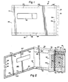
- FIGURE 1 is a front view of a return mailer assembly in accordance with the invention;
- FIGURE 2 is a perspective view of the return mailer assembly of claim 1, with the front sheet opened and the intermediate sheet peeled back to illustrate the layered construction of the return envelope portion of the mailer; and
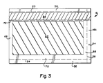
- FIGURE 3 is a front view of the rear sheet of the return mailer of the invention.
- Referring now to FIGURES 1-3 of the drawings, a multi-part
return mailer assembly 10 is illustrated which includes a first outer web orcover sheet 12, anintermediate web 14, and a secondouter web 16. In this return mailer assembly, the first and secondouter webs intermediate web 14 and the secondouter web 16 combine to form a return envelope portion. As such, theintermediate web 14 forms the front panel of the return envelope and the secondouter web 16 forms the rear panel of the return envelope. Upon receipt by the addressee, the firstouter web 12 is separable from the intermediate and second outer web as will be explained further hereinbelow. - The first outer web, or
cover sheet 12 is comprised of paper or other conventional stock, and is provided with a cut-out window portion 18 which, in conventional constructions, may be covered by a transparent flap or the like so as to display the name and address of the addressee. Other arrangements for displaying an address may be employed, and this feature does not constitute part of this invention. - An
upper perforation line 20 extends across the top of theweb 12, but spaced from the upper edge thereof, to provide aremovable stub 22. In a similar manner, alower perforation line 24 extends across the web spaced from the lower edge to provide alower removal stub 26. At the same time, a vertically oriented,third perforation line 28 defines aremovable side stub 30. As shown in phantom in FIGURE 1, a marginal feed strip 32 includingtractor feed holes 34 will typically have been utilized during the manufacture of the mailer in a continuous forms arrangement, but is subsequently removed prior to use. In this regard, it will be appreciated thatwebs lower edges 22′ and 26′. - The
perforation lines webs webs same reference numerals web 12, but with prime and double prime designations, respectively. - It will be appreciated that
webs outer webs side edge 36 such thatwebs shorter web 14 therebetween. In this arrangement, and to facilitate removal of theouter web 12 by the addressee,side edge 36 may be provided with a series of longitudinal perforations to define a tear line extending substantially parallel to theperforation line 28. - With specific reference to Fig 2, it may be seen that the inside surface 12a of the
outer web 12 is provided with lines ofadhesive 38, 40, 42, typically of the heat or pressure sensitive type, and which extend along theremovable stubs outer web 12 to theintermediate web 14 along alignedremovable stubs intermediate web 14 defined byperforation lines 20′, 24′, and 28′. In a similar manner, the secondouter web 16 has peripheral,movable stubs perforation lines 20˝, 24˝ and 28˝. The manner in which the intermediate and second outer webs are adhered along their respective removable stubs will be described further below. - The
intermediate web 14 is further characterized by anadditional perforation line 56 extending substantially parallel toperforation line 20 but vertically spaced therefrom to serve as a fold line for a returnenvelope sealing flap 58. - The improvement of this invention over conventional prior art return mailer assemblies, lies in the construction of
intermediate web 14 and/or the secondouter web 16 which combine to form the return envelope portion of the assembly. In a preferred embodiment, the stock of which theintermediate web 14 is formed is preferably of the dry gummed paper type, wherein a rewettable adhesive is provided over the entirety of one of the web surfaces. The adhesive is activated upon application of moisture, as is well understood by those of ordinary skill in the art. One particularly suitable dry gummed stock is that known as Nashua Davac™ produced by the Nashua Corporation of Nashua, New Hampshire. One advantage of this particular stock is that it can be printed on the gummed side, and this feature as already explained, is of considerable significance to this invention. - In the present invention, as already mentioned, the inner suface 14a of
web 14 is gummed, i.e., provided with a rewettable adhesive coating. Since surfaces 14a and 16a of thewebs webs - In this invention, advantage is taken of the gummed label stock printing feature to the extent that a predetermined area of the gummed surface 14a is provided with an ink pattern, and more specifically an ink pattern which serves as a moisture barrier to the gummed surface to which the pattern is applied.
- The moisture barrier is preferably a vegetable based ink, and preferably, one sold under the brand name NoTox™ manufactured by Colorcon, Inc. of West Point, Pennsylvania. This non-toxic and contaminant-free ink is suitable for wet or dry offset, letter press, heat-set or non-heat web offset, flexographic, gravure, pad printing, and silkscreen printing processes, thus providing a great deal of flexibility in the manufacture of the return mailer assembly. It will be understood by those of ordinary skill in the art that other vegetable based inks which have good moisture barrier characteristics may also be employed. Typically, of course, the application of the rewettable, gummed adhesive and the preselected printing patterns will be performed prior to the manufacture of the return mailer assembly, thereby enabling considerably higher mailer production speeds.
- Referring again to FIGURES 2 and 3, it may be seen that an ink pattern 60 has been applied to the surface 14a of
web 14 which forms one of the inner surfaces of the return envelope. In an alternative arrangement, acorresponding pattern 62 may be applied on the inner surface 16a ofweb 16 to provide increased moisture resistance. Athird pattern 64 is provided on surface 16a, over an area corresponding substantially to the returnenvelope sealing flap 58 formed onweb 14. As can be seen from the drawings, the pattern 60 (and 62 if utilized) will prevent sticking between substantially the entire surfaces 14a and 16a, corresponding to the inner surfaces of the envelope. However,peripheral portions webs removable stub portions web surface - The
pattern 64 prevents theenvelope flap portion 58 from sticking to theweb 16. However,flap 58 is not itself inked so that, when it is desired to use the return envelope, it may be moistened and secured toflap 16 when folded aboutline 58. - It will thus be understood that in the completed return mailer assembly, the first
outer web 12 is secured tointermediate web 14 about theadhesive lines 38, 40 and 42, while at the same time,web 14 and secondouter web 16 are adhesively secured in all areas of surface engagement with the exception of the inked pattern areas 60 and 64 (and, optionally, area 62). - As previously indicated, both
webs areas 60 and 64 remain as previously described. However, because of the increased adhesive composition present on the inner surfaces of the return envelope, it is preferred that inkedpattern 62 be applied to surface 16a as well to insure that surfaces 14a and 16a do not stick in other than the intended areas. - In use, the return mailer assembly is opened by removing the peripheral stub portions in sequential order. For example, the user may first tear the assembly along
perforation lines peripheral stub portions perforation lines stub portions lower perforation lines peripheral stub portions web 12 may then be peeled back and torn alongedge 36 leaving the return envelope formed bywebs - Typically, the inside surface of
web 12 will include billing or other account information and may have a separable return receipt portion which is returnable in the envelope formed bywebs - In order to use the return envelope, the user thereafter removes that portion of
web 16 covered by theink pattern 64 along aperforation line 72 so that the returnenvelope sealing flap 58 on theweb 14 may subsequently be folded alongline 56, moistened, and secured to the exterior surface of theweb 16 in a conventional manner. - The present invention also includes within its scope a process for forming a return mailer assembly of the type described hereinabove. The preferred process, in its broader aspects, includes the following steps:
- (a) providing first second and
third webs - (b) applying lines of adhesive 38, 40, 42 to at least three peripheral border portions of the first
outer web 12 for releasably attaching the firstouter web 12 to theintermediate web 14; - (c) coating at least the inner surface 14a of the
intermediate web 14 with a rewettable adhesive; and - (d) applying a moisture barrier in predetermined patterns 60 and 64 (and, optionally, 62) on surfaces 14a, 16a, respectively to prevent the inner surface portions of the return envelope from sticking.
- Alternatively, step (c) and (d) may also include the application of a rewettable adhesive to surface 16a and, preferably, the application of a moisture barrier in
area 62 as described hereinabove. - Accordingly, the present invention simplifies the production of return mailer assemblies by eliminating the previously required steps of applying heat or pressure sensitive adhesives (and heating in the case of heat sensitive adhesives) to selected areas of the inner surfaces of the return envelope portion of the assembly, thereby achieving substantially higher production speeds with no adverse affect on the overall quality of the mailer.
- It will further be appreciated that the utilization of dry gummed label stock is equally applicable to other envelope constructions and other types of business forms.
- While the invention has been described in connection with what is presently considered to be the most practical and preferred embodiment, it is to be understood that the invention is not to be limited to the disclosed embodiment, but on the contrary, is intended to cover various modifications and equivalent arrangements included within the spirit and scope fo the appended claims.
Claims (16)
a front panel having inner and outer surfaces;
a rear panel having inneer and outer surfaces;
at least one of said front and rear panels comprising dry-gummed paper stock wherein the outer surface of said at least one panel is ungummed and the inner surface of said at least one panel is gummed, and wherein said gummed inner surface of said at least one panel is partially coated with a water impervious composition in at least one preselected area to prevent sticking of said inner surfaces of said front and rear panels in said preselected area.
at least one of said intermediate and second outer webs are constructed of stock coated on an inner surface with a rewettable adhesive, and wherein at least one of said inner surfaces is provided with a moisture barrier in one or more predetermined areas to prevent sticking of the inner surfaces of said intermediate and second outer webs in said predetermined areas.
a front panel having inner and outer surfaces;
a rear panel having inner and outer surfaces;
at least one said front and rear panels comprising dry-gummed paper stock wherein the outer surface of said at least one panel is ungummed and the inner surface of said at least one panel is gummed, and wherein said gummed inner surface of said at least one panel is coated with a water impervious composition in at least one preselected area to prevent sticking of said inner surfaces of said front and rear panels in said preselected area.
Applications Claiming Priority (2)
| Application Number | Priority Date | Filing Date | Title |
|---|---|---|---|
| US156588 | 1988-02-17 | ||
| US07/156,588 US4779792A (en) | 1988-02-17 | 1988-02-17 | Return mailer assembly and related process |
Publications (3)
| Publication Number | Publication Date |
|---|---|
| EP0328811A2 true EP0328811A2 (en) | 1989-08-23 |
| EP0328811A3 EP0328811A3 (en) | 1990-09-19 |
| EP0328811B1 EP0328811B1 (en) | 1993-08-11 |
Family
ID=22560192
Family Applications (1)
| Application Number | Title | Priority Date | Filing Date |
|---|---|---|---|
| EP88309190A Expired - Lifetime EP0328811B1 (en) | 1988-02-17 | 1988-10-03 | Improved return mailer assembly and related process |
Country Status (4)
| Country | Link |
|---|---|
| US (1) | US4779792A (en) |
| EP (1) | EP0328811B1 (en) |
| CA (1) | CA1315747C (en) |
| PT (1) | PT88412B (en) |
Cited By (2)
| Publication number | Priority date | Publication date | Assignee | Title |
|---|---|---|---|---|
| GB2229962B (en) * | 1989-03-30 | 1992-11-11 | Moore Business Forms Inc | Improvements in return business forms assemblies |
| EP0538995A1 (en) * | 1991-10-22 | 1993-04-28 | Moore Business Forms, Inc. | Multiple part business form and related process |
Families Citing this family (13)
| Publication number | Priority date | Publication date | Assignee | Title |
|---|---|---|---|---|
| US4895297A (en) * | 1988-07-07 | 1990-01-23 | Moore Business Forms, Inc. | Business form set with closable envelope |
| US4969594A (en) * | 1989-06-16 | 1990-11-13 | Moore Business Forms, Inc. | Business forms mailer and related manufacturing process |
| US5039000A (en) * | 1990-02-22 | 1991-08-13 | Moore Business Forms, Inc. | Mailer with tear strip on outgoing and return envelopes |
| US5071399A (en) * | 1990-02-22 | 1991-12-10 | Moore Business Forms, Inc. | Method of making a mailer with tear strip on outgoing and return envelopes |
| US5011069A (en) * | 1990-06-26 | 1991-04-30 | Transkrit Corporation | Continuous mailer assembly |
| WO1993013950A1 (en) * | 1992-01-07 | 1993-07-22 | John Michael Woodbury | Self enveloping letter system |
| US5288014A (en) * | 1992-03-05 | 1994-02-22 | The Standard Register Company | Two-way mailer |
| US5238182A (en) * | 1992-03-31 | 1993-08-24 | Moore Business Forms, Inc. | Four part form from two sheets |
| US5248082A (en) * | 1992-06-15 | 1993-09-28 | Bedinghaus Business Communications, Inc. | Two-way mailer with pull tab |
| US5351425A (en) * | 1992-06-26 | 1994-10-04 | Apex Die & Box Company | Display device and processes for making and using the same |
| US6203068B1 (en) * | 1997-06-18 | 2001-03-20 | Glenn Petkovsek | Special service mailing assembly with label, tracking area and receipt and a method for preparing a mailpiece for delivery |
| US6131802A (en) * | 1998-04-30 | 2000-10-17 | Lombardo; Leo | Pressure seal form |
| US7721943B2 (en) | 2004-09-09 | 2010-05-25 | Moore Wallace North America, Inc. | Two way electronic media mailer |
Family Cites Families (16)
| Publication number | Priority date | Publication date | Assignee | Title |
|---|---|---|---|---|
| US2395419A (en) * | 1943-05-29 | 1946-02-26 | Du Pont | Pressure sensitive products |
| US2478070A (en) * | 1945-03-10 | 1949-08-02 | Harris Seybold Potter Co | Developing inks |
| US3261623A (en) * | 1964-11-23 | 1966-07-19 | Pak Well Paper Ind Inc | Envelope |
| US3411699A (en) * | 1966-06-24 | 1968-11-19 | Uarco Inc | Multiple use envelope assembly |
| US3523050A (en) * | 1967-03-10 | 1970-08-04 | Polaroid Corp | Process for preparing envelope structures |
| CA901533A (en) * | 1969-12-09 | 1972-05-30 | Dominion Envelope Company Limited | Two-way mailing envelope |
| US3681105A (en) * | 1970-04-22 | 1972-08-01 | Borden Inc | Pressure-sensitive adhesive web printed on back with transfer-proof ink |
| US3981435A (en) * | 1974-01-15 | 1976-09-21 | Johnsen Edward L | Continuous business form or the like adapted for subsequent processing into combination mailing envelopes and return envelopes having a common back ply panel |
| US3905545A (en) * | 1974-03-11 | 1975-09-16 | Uarco Inc | Continuous forms assembly |
| US3941308A (en) * | 1974-10-31 | 1976-03-02 | The Standard Register Company | Continuous mailer envelope assembly with inserts and method |
| US4055294A (en) * | 1975-12-11 | 1977-10-25 | Traise John E | Combined mailer and return envelope assembly |
| US4095695A (en) * | 1977-04-18 | 1978-06-20 | Wallace Business Forms, Inc. | Stuffed sealed envelope assembly and method of making |
| US4310117A (en) * | 1979-10-03 | 1982-01-12 | Moore Business Forms, Inc. | Envelope |
| NL8501397A (en) * | 1985-05-14 | 1986-12-01 | Lijnco Speciaaldrukkerij | ENVELOPE AND COURSE, CONSISTING OF CONNECTED ENVELOPES. |
| DE3543136A1 (en) * | 1985-12-06 | 1987-06-11 | Wegener August Awa Couvert | ENVELOPE, IN PARTICULAR FOR MACHINE CONVERTING |
| US4669652A (en) * | 1986-07-31 | 1987-06-02 | Sylvain Seguin | Two-way mailing envelope |
-
1988
- 1988-02-17 US US07/156,588 patent/US4779792A/en not_active Expired - Fee Related
- 1988-09-02 PT PT88412A patent/PT88412B/en not_active IP Right Cessation
- 1988-09-22 CA CA000578091A patent/CA1315747C/en not_active Expired - Fee Related
- 1988-10-03 EP EP88309190A patent/EP0328811B1/en not_active Expired - Lifetime
Cited By (2)
| Publication number | Priority date | Publication date | Assignee | Title |
|---|---|---|---|---|
| GB2229962B (en) * | 1989-03-30 | 1992-11-11 | Moore Business Forms Inc | Improvements in return business forms assemblies |
| EP0538995A1 (en) * | 1991-10-22 | 1993-04-28 | Moore Business Forms, Inc. | Multiple part business form and related process |
Also Published As
| Publication number | Publication date |
|---|---|
| US4779792A (en) | 1988-10-25 |
| PT88412B (en) | 1993-12-31 |
| CA1315747C (en) | 1993-04-06 |
| EP0328811A3 (en) | 1990-09-19 |
| EP0328811B1 (en) | 1993-08-11 |
| PT88412A (en) | 1989-10-04 |
Similar Documents
| Publication | Publication Date | Title |
|---|---|---|
| US4055294A (en) | Combined mailer and return envelope assembly | |
| US4779792A (en) | Return mailer assembly and related process | |
| CA1308394C (en) | Windowed mailer with return envelope for remittance document, having return mail-to address exposed by removal of original mail-to label | |
| US4012268A (en) | Continuous business form or the like adapted for subsequent processing into original indicia bearing lottery tickets, envelopes or the like | |
| US5951054A (en) | Core release layer label constructions | |
| US3981435A (en) | Continuous business form or the like adapted for subsequent processing into combination mailing envelopes and return envelopes having a common back ply panel | |
| US4380315A (en) | Mailer | |
| US4524903A (en) | One-piece two-way mailer unit | |
| MXPA96005101A (en) | Postal piece of seal by pressure folded e | |
| US5110043A (en) | Return mailer without fly sheet | |
| US5421620A (en) | Eccentric C-fold envelope with inserts for booklets and return mailers | |
| JPH0379263B2 (en) | ||
| EP0368509B1 (en) | Multiple web business form stock and mailers | |
| US5607738A (en) | Multiple-part carbonless pressure seal business form assembly | |
| US4801074A (en) | Sealed letter | |
| US5375763A (en) | V-fold two-ply mailer | |
| CA1185933A (en) | Mailer construction | |
| GB1564423A (en) | Continuous envelope assemblies | |
| CA2085786A1 (en) | Bifold mailer with return envelope | |
| US5092514A (en) | Two-part or three-part continuous form | |
| JP2787486B2 (en) | Mail having peelable adhesive paper surface and method of manufacturing the same | |
| USRE35103E (en) | Two-part or three-part continuous form | |
| JP3666130B2 (en) | Postcard sheet and postcard creation method using it | |
| JP2001030663A (en) | Information communication body manufacturing method | |
| JPH0448147U (en) |
Legal Events
| Date | Code | Title | Description |
|---|---|---|---|
| PUAI | Public reference made under article 153(3) epc to a published international application that has entered the european phase |
Free format text: ORIGINAL CODE: 0009012 |
|
| AK | Designated contracting states |
Kind code of ref document: A2 Designated state(s): BE ES FR GB GR IT LU NL |
|
| PUAL | Search report despatched |
Free format text: ORIGINAL CODE: 0009013 |
|
| AK | Designated contracting states |
Kind code of ref document: A3 Designated state(s): BE ES FR GB GR IT LU NL |
|
| 17P | Request for examination filed |
Effective date: 19910218 |
|
| 17Q | First examination report despatched |
Effective date: 19921204 |
|
| GRAA | (expected) grant |
Free format text: ORIGINAL CODE: 0009210 |
|
| AK | Designated contracting states |
Kind code of ref document: B1 Designated state(s): BE ES FR GB GR IT LU NL |
|
| PG25 | Lapsed in a contracting state [announced via postgrant information from national office to epo] |
Ref country code: IT Free format text: LAPSE BECAUSE OF FAILURE TO SUBMIT A TRANSLATION OF THE DESCRIPTION OR TO PAY THE FEE WITHIN THE PRE;WARNING: LAPSES OF ITALIAN PATENTS WITH EFFECTIVE DATE BEFORE 2007 MAY HAVE OCCURRED AT ANY TIME BEFORE 2007. THE CORRECT EFFECTIVE DATE MAY BE DIFFERENT FROM THE ONE RECORDED.SCRIBED TIME-LIMIT Effective date: 19930811 Ref country code: ES Free format text: THE PATENT HAS BEEN ANNULLED BY A DECISION OF A NATIONAL AUTHORITY Effective date: 19930811 Ref country code: GR Free format text: LAPSE BECAUSE OF FAILURE TO SUBMIT A TRANSLATION OF THE DESCRIPTION OR TO PAY THE FEE WITHIN THE PRESCRIBED TIME-LIMIT Effective date: 19930811 Ref country code: BE Effective date: 19930811 |
|
| PG25 | Lapsed in a contracting state [announced via postgrant information from national office to epo] |
Ref country code: LU Free format text: LAPSE BECAUSE OF NON-PAYMENT OF DUE FEES Effective date: 19931031 |
|
| PGFP | Annual fee paid to national office [announced via postgrant information from national office to epo] |
Ref country code: NL Payment date: 19931031 Year of fee payment: 6 |
|
| ET | Fr: translation filed | ||
| PGFP | Annual fee paid to national office [announced via postgrant information from national office to epo] |
Ref country code: FR Payment date: 19940114 Year of fee payment: 6 |
|
| PGFP | Annual fee paid to national office [announced via postgrant information from national office to epo] |
Ref country code: GB Payment date: 19940118 Year of fee payment: 6 |
|
| PLBE | No opposition filed within time limit |
Free format text: ORIGINAL CODE: 0009261 |
|
| STAA | Information on the status of an ep patent application or granted ep patent |
Free format text: STATUS: NO OPPOSITION FILED WITHIN TIME LIMIT |
|
| 26N | No opposition filed | ||
| PG25 | Lapsed in a contracting state [announced via postgrant information from national office to epo] |
Ref country code: GB Effective date: 19941003 |
|
| PG25 | Lapsed in a contracting state [announced via postgrant information from national office to epo] |
Ref country code: NL Effective date: 19950501 |
|
| GBPC | Gb: european patent ceased through non-payment of renewal fee |
Effective date: 19941003 |
|
| NLV4 | Nl: lapsed or anulled due to non-payment of the annual fee | ||
| PG25 | Lapsed in a contracting state [announced via postgrant information from national office to epo] |
Ref country code: FR Effective date: 19950630 |
|
| REG | Reference to a national code |
Ref country code: FR Ref legal event code: ST |