EP0328779A2 - Sprungvorhersagevorrichtung für Komputerbefehle - Google Patents
Sprungvorhersagevorrichtung für Komputerbefehle Download PDFInfo
- Publication number
- EP0328779A2 EP0328779A2 EP88121547A EP88121547A EP0328779A2 EP 0328779 A2 EP0328779 A2 EP 0328779A2 EP 88121547 A EP88121547 A EP 88121547A EP 88121547 A EP88121547 A EP 88121547A EP 0328779 A2 EP0328779 A2 EP 0328779A2
- Authority
- EP
- European Patent Office
- Prior art keywords
- operand
- circuit means
- bit
- operands
- sum
- Prior art date
- Legal status (The legal status is an assumption and is not a legal conclusion. Google has not performed a legal analysis and makes no representation as to the accuracy of the status listed.)
- Withdrawn
Links
Images


Classifications
-
- G—PHYSICS
- G06—COMPUTING OR CALCULATING; COUNTING
- G06F—ELECTRIC DIGITAL DATA PROCESSING
- G06F9/00—Arrangements for program control, e.g. control units
- G06F9/06—Arrangements for program control, e.g. control units using stored programs, i.e. using an internal store of processing equipment to receive or retain programs
- G06F9/30—Arrangements for executing machine instructions, e.g. instruction decode
- G06F9/38—Concurrent instruction execution, e.g. pipeline or look ahead
- G06F9/3836—Instruction issuing, e.g. dynamic instruction scheduling or out of order instruction execution
- G06F9/3842—Speculative instruction execution
- G06F9/3844—Speculative instruction execution using dynamic branch prediction, e.g. using branch history tables
Definitions
- the present invention relates to the field of digital computers. More specifically, the present invention relates to the prediction of branching conditions for branching instructions executed by such a computer.
- the performance of a computer is greatly affected by the speed at which a branch instruction may be executed.
- computers execute multipath instruction sequences, with a path selected at a node represented by a branch instruction. Path selection is based upon execution of the branch instruction.
- Branch instruction execution requires the comparison of operands within the computer to determine whether a branch is taken or not. The sooner the outcome can be determined, the better the performance of the computer.
- a key element in determining whether a branch is to be taken or not is the comparison of operands on which the branch condition is contingent. Although the comparison of operands is a key element in other instruction types, branching is an important aspect of computer operation.
- a branch instruction operation is performed by the arithmetic/logic unit of a computer according to a known procedure.
- a branching instruction includes three fields. One field indicates a register, R3, which contains an increment. A second field indicates a register, R1, containing the current value of an index. A third field indicates a branch destination.
- the instruction is executed by algebraically combining the increment in R3 with the current value in R1, and comparing the incremented current value against a compare value. If the R3 field is even, an even-odd pair of registers (R3 and R3+1) is understood, containing the increment and compare values, respectively. If the R3 field is odd, R3 contains both the increment and the compare value.
- a branch to the branch destination is taken when the incremented current value is higher than the final value. In another, the branch occurs when the incremented current value is less than or equal to the compare value.
- the instructions may be classified into two broad categories.
- the first category of instructions includes those where the branch is taken when the incremented current value is greater than the compare value.
- the other category of instructions are where the branch is taken when the incremented current value is less than or equal to the compare value.
- the traditional method of determining the outcome of the two categories of branch instructions is to perform the increment operation, subtract the compared value from the increment result, and determine if the result of the subtraction is greater than, less than, or equal to zero. Depending on this determination, the branch is either taken or not. Therefore, in the prior art, determining whether the branch will be taken must wait until the increment and compare operations are completed. In most machines, these operations require two machine cycles. It is an objective of the present invention to reduce the time required for the determination of a branch condition, or other condition depending upon a similar comparison of operands.
- the described embodiment of the present invention provide for the determination, in a computer of the validity of a branch condition, which is then used by the computer to perform other operations such as branching.
- the prediction is based upon three operands: a first operand, the current value, an increment operand, and the final value operand. Because the invention determines a condition directly from these three operands, the outcome may be computed concurrently with incrementation of the first operand during execution of the branching instruction. In addition, the requirement for subtraction of the comparison value from the increment result is eliminated because the comparison result is not required to perform the prediction. Because the prediction is made by the invention, branch determination may be made in one machine cycle.
- the present invention includes a combinational logic circuit which determines whether the combination of operands provided to the logic circuit will result in a branch, or not.
- the combinational circuit is based upon six comparisons. If the sign bit of the SUM of the current value operand, Q, and the increment operand R indicates a positive number, and the sign bit of the compare value operand, B, indicates a negative number, the SUM of Q and R, hereafter called A, is always greater than B; if the sign bit of both A and B indicate positive numbers and the sign bit of the the combination of B subtracted from the SUM of Q and R, hereafter called SUM0, indicates a positive number, A is greater than or equal to B.
- A is less than B. If the sign bit of both A and B indicate negative numbers and SUM0 indicates a positive number, A is greater than or equal to B. If the sign of both A and B indicate negative numbers and SUM0 indicates a negative number, A is less than B. If the sign bit of A indicates a negative number and the sign bit of B indicates a positive number, then A is less than B.
- the operational context of the invention is exemplified by a computer system which executes branching instructions of a type described in the background above.
- the computer system includes an arithmetic/logic unit for performing arithmetic and logical operations which support instruction execution.
- the invention operates in response to the three operands upon which execution of the branching instructions are based, namely: the current value operand, Q, the increment operand, R, and the compare value operand, B.
- the operands, Q, R, and B are assumed to be 32-bit digital words, each consisting of bits 0-31, with bit 0 of each operand being the most significant bit (MSB), and 31 being the least significant bit (LSB).
- the invention operates algebraically on these operands to produce intermediate values, Px and Py, each consisting also of 32 bits numbered in descending order of significance from 0-31.
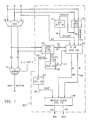
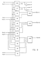
- Fig. 1 is a block schematic diagram showing the structure and operation of the present invention.
- an adder circuit including a conventional carry-save adder 10 and a conventional adder 11, which operate to combine the operands Q, R and B using carry-save adder techniques.
- B the compare value operand
- B is subtracted from the combination of Q and R by the well-known technique of two's complements addition.
- B is provided to the carry-save adder 10 in one's complement form (B′).
- B′ the two's complement of B is obtained by adding a one to the one's complement value. The one is added as a "hot" one to intermediate values Px and Py combined in the conventional adder 11.
- the invention includes a branch prediction circuit 20, having a first auxillary (AUX1) circuit block 13 which receives Q and R, and produces intermediate results denoted as Ha0 and Ma0 on signal path 14, and intermediate products Ta Ga and Sa on signal path 15.
- the circuit block 13 is illustrated in greater detail in Figures 3-5.
- An intermediate block 17 (Sa1) receives the signals on path 15 and produces a complementary set of intermediate values Sa1, and Sa1′ on signal path 19.
- the circuit block 17 is shown in detail in Figure 6.
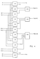
- a second auxillary block (AUX2) 21 receives intermediate values Pxi and Pyi output by the carry-save adder 10 and, in response, produces first intermediate complementary signals H0 and H0′ and second intermediate complementary signals T1 and T1′ on signal path 22.
- the block 21 produces intermediate values T, G, and S24 on signal path 23.
- the auxillary block 21 provides intermediate values H0-H30 and passes through intermediate value Px31.
- the circuit block 21 is illustrated in greater detail in Figs. 8-11.
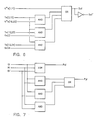
- An intermediate value block 27 (S1, illustrated in Fig. 12) produces a pair of complementary signals S1 and S1′ on signal line 28 in response to the signals on signal line 23.
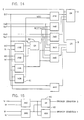
- An intermediate product block 29 (illustrated in Fig. 13) receives the signals on signal path 25 and produces an intermediate value E on signal path 31.
- a circuit block 40 provides two signals -- BRANCH CATEGORY 1 (BC1) and BRANCH CATEGORY 2 (BC2) -- on signal lines 43 and 45, respectively, in response to signals on signal paths 28, 35, and 37.
- BC1 BRANCH CATEGORY 1
- BC2 BRANCH CATEGORY 2
- the apparatus of the invention will detect and indicate two branching condition categories: BRANCH CATEGORY 1, and BRANCH CATEGORY 2, each indicated by a respective output of the block 40 in Fig. 1.
- BRANCH CATEGORY 1 covers the category of branch instructions in which a branch is taken when the incremented current value is greater than the compare value
- BRANCH CATEGORY 2 indicates prediction of the outcome of the operation conducted by those branching instructions in which the incremented current value is less than or equal to the compare value.
- the BRANCH CATEGORY 2 signal indicates the condition of the expression (A ⁇ B).
- SUM0 (M(0) ⁇ S(1))
- M(0) H(0) V T(1)
- M(0) is a signal developed by an exclusive-OR (XOR) gate 50 contained in the circuit block 33, as shown in Fig. 14
- H(0) Px(0) V Py(1)
- H(0) is a signal developed by an XOR gate 52 included in the AUX2 circuit 21 as shown in Fig.
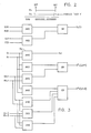
- Px(i) and Py(i) are computed by the carry-save-adder 10 according to the following equations, which are represented schematically in Fig. 7.
- Ha(0) Q(0) V R(0) Ha(0) is generated in the circuit block 13 by the XOR gate 65 illustrated in Fig. 4;
- Sa(1) G*a(1,m)
- G*a(1,m) Ga(1)
- G*a(1,m) is generated in the circuit block 13 by an OR gate such as the gate 67 in Fig.
- Ta(2,m+1) Ta(2) ⁇ Ta(3) ⁇ Ta(4) ⁇ Ta(5) ⁇ ... ⁇ Tam ⁇ Tam+1
- Ta(2,m+1) is generated in circuit block 13 by an AND gate such as the gate 69 in Fig. 5;
- Ta(1) Q(1)
- E Px(31) ⁇ H(0) ⁇ H(1) ⁇ H(2) ⁇ ... ⁇ H(30)
- E is generated by the E circuit block 29 through the AND gate 75 in Fig. 13, which implements the expression for E given above.
- equation (3) (with the expression for E substituted into it) predicts the outcome of the category 2 instructions from the Q, R and B inputs directly.
- G*(1,m) G(1)
- (T(2,m-1) ⁇ G(m)) T(2,m+1) T(2) ⁇ T(3) ⁇ T(4) ⁇ T(5) ⁇ ... ⁇ T(m) ⁇ T(m+1)
- G(1) Px(1) ⁇ Py(2)
- T(1) Px(1)
- G*a(1,m) Ga(1)
- (Ta(2,m-1) ⁇ G(m)) Ta(2,m+1) Ta(2) ⁇ Ta(3) ⁇ Ta(4) ⁇ Ta(5) ⁇ ... ⁇ Tam ⁇ Tam+(1)
- prediction circuit 20 determines the outcome of the branching condition using fewer gate levels than a two-step addition system thereby speeding the branch prediction instruction.
- the described embodiments of the present invention provide logic circuitry to determine the validity of a condition which is then used by a computer to perform other operations such as branching.
- the prediction uses a first operand, an increment operand, and a compare operand as input signals. Because the invention determines a condition directly from the input operands, the outcome may be computed at the same time as the first operand is being incremented. In addition, no subtraction of the comparison value from the increment result must be performed because the comparison result is not required to perform the prediction. Because of this direct computation, the prediction result may be determined in one machine cycle.
- the present invention provides a combinational logic circuit which determines whether the combination of operands provided to the logic circuit indicates the condition whether a branch is to occur or not.
- the combinational circuit is based upon six comparisons.
- the sign bit of a SUM of an operand Q and the increment operand R indicates a positive number
- the sign bit of the comparison operand B indicates a negative number
- the SUM of Q and R is always greater than B
- the sign bit of both A and B indicate positive numbers
- the sign bit of the combination of B subtracted from the SUM of Q and R hereafter called SUM0
- A is greater than or equal to B: if the sign bit of both A and B indicate positive numbers and SUM0 indicates a negative number, A is less than B; if the sign bit of both A and B indicate negative numbers and SUM0 indicates a positive number, A is greater than or equal to B; if the sign of both A and B indicate negative numbers and SUM0 indicates a negative number, A is less than B; if the sign of both A and B indicate negative numbers and SUM0 indicates a negative number, A is less than B; if the sign of A indicates a negative number and the sign of B indicates a positive number, then A is less than B.
Landscapes
- Engineering & Computer Science (AREA)
- Software Systems (AREA)
- Theoretical Computer Science (AREA)
- Physics & Mathematics (AREA)
- General Engineering & Computer Science (AREA)
- General Physics & Mathematics (AREA)
- Advance Control (AREA)
- Executing Machine-Instructions (AREA)
Applications Claiming Priority (2)
| Application Number | Priority Date | Filing Date | Title |
|---|---|---|---|
| US07/157,474 US4914579A (en) | 1988-02-17 | 1988-02-17 | Apparatus for branch prediction for computer instructions |
| US157474 | 1988-02-17 |
Publications (2)
| Publication Number | Publication Date |
|---|---|
| EP0328779A2 true EP0328779A2 (de) | 1989-08-23 |
| EP0328779A3 EP0328779A3 (de) | 1992-01-02 |
Family
ID=22563891
Family Applications (1)
| Application Number | Title | Priority Date | Filing Date |
|---|---|---|---|
| EP19880121547 Withdrawn EP0328779A3 (de) | 1988-02-17 | 1988-12-23 | Sprungvorhersagevorrichtung für Komputerbefehle |
Country Status (3)
| Country | Link |
|---|---|
| US (1) | US4914579A (de) |
| EP (1) | EP0328779A3 (de) |
| JP (1) | JPH028936A (de) |
Families Citing this family (5)
| Publication number | Priority date | Publication date | Assignee | Title |
|---|---|---|---|---|
| US5349671A (en) * | 1989-03-23 | 1994-09-20 | Matsushita Electric Industrial Co., Ltd. | Microprocessor system generating instruction fetch addresses at high speed |
| US5434986A (en) * | 1992-01-09 | 1995-07-18 | Unisys Corporation | Interdependency control of pipelined instruction processor using comparing result of two index registers of skip instruction and next sequential instruction |
| US5905881A (en) * | 1995-11-30 | 1999-05-18 | Unisys Corporation | Delayed state writes for an instruction processor |
| US5867699A (en) * | 1996-07-25 | 1999-02-02 | Unisys Corporation | Instruction flow control for an instruction processor |
| US5974538A (en) * | 1997-02-21 | 1999-10-26 | Wilmot, Ii; Richard Byron | Method and apparatus for annotating operands in a computer system with source instruction identifiers |
Family Cites Families (12)
| Publication number | Priority date | Publication date | Assignee | Title |
|---|---|---|---|---|
| US3418638A (en) * | 1966-09-21 | 1968-12-24 | Ibm | Instruction processing unit for program branches |
| US3551895A (en) * | 1968-01-15 | 1970-12-29 | Ibm | Look-ahead branch detection system |
| FR2056229A5 (de) * | 1969-07-31 | 1971-05-14 | Ibm | |
| US4062058A (en) * | 1976-02-13 | 1977-12-06 | The United States Of America As Represented By The Secretary Of The Navy | Next address subprocessor |
| US4200927A (en) * | 1978-01-03 | 1980-04-29 | International Business Machines Corporation | Multi-instruction stream branch processing mechanism |
| US4224680A (en) * | 1978-06-05 | 1980-09-23 | Fujitsu Limited | Parity prediction circuit for adder/counter |
| US4320464A (en) * | 1980-05-05 | 1982-03-16 | Control Data Corporation | Binary divider with carry-save adders |
| US4430706A (en) * | 1980-10-27 | 1984-02-07 | Burroughs Corporation | Branch prediction apparatus and method for a data processing system |
| US4439827A (en) * | 1981-12-28 | 1984-03-27 | Raytheon Company | Dual fetch microsequencer |
| JPS6051948A (ja) * | 1983-08-31 | 1985-03-23 | Hitachi Ltd | 情報処理装置 |
| JPS60107141A (ja) * | 1983-11-16 | 1985-06-12 | Fujitsu Ltd | プランチ制御方式 |
| US4837681A (en) * | 1986-03-13 | 1989-06-06 | Tandem Computers Incorporated | Instruction sequencer branch mechanism |
-
1988
- 1988-02-17 US US07/157,474 patent/US4914579A/en not_active Expired - Fee Related
- 1988-12-19 JP JP63318659A patent/JPH028936A/ja active Pending
- 1988-12-23 EP EP19880121547 patent/EP0328779A3/de not_active Withdrawn
Also Published As
| Publication number | Publication date |
|---|---|
| US4914579A (en) | 1990-04-03 |
| JPH028936A (ja) | 1990-01-12 |
| EP0328779A3 (de) | 1992-01-02 |
Similar Documents
| Publication | Publication Date | Title |
|---|---|---|
| US5530663A (en) | Floating point unit for calculating a compound instruction A+B×C in two cycles | |
| EP0483864B1 (de) | Hardware-Anordnung zur Addition und Subtraktion von Gleitkommazahlen | |
| US4999803A (en) | Floating point arithmetic system and method | |
| JPH0542011B2 (de) | ||
| US5299319A (en) | High performance interlock collapsing SCISM ALU apparatus | |
| CA1324217C (en) | Pipelined floating point adder for digital computer | |
| US4001570A (en) | Arithmetic unit for a digital data processor | |
| US3814925A (en) | Dual output adder and method of addition for concurrently forming the differences a{31 b and b{31 a | |
| US5301341A (en) | Overflow determination for three-operand alus in a scalable compound instruction set machine which compounds two arithmetic instructions | |
| US3825895A (en) | Operand comparator | |
| EP0295788B1 (de) | Einrichtung und Verfahren für eine erweiterte Arithmetik-Logik-Einheit zur Beschleunigung der ausgewählten Operationen | |
| US3752394A (en) | Modular arithmetic and logic unit | |
| US6499044B1 (en) | Leading zero/one anticipator for floating point | |
| US4947359A (en) | Apparatus and method for prediction of zero arithmetic/logic results | |
| US5831884A (en) | Apparatus for performing arithmetic operation of floating point numbers capable of improving speed of operation by performing canceling prediction operation in parallel | |
| US4914579A (en) | Apparatus for branch prediction for computer instructions | |
| US5867413A (en) | Fast method of floating-point multiplication and accumulation | |
| US6813628B2 (en) | Method and apparatus for performing equality comparison in redundant form arithmetic | |
| EP0643352A1 (de) | Selbstprüfender komplementärer Addierer | |
| JPH0346024A (ja) | 浮動小数点演算器 | |
| EP0520298A2 (de) | Arithmetische Schaltung | |
| US5644521A (en) | Comparator scheme | |
| US20020178202A1 (en) | Floating point multiplier for delimited operands | |
| EP0704793B1 (de) | Verfahren und Schaltungsanordnung zum Vergleichen der Summe zweier Zahlen mit einer dritten Zahl | |
| EP0626638A1 (de) | Einserkomplementaddierer und Betriebsverfahren |
Legal Events
| Date | Code | Title | Description |
|---|---|---|---|
| PUAI | Public reference made under article 153(3) epc to a published international application that has entered the european phase |
Free format text: ORIGINAL CODE: 0009012 |
|
| AK | Designated contracting states |
Kind code of ref document: A2 Designated state(s): DE FR GB |
|
| 17P | Request for examination filed |
Effective date: 19891214 |
|
| PUAL | Search report despatched |
Free format text: ORIGINAL CODE: 0009013 |
|
| AK | Designated contracting states |
Kind code of ref document: A3 Designated state(s): DE FR GB |
|
| STAA | Information on the status of an ep patent application or granted ep patent |
Free format text: STATUS: THE APPLICATION IS DEEMED TO BE WITHDRAWN |
|
| 18D | Application deemed to be withdrawn |
Effective date: 19940701 |