EP0328443B1 - Verfahren zum Digitalisieren der Oberfläche eines dreidimensionalen Gegenstandes und Aufnahmevorrichtung zur Anwendung dieses Verfahrens - Google Patents
Verfahren zum Digitalisieren der Oberfläche eines dreidimensionalen Gegenstandes und Aufnahmevorrichtung zur Anwendung dieses Verfahrens Download PDFInfo
- Publication number
- EP0328443B1 EP0328443B1 EP89400325A EP89400325A EP0328443B1 EP 0328443 B1 EP0328443 B1 EP 0328443B1 EP 89400325 A EP89400325 A EP 89400325A EP 89400325 A EP89400325 A EP 89400325A EP 0328443 B1 EP0328443 B1 EP 0328443B1
- Authority
- EP
- European Patent Office
- Prior art keywords
- axis
- rotation
- video
- angle
- viewpoints
- Prior art date
- Legal status (The legal status is an assumption and is not a legal conclusion. Google has not performed a legal analysis and makes no representation as to the accuracy of the status listed.)
- Expired - Lifetime
Links
Images


Classifications
-
- A—HUMAN NECESSITIES
- A61—MEDICAL OR VETERINARY SCIENCE; HYGIENE
- A61B—DIAGNOSIS; SURGERY; IDENTIFICATION
- A61B5/00—Measuring for diagnostic purposes; Identification of persons
- A61B5/0059—Measuring for diagnostic purposes; Identification of persons using light, e.g. diagnosis by transillumination, diascopy, fluorescence
- A61B5/0062—Arrangements for scanning
- A61B5/0064—Body surface scanning
-
- A—HUMAN NECESSITIES
- A61—MEDICAL OR VETERINARY SCIENCE; HYGIENE
- A61B—DIAGNOSIS; SURGERY; IDENTIFICATION
- A61B5/00—Measuring for diagnostic purposes; Identification of persons
- A61B5/103—Measuring devices for testing the shape, pattern, colour, size or movement of the body or parts thereof, for diagnostic purposes
- A61B5/107—Measuring physical dimensions, e.g. size of the entire body or parts thereof
- A61B5/1077—Measuring of profiles
-
- G—PHYSICS
- G01—MEASURING; TESTING
- G01B—MEASURING LENGTH, THICKNESS OR SIMILAR LINEAR DIMENSIONS; MEASURING ANGLES; MEASURING AREAS; MEASURING IRREGULARITIES OF SURFACES OR CONTOURS
- G01B11/00—Measuring arrangements characterised by the use of optical techniques
- G01B11/24—Measuring arrangements characterised by the use of optical techniques for measuring contours or curvatures
- G01B11/25—Measuring arrangements characterised by the use of optical techniques for measuring contours or curvatures by projecting a pattern, e.g. one or more lines, moiré fringes on the object
- G01B11/2518—Projection by scanning of the object
-
- G—PHYSICS
- G05—CONTROLLING; REGULATING
- G05B—CONTROL OR REGULATING SYSTEMS IN GENERAL; FUNCTIONAL ELEMENTS OF SUCH SYSTEMS; MONITORING OR TESTING ARRANGEMENTS FOR SUCH SYSTEMS OR ELEMENTS
- G05B19/00—Program-control systems
- G05B19/02—Program-control systems electric
- G05B19/42—Recording and playback systems, i.e. in which the program is recorded from a cycle of operations, e.g. the cycle of operations being manually controlled, after which this record is played back on the same machine
- G05B19/4202—Recording and playback systems, i.e. in which the program is recorded from a cycle of operations, e.g. the cycle of operations being manually controlled, after which this record is played back on the same machine preparation of the program medium using a drawing, a model
- G05B19/4207—Recording and playback systems, i.e. in which the program is recorded from a cycle of operations, e.g. the cycle of operations being manually controlled, after which this record is played back on the same machine preparation of the program medium using a drawing, a model in which a model is traced or scanned and corresponding data recorded
Definitions
- the invention relates to a method of digitizing the surface of a three-dimensional object (or subject) making it possible to generate digital data representative of the coordinates of the points of this surface in a three-dimensional frame of reference. It relates to a method of acquiring the relief of the object from structured lighting with lamellar beams, in particular lasers, and from a video capture device. It extends to a recording device adapted to deliver a video signal representative of the surface of the object, this signal being able either to be digitized in real time locally or after remote transmission to provide the aforementioned digital signal, or to be recorded and digitized later. at the time of its operation.
- the invention aims very particularly, but not exclusively, to carry out the survey of a human head or bust, in particular with a view to reproduction by machining.
- each activated pixel of the video signal is directly representative of the coordinates of a point of the object in the light trace (two-dimensional coordinates) and the processing is confined to a digital coding of these pixels activated and their memorization associated with information relating to the scanning movement of the surface (which are representative of the third coordinate).
- the invention relates to an improved digitization process which makes it possible to completely dispense with the hardware geometry of the system and to avoid determining the coordinates sought by trigonometric calculations.
- the aim of the digitization process aimed by the invention is to generate a set of digital data representative of the coordinates of the points of the surface of a three-dimensional object (or subject) in a three-dimensional frame of reference.
- This process is of the type set out in the preamble of claim 1, which corresponds to the teachings of the aforementioned EP-A-0 163 076
- the method according to the present invention is characterized by the specific calibration steps set out in the preamble of claim 1
- the parameter measurements are reduced to the simple definition (once 'for all) of a calibration target, and to its digitization by the method of the invention; no physical measurement of geometric parameters (distance, angle) is required on the system, which in practice represents a considerable advantage.
- the invention extends to an apparatus for three-dimensional surveying of the surface of an object, according to claim 16.
- the reading device shown by way of example in FIGS. 1 to 6 is intended for reading a human head, in particular with a view to its reproduction by machine tool with digital control; this device comprises a bracket 1 held by a base 2 in order to overhang a subject S seated on a seat 3.
- the bracket 1 constituted by a closed casing contains an electric motor 4 associated with a reducer 5.
- This reducer is coupled to a transmission system 6, in the example with pulleys and toothed belt, in order to drive a vertical output shaft 7 which defines an axis of rotation Z contained in the median plane M and passing through the vertical of the seat 3.
- an angular position sensor 8 is coupled to the shaft of the electric motor in order to deliver at all times a signal representative of the angular position of the motor shaft relative to a fixed mark and therefore representative the angular position ⁇ of the output shaft 7 relative to the subject S.
- This sensor is in particular constituted by an electric pulse generator of frequency proportional to the speed of rotation (tone wheel mounted on the motor shaft and Inductive sensor). It should be noted that this sensor can, if necessary, be deleted in the case of a constant speed of rotation, the angular position ⁇ then being deduced from the elapsed time, directly measured by the frequency of the scrolling of the video images.
- the vertical shaft 7 carries a rotating support 9 having a vertical front extension 9a and a horizontal upper extension 9b.
- a centering member 10 is fixed to the upper extension 9b in a vertical position, coaxial with the shaft 7; this body is intended to come to rest above the subject's head, thanks to a rubber pad 10a mounted to rotate freely. The subject can thus center himself by leaning against this pad in order to remain perfectly still during the reading.
- the member 10 is constituted by a tube, along the length of which is inserted an openwork profile 10b in order to clear the optical path between a camera 11 fixed under the upper extension 9b and a set of mirrors fixed on the frontal extension 9a.
- the camera 11 is thus fixed opposite the mirrors with respect to the subject, in the median plane M of the rotating assembly carried by the support 9. (The camera 11 is inverted so as to produce an image at the location if a control monitor is connected to it).
- the mirrors 12c1 and 13c1 are arranged on one side of the median plane M with an edge flush with the latter (in the example on the right side seen from the camera), so that the field of view reflected by these mirrors corresponds to the half space E-located on the right side of the median plane M.
- the mirrors 14c2 and 15c2 are arranged on the other side (left) so that the field of view defined by these mirrors corresponds to the half-space E2 located on the left side of the median plane M.
- the fields attached to the two viewpoints C1 and C2 are disjoint and correspond to two contiguous half-images in the camera 11.
- the mirrors 12c1 and 13c1 are geometrically arranged so as to generate a point of view C1 when diving from the subject; for this purpose, the angle of view (angle c1 formed by the optical axis and by the axis of rotation Z) is less than 90 ° and in particular of the order of 65 °.
- the mirrors 14c2 and 15c2 are geometrically arranged so as to generate a point of view C2 in counter-diving, the angle of view c2 being greater than 90 ° and in particular of the order of 115 °.
- these mirrors are arranged so that the lengths of the optical paths, left and right, are similar to allow a single focus.
- extension 9a carries on either side of the median plane M two helium / neon laser devices with cylindrical lenses 1611 and 1712, arranged head to tail; these laser devices are known in themselves and each provide a lamellar laser beam. As illustrated in FIG.
- L las and L en the fictitious laser sources obtained by assuming each beam directly from a point; in practice, the real laser source of each device is offset by the presence of an optical system 35, 36 contained in these laser devices with lamellar beam; however, in the characteristic geometry of the invention, it is the positions of these fictitious sources L1 and L2 which are to be considered (as well as for the fictitious points of view C1 and C2 in the case of the video device).
- the camera 11 is equipped with an interference filter tuned to the wavelength of the lasers, so as to make it specifically substantially at this wavelength and to overcome the problems of ambient lighting.
- the laser device 1611 located on the right of the side of the point of view C1 (while diving) illuminates the subject while diving at an angle l1 (relative to the axis of rotation Z) substantially equal to the angle of view c1.
- the other device located on the left side of the point of view C2 (in counter-diving) illuminates the subject in counter-diving at an angle l2 substantially equal to the angle of view c2.
- the two devices 1611 and 1712 are arranged, head to tail, symmetrically with respect to the median plane M so that the corresponding light beams are contained in vertical planes P1 and P2 passing through the axis of rotation Z and forming angles of parallaxes p1, p2, in the example substantially equal to 30 ° on either side of the plane M.
- the beams thus form two light traces on the subject, located on either side of the median plane M.
- a conventional rotary joint is included in the output shaft 7 in order to allow the electrical supply of the camera 11 and of the laser devices 1611 and 1712 and the transfer of the video signal from the camera.
- the geometric arrangement of the points of view C1, C2 and sources L1 and L2 is symbolized in Figures 7 and 8 in order to make it clearer.
- the reference XYZ is a fixed reference linked to the subject and the reference xyz a mobile reference linked to the rotating support 9, these reference points being assumed to be coincident at the initial instant and forming an angle ⁇ , at an instant t of the rotation corresponding to a take given image.
- FIG. 9 illustrates an example of a processing chain for the video signal coming from the camera 11, and angular position information coming from the sensor 8.
- the video signal is recorded by means of a video recorder 18 on a magnetic tape.
- traditional symbolized in 19
- the angular position signal constituted by an audio frequency proportional to the speed being recorded on the SON track of this magnetic tape 19.
- This recording carried out directly downstream of the camera 11 and of the sensor 8 makes it possible to eliminate any processing at the level of the reading device and therefore to reduce the price of this device which is made available to a commercial network in contact with the public.
- the strips 19 are centralized in one or more specialized centers equipped, on the one hand, with a UT processing unit as described below, on the other hand, numerically controlled machine tools, capable of operating the base digital data obtained to make the reproductions in relief.
- each band 19 is read on a video recorder 20 which delivers the signals to an analog / digital converter 21.
- this converter codes on each line (v1, v2 %) the positions of the activated pixels ( u1, u2 %) and writes them to a storage memory 22.
- This coding can be carried out by writing sequentially in the memory cells, the code of the position of each pixel on its line (u1, u2 %), the cell address being representative of the line number (v1, v2 ).
- the converter 21 includes a counter for digitizing the position signal of the SON track, this digitized signal (representative of ⁇ ) being stored at the header of each image.
- the system can operate in the absence of a position signal; the aforementioned counter then records the "frame synchronization top" in order to identify each image by its time position.
- the digitized positions (u1, v1; u2, v2 ...) stored, for each image, in the memory 22 are delivered to a track separator 23 which realizes a partition of these into two buffer files 24 and 25, each containing the digitized positions of the traces formed by a laser (L1 or L2) and the corresponding angular positions ⁇ .
- This partition illustrated in FIG. 10, is performed by comparing for each line (v1, v2 ...) the values of the digitized positions (u1, u2 ...) with the median value (u m ) corresponding to the position of the axis of rotation Z in the image.
- the digitized positions and the header ⁇ are stored in the buffer file 24; in the case of a higher value, they are stored in the buffer file 25.
- information representative of the geometry of the video device / laser beam assembly is stored in a memory 26 and delivered to a microcomputer 27; in the example, this information is representative of the parallaxes of the beams p1, p2, and of the angles of diving and of plunging c1 and c2 from the two points of view and are defined by prior measurements of angles and of distance.
- this geometry information associated with the angular position information ⁇ allows the microcomputer 27 to calculate (by conventional trigonometric calculations) information, said to be specific, attached to each laser beam and to the corresponding point of view for the image considered.
- This information characterizes the trace which is formed by said beam and which is observed from this point of view; they are associated with the digitized positions corresponding to this trace in order to provide the third coordinate.
- These coordinates are stored in a three-dimensional database 28.
- Figure 11 illustrates another embodiment of the apparatus.
- the general mechanical structure of the device is similar, but the surface of the object (or subject) is illuminated by two laser beams which, in this case, are located in a median plane M ′ containing the axis of rotation Z ′ (or located in the vicinity of such a plane) from two laser sources L′1, L′2 located in this median plane and offset in height, one in diving (diving angle: l′1 ), the other in plunge (l′2).
- the object is then filmed by means of two cameras positioned according to two viewpoints C′1, C′2 located on either side of the median plane M ′ at different heights to give a shooting angle diving c′1 and diving c′2.
- These angles have values similar to those already provided for the other embodiment; the same is true for the parallax angles p′1, p′2.
- the object is filmed from two points of view C′1, C′2 so that the fields of view overlap at the level of the object and contain the trace of the two light beams.
- FIG. 12 illustrates the case of online processing in the absence of a position sensor (uniform speed of rotation).
- the video signals from the cameras C′1, C′2 are multiplexed in a multiplexer 29 upstream of an analog / digital converter 30 and, for each image, the partitioning of the digitized positions is performed as a function of the camera from which the image considered, thanks to a switch 31; a sequencer 32 synchronizes the input multiplexing and the output switch of the converter 30 as a function of the frame synchronization peaks.
- the rest of the treatment is similar to the previous case.
- the calculations performed by the microcomputer 27 are conventional calculations of the trigonometric type and the necessary information representative of the geometry of the device are distances and angles (p1, p2, c1, c2) previously measured and stored in memory 26.
- Figures 13, 14, 15a, 15b and 16 relate to another embodiment, having an essential industrial interest, because it avoids the measurements of the geometrical parameters mentioned above and eliminates the related errors. In addition, it allows to take into account camera optics with anamorphosis, which increase the horizontal resolution ⁇ u ⁇ x and therefore precision.
- a calibration target 33 having reliefs of geometry and known dimensions previously stored.
- a plate 33a carrying on one side a mesh of rods 33b, each consisting of a cylindrical stud.
- the test pattern 33 is placed at the end of the tube 10 already described, in place of the suction cup. To this end, as shown in FIG. 15a, the suction cup 10a is fixed on a nozzle 34 which is removable by means of a pressure screw 35.
- Another end piece 36 as shown in FIG. 15b can be placed at the end of the tube 10 to carry out the prior calibration operation.
- This tip carries the target plate 33a which is fixed by studs 37 so as to be set back relative to the vertical axis Z, the rods 33b being of sufficient length to intercept the laser beam considered passing through the axis Z.
- the tube 10 can be used to fix other types of centering tips in order to digitize objects other than heads, for example inert object fixed by a specific tip.
- test pattern 33 is oriented parallel to the planes P1 and P2 of the laser beams L1, L2, with a view to carrying out two successive digitization operations described below: test pattern parallel to the plane P1 and test pattern parallel to the plane P2.
- Figures 13 and 14 illustrate the target in this latter position. The two scanning operations are identical and only one will be described later (without mentioning the indices 1 or 2 of the laser concerned).
- test pattern is lit by the laser L and each rod 33b, for example kth rod denoted M k with known metric coordinates x k , z k gives an image N k (u k , v k ) on the screen (FIG. 16), u k designating the column and v k the line where the image appears.
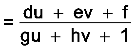
- the objective of the calibration is to define the functions R and T giving respectively the abscissa x and the ordinate z of any point M of the laser plane P as a function of the column u and the line v of its image N:
- the eight unknowns constituted by the coefficients a, b, c, d, e, f, g, h are determined by applying these equations to at least four rods M k for which x k , z k , u k and v k are known:
Landscapes
- Health & Medical Sciences (AREA)
- Life Sciences & Earth Sciences (AREA)
- Engineering & Computer Science (AREA)
- Physics & Mathematics (AREA)
- Surgery (AREA)
- Public Health (AREA)
- Pathology (AREA)
- General Physics & Mathematics (AREA)
- Biomedical Technology (AREA)
- Heart & Thoracic Surgery (AREA)
- Medical Informatics (AREA)
- Molecular Biology (AREA)
- Veterinary Medicine (AREA)
- Animal Behavior & Ethology (AREA)
- General Health & Medical Sciences (AREA)
- Biophysics (AREA)
- Dentistry (AREA)
- Oral & Maxillofacial Surgery (AREA)
- Automation & Control Theory (AREA)
- Nuclear Medicine, Radiotherapy & Molecular Imaging (AREA)
- Radiology & Medical Imaging (AREA)
- Computer Vision & Pattern Recognition (AREA)
- Length Measuring Devices By Optical Means (AREA)
- Placing Or Removing Of Piles Or Sheet Piles, Or Accessories Thereof (AREA)
- Length Measuring Devices With Unspecified Measuring Means (AREA)
Claims (24)
- Verfahren zum Digitalisieren der Oberfläche eines dreidimensionalen Gegenstandes (oder Inhaltes), mit dem digitale Daten erzeugbar sind, die die Koordinaten der Punkte dieser Oberfläche in einem dreidimensionalen Bezugssystem repräsentieren, in dem:- die Oberfläche des Gegenstandes durch zumindest zwei lamellenförmige Strahlenbündel beleuchtet wird, um Lichtspuren auf der Oberfläche gemäß den Oberflächen, die mit zu der Drehachse (Z) parallelen Ebenen (P₁, P₂) zusammenfallend oder benachbart oder durch diese Achse hindurchgehend ausgerichtet sind, zu erzeugen, wobei die Strahlenbündel von Quellen (L₁, L₂) ausgegeben werden, die in Längsrichtung dieser Drehachse geometrisch versetzt liegen, so daß die Achsen der Strahlenbündel mit der Drehachse unterschiedliche Winkel (l₁, l₂) bilden,- der Gegenstand mittels einer Videovorrichtung mit einer vorbestimmten Parallaxe (P₁, P₂) in bezug auf die Strahlenbündel gefilmt wird, um ein Videosignal auszugeben, das die Koordinaten der Punkte der Lichtspuren repräsentiert, wobei zumindest zwei unterschiedliche Blickpunkte (C₁, C₂) entlang der Drehachse (Z) geometrisch versetzt liegen, so daß die winkel (c₁, c₂) der entsprechenden Aufnahmen (in bezug auf die Drehachse betrachtet) unterschiedlich sind, um die Videosignale entsprechend den Blickpunkten zu liefern,- die gesamte Video-/Strahlenbündelvorrichtung einer relativen Drehbewegung um eine Achse (Z) in bezug zu dem Gegenstand unterzogen wird, um so die gesamte Oberfläche des Gegenstandes zu beleuchten und zu filmen,- eine die Winkelposition (Θ) wiedergebende Information erzeugt wird, welche repräsentativ ist für jedes Bild der entsprechenden Winkelposition der Video/Strahlenbündelvorrichtung in bezug zu dem Gegenstand,- die Videosignale, die für jedes Bild repräsentativ sind, und die Informationen über die Winkelpositionen der Bilder (Θ) in digitale Daten umgewandelt werden,- die Videosignale digitalisiert werden, indem in jeder Zeile die Position der aktivierten Pixel kodiert wird und diese digitalisierten Positionen (u₁, v₁; u₂, v₂...) gespeichert werden,- für jedes Bild eine Unterteilung der digitalisierten Positionen durchgeführt wird, um die den durch jedes Strahlenbündel erzeugten Spuren entsprechenden digitalisierten Positionen zu unterscheiden,- aus den Informationen zur Winkelposition, die mit jedem Bild (Θ) verbunden sind, und aus den Informationen (p₁, p₂, c₁, c₂; a-h; αij, βij, γij), die die Geometrie der gesamten Video-/Strahlenbündelvorrichtung repräsentieren, spezifische Informationen erzeugt werden, die jeder Spur anhaften,- und, für jedes Bild aus den digitalisierten Positionen, entsprechend jeder Spur (u₁, v₁, v₁ oder u₂, v₂ ...), die an der betrachteten Spur anhaftenden Informationen zugeordnet werden,
dadurch gekennzeichnet,
daß die Informationen, die die Geometrie der gesamten Video-/Strahlenbündelvorrichtung repräsentieren, durch ein Kalibrierverfahren bestimmt werden, bestehend aus:- zuerst die Digitalisierung eines Kalibrier-Testobjektes (33) anstelle eines Gegenstandes durchzuführen, wobei das Testobjekt vorher gespeicherte geometrische Reliefs und bekannte Dimensionen aufweist,- und, die Funktionen x = R (u, v), z = T (u, v) zu berechnen, die die metrischen Koordinaten der Punkte jeder Laserebene als Funktion der Spalten und Zeilen des entsprechenden Bildes liefern, wobei aus den Ergebnissen der vorerwähnten Digitalisierung die spezifischen Informationen, die an jeder Spur anhaften, durch Anwendung dieser Funktionen erhalten werden. - Verfahren nach Anspruch 1, in dem in Kombination:- der Gegenstand von zwei Blickpunkten (C₁, C₂) gefilmt wird, die in einer die Drehachse (Z) enthaltende Mittelebene (M) oder in Nachbarschaft von dieser in unterschiedlichen Höhen liegen, um einen abtauchenden Aufnahmewinkel (c₁) und den anderen von unten auftauchend (c₂) zu liefern,- die Oberfläche des Gegenstandes durch zwei scharfe Strahlenbündel beleuchtet wird, die von zwei Quellen (L₁, L₂) ausgegeben werden, die beiderseits der Mittelebene (M) an unterschiedlichen Höhen liegen, um einereseits abtauchend (l₁), andererseits auftauchend (l₂) zu beleuchten.
- Verfahren nach Anspruch 2,
dadurch gekennzeichnet,
daß der Gegenstand von zwei Blickpunkten (C₁, C₂) aus gefilmt wird, so daß die Kamerabereiche genau getrennt sind und jeweils einem Halbraum (E₁, E₂) entsprechen, der an der einen und der anderen Seite der Mittelebene (M) liegt, um so von jedem Blickpunkt aus die Spur von einem einzigen Strahlenbündel zu filmen. - Verfahren nach Anspruch 1, in dem in Kombination:- die Oberfläche des Gegenstandes aus zwei in der Höhe versetzt liegenden Quellen (L′₁, L′₂) durch zwei Strahlenbündel beleuchtet wird, die in einer die Drehachse (Z′) enthaltenen Mittelebene (M′) liegen, oder die einer solchen Ebene benachbart liegen, um einerseits abtauchend (l′₁), andererseits auftauchend (l′₂) zu beleuchten,- der Gegenstand von zwei Blickpunkten (C′₁, C′₂) gefilmt wird, die beiderseits der vorbeschriebenen Mittelebene (M′) an unterschiedlichen Höhen liegen, um einen abtauchenden (c₁) und einen auftauchenden (c₂) Aufnahmewinkel zu liefern.
- Verfahren nach Anspruch 4,
dadurch gekennzeichnet,
daß der Gegenstand von zwei Blickpunkten (C′₁, C′₂) gefilmt wird, so daß sich die Kamerabereiche auf dem Niveau des Gegenstandes überdecken und die Spur der zwei Strahlenbündel enthalten. - Verfahren nach einem der Ansprüche 1, 2, 3, 4 oder 5, in dem der Gegenstand zumindest von einer einzigen Kamera (11) gefilmt wird, durch Reflexion über zwei Spiegelgruppen (12 c₁, 13 c₁; 14 c₂, 15 c₂,), die geometrisch angeordnet sind, um die zwei vorbeschriebenen Blickpunkte (C₁, C₂) zu erzeugen und die Lichtwege auf die benachbarte Länge zu konditionieren, um ein einziges Videosignal zu liefern, das zwei Halbbilder repräsentiert entsprechend jedem Blickpunkt.
- Verfahren nach Anspruch 6, gefaßt in Abhängigkeit von Anspruch 3,
dadurch gekennzeichnet,
daß das Videosignal digitalisiert wird, indem in jeder Zeile die Position der aktivierten Pixel kodiert wird, und daß die Einteilung der digitalisierten Positionen als Funktion ihres Wertes in bezug auf einen Medianwert, der der Position der Drehachse (Z) in dem Bild entspricht, durchgeführt wird. - Verfahren nach einem der Ansprüche nach 1, 2, 3, 4 oder 5,
dadurch gekennzeichnet,
daß der Gegenstand mittels zwei Kameras gefilmt wird, wobei jede so angeordnet ist, daß sie gemäß einem der vorbeschriebenen Blickpunkte (C′₁, C′₂) beobachten kann, um zwei Videosignale zu liefern, die zwei den zwei Blickpunkten entsprechende Bilder repräsentieren. - Verfahren nach Anspruch 8, gefaßt in Abhängigkeit von Anspruch 4,
dadurch gekennzeichnet,
daß die zwei Videosignale multiplext werden hinsichtlich ihrer Digitalisierung, und daß für jedes Bild die Einteilung der digitalisierten Positionen in Abhängigkeit von der Kamera, von der das betrachtete Bild ausgegeben wird, durchgeführt wird. - Verfahren nach einem der Ansprüche 1, 2, 3, 4, 5, 6, 7, 8 oder 9, in dem die Oberfläche des Gegenstandes durch definierte Quellen mit zwei scharfen Laservorrichtungen (16l₁, 17l₂) beleuchtet wird.
- Verfahren nach einem der Ansprüche 1-10, in dem die Informationen, die die Geometrie der gesamten Video/Strahlenbündelvorrichtung repräsentieren, aus den zuvor gemessenen Abständen und winkeln (p₁, p₂, c₁, c₂) gebildet und in einem Speicher (26) gespeichert werden, wobei die an jeder Spur anhaftenden spezifischen Informationen die Punktkoordinaten dieser Spuren sind, die durch trigonometrische Berechnungen berechnet werden.
- Verfahren nach Anspruch 1,
dadurch gekennzeichnet,
daß das Kalibrier-Testobjekt aus einer Platte (33a) gebildet wird, die auf einer Fläche ein Netz aus Peilstäben (33b) trägt, wobei die Digitalisierung für jede Laserebene bewirkt wird, indem die Platte (33a) parallel zur Fläche des Strahlenbündels angeordnet wird, so daß die Peilstäbe das Strahlenbündel abfangen. - Verfahren nach einem der Ansprüche 1 oder 12,
dadurch gekennzeichnet,
daß die Linearfunktionen aus der Formel
- Verfahren nach einem der Ansprüche 1 oder 12,
dadurch gekennzeichnet,
daß die nicht-linearen Funktionen nach der Formel


- Verfahren nach einem der Ansprüche 1-14,
dadurch gekennzeichnet,
daß der Gegenstand festliegt und von der Drehachse (Z) durchquert wird, und die gesamte Video/Strahlenbündelvorrichtung veranlaßt wird, sich um die Drehachse (Z) zu drehen. - Vorrichtung zum dreidimensionalen Aufnehmen der Oberfläche eines Gegenstandes (oder Inhaltes), um ein Videosignal zu liefern, das die Koordinaten der Punkte dieser Oberfläche repräsentiert, mit:- einer Anlage zur Beleuchtung des Gegenstandes (16l₁, 17l₂), die so ausgebildet ist, daß zwei geometrisch in Längsrichtung der Drehachse versetzte Quellen (L₁, L₂) definiert sind, um auf die Oberfläche des Gegenstandes zwei scharfe Strahlen, die sich in parallelen Ebenen zur Drehachse (Z) ausbreiten oder durch diese hindurchgehen, auszusenden, wobei die Achsen der Strahlenbündel mit der Drehachse (Z) zwei unterschiedliche winkel (l₁, l₂) bilden,- einer mit der Beleuchtungsanlage mechanisch einstückigen Videovorrichtung (11, 12c₁, 13c₁, 14c₁, 15c₂), geeignet, den Gegenstand mit einer in bezug auf die Strahlenbündel der Beleuchtungsanlage vorbestimmten Parallaxe zu filmen, die so ausgebildet ist, daß die Bilder des Gegenstandes von zwei unterschiedlichen Blickpunkten (C₁, C₂) aufgenommen werden, die entlang der Drehachse (Z) so geometrisch versetzt liegen, daß die zwei entsprechenden Blickwinkel (c₁, c₂) in bezug zur Drehachse betrachtet unterschiedlich sind, um so geeignet zu sein, ein oder mehrere Videosignale entsprechend der Blickpunkte zu liefern,- Mitteln (3, 10) zum Positionieren des Gegenstandes auf der Strahlenbahn der Beleuchtungsanlage und im Feld der Videovorrichtung,- Mitteln (4-7) zum Verstellen der gesamten Beleuchtungsanlage/Videovorrichtung durch eine Relativdrehung um eine Drehachse (Z) in bezug auf den Gegenstand,dadurch gekennzeichnet,
daß die Drehstütze (9) mit einer Zentriereinrichtung (10) versehen ist, die auf der Verlängerung der Abtriebswelle (7) sitzt und so ausgebildet ist, daß eine Positionierung des Gegenstandes sichergestellt ist, und daß die Zentriereinrichtung (10) so ausgebildet ist, daß zumindest zwei Arten von abnehmbaren Ansatzstücken aufgenommen sind, wobei das eine (10a, 34) zum Aufstützen auf den zur digitalisierenden Gegenstand ausgebildet ist, und das andere (36) zum Abstützen und Zentrieren eines der Vorrichtung zugeordneten Kalibrier-Testobjektes (33) ausgebildet ist, und daß sie Kalibriereinrichtungen umfaßt, die geeignet sind, das Oberflächenbild des Testobjektes zu digitalisieren und aus den Ergebnissen der Digitalisierung die Funktionen x = R (u, v) und z = T (u, v) zu berechnen, die die metrischen Koordinaten der Punkte jeder Laserfläche in Abhängigkeit von den Spalten und Zeilen des entsprechenden Bildes wiedergeben, wobei die an jeder Spur anhaftenden spezifischen Informationen daraufhin durch Anwendung dieser Funktionen erhalten werden. - Vorrichtung nach Anspruch 16, in der in Kombination:- die Videovorrichtung eine Videokamera (11), die besonders empfindlich auf eine vorbestimmte Wellenlänge ist, und zwei Spiegelgruppen (12c₁, 13c₁; 14c₂, 15c₂ ...), die geometrisch angeordnet sind, um zwei Blickpunkte (C₁, C₂) zu erzeugen, die in einer die Drehachse (Z) enthaltenen Mittelebene (M) liegen, wobei eine der Gruppen einen abtauchenden, die andere einen auftauchenden Blickwinkel liefert, umfaßt,- die Beleuchtungsanlage zwei lamellenförmige Laservorrichtungen (16l₁, 17l₁) mit einer Wellenlänge, die mit der der Kamera übereinstimmt, umfaßt, welche so angeordnet sind, daß die Quellen (L₁, L₂), die seitlich auf der einen und anderen Seite der vorbeschriebenen Mittelebene (M) an unterschiedlichen Höhen angeordnet sind, um einerseits abtauchend, andererseits auftauchend zu leuchten.
- Vorrichtung nach Anspruch 17,
dadurch gekennzeichnet,
daß die Spiegelgruppen (12c₁, 13c₁; 14c₂, 15c₂) so ausgerichtet sind, daß sie Kamerabereiche, die genau getrennt sind, jeweils entsprechend den auf der einen und der anderen Seite der Mittelebene (M) gelegenen Halbräumen (E₁, E₂), abdecken, wobei die Spiegelgruppe (12c₁, 13c₁) einen abtauchenden Blickwinkel (c₁), der den auf der Seite der abtauchend leuchtenden Laserquelle (L₁) liegenden Halbraum (E₁) abdeckt, liefert, und umgekehrt für den auftauchenden. - Vorrichtung nach einem der Ansprüche 17 oder 18,
dadurch gekennzeichnet,
daß diese einen Träger (1), einen Elektromotor (4), der mit einem Untersetzungsgetriebe (5) verbunden ist, die von dem Träger getragen werden, eine Übertragungseinrichtung (6), die mit dem Untersetzungsgetriebe verbunden ist und eine mit der Drehachse (Z) co-lineare Abtriebswelle (7) aufweist, und eine Drehstütze (9) umfaßt, die auf der Abtriebswelle sitzt, wobei die Videokamera (11), die Spiegelgruppen (12c₁, 13c₁; 14c₂, 15c₂) und die Laservorrichtungen (16l₁, 17l₂) abhängig von der Drehstütze (9) sind. - Vorrichtung nach einem der Ansprüche 16-19, in der ein Meßfühler für die Winkelposition (8) mit einer Dreh-Verstelleinrichtung (4-7) verbunden ist, wobei der Meßfühler so ausgebildet ist, daß er ein Signal liefert, daß die relative Winkelposition der gesamten Beleuchtungsanlage/Videovorrichtung in bezug zu dem Gegenstand repräsentiert.
- Vorrichtung gemäß Anspruch 20, gefaßt in Abhängigkeit von Anspruch 19,
dadurch gekennzeichnet,
daß der Meßfühler der Winkelposition (8) einen elektrischen Taktgeber mit einer der Drehgeschwindigkeit proportionalen Frequenz umfaßt, der an die welle des Elektromotors gekoppelt ist. - Vorrichtung nach Anspruch 16,
dadurch gekennzeichnet,
daß das Kalibrier-Testobjekt eine Platte (33a) umfaßt, die mit einem Netz von Peilstäben (33b) versehen ist. - Vorrichtung nach einem der Ansprüche 19-22,
dadurch gekennzeichnet,
daß die Drehstütze (9) einerseits eine stirnseitige Erstreckung(9a), die vor der Zentriereinrichtung (10) liegt und die Spiegelgruppen (12c₁, 13c₁; 14c₂, 15c₂) und die Laservorrichtungen (16l₁, 17l₂) trägt, und andererseits eine obenliegende Erstreckung (9b) aufweist, die die Kamera (11) trägt, wobei die Zentriereinrichtung (10) durchbrochen ist, um den optischen weg zwischen Kamera und Spiegelgruppen freizumachen. - Vorrichtung nach einem der Ansprüche 16-23, so ausgebildet, daß die Aufnahme eines Kopfes oder eines menschlichen Oberkörpers durchführbar ist.
Priority Applications (1)
| Application Number | Priority Date | Filing Date | Title |
|---|---|---|---|
| AT89400325T ATE84366T1 (de) | 1988-02-09 | 1989-02-06 | Verfahren zum digitalisieren der oberflaeche eines dreidimensionalen gegenstandes und aufnahmevorrichtung zur anwendung dieses verfahrens. |
Applications Claiming Priority (2)
| Application Number | Priority Date | Filing Date | Title |
|---|---|---|---|
| FR8801897 | 1988-02-09 | ||
| FR8801897A FR2627047B1 (fr) | 1988-02-09 | 1988-02-09 | Procede de numerisation de la surface d'un objet tridimensionnel et appareil de releve en vue de sa mise en oeuvre |
Publications (2)
| Publication Number | Publication Date |
|---|---|
| EP0328443A1 EP0328443A1 (de) | 1989-08-16 |
| EP0328443B1 true EP0328443B1 (de) | 1993-01-07 |
Family
ID=9363348
Family Applications (1)
| Application Number | Title | Priority Date | Filing Date |
|---|---|---|---|
| EP89400325A Expired - Lifetime EP0328443B1 (de) | 1988-02-09 | 1989-02-06 | Verfahren zum Digitalisieren der Oberfläche eines dreidimensionalen Gegenstandes und Aufnahmevorrichtung zur Anwendung dieses Verfahrens |
Country Status (8)
| Country | Link |
|---|---|
| EP (1) | EP0328443B1 (de) |
| AT (1) | ATE84366T1 (de) |
| CA (1) | CA1314619C (de) |
| DE (1) | DE68904205T2 (de) |
| ES (1) | ES2036805T3 (de) |
| FR (1) | FR2627047B1 (de) |
| GR (1) | GR3006751T3 (de) |
| WO (1) | WO1989007750A1 (de) |
Cited By (1)
| Publication number | Priority date | Publication date | Assignee | Title |
|---|---|---|---|---|
| WO2018160902A1 (en) * | 2017-03-02 | 2018-09-07 | DSCG Solutions, Inc. | Dwell-angle-independent tracking and monitoring objects using lidar |
Families Citing this family (9)
| Publication number | Priority date | Publication date | Assignee | Title |
|---|---|---|---|---|
| DE4019866A1 (de) * | 1990-06-22 | 1992-01-02 | Wernicke & Co Gmbh | Verfahren und vorrichtung zum abtasten und speichern der daten einer oeffnung eines brillengestells oder einer schablone |
| FR2685764B1 (fr) * | 1991-12-30 | 1995-03-17 | Kreon Ind | Capteur optique compact et a haute resolution pour l'analyse de formes tridimensionnelles. |
| GB9209594D0 (en) * | 1992-05-02 | 1992-06-17 | British United Shoe Machinery | Apparatus for digitising a surface portion of a three-dimensional article |
| AUPN169795A0 (en) * | 1995-03-13 | 1995-04-06 | Herbert, David Russell | Method and system for transforming a computer graphic file |
| JP3016476U (ja) * | 1995-04-01 | 1995-10-03 | 株式会社ペティオ | 立体加工装置 |
| GB9515311D0 (en) | 1995-07-26 | 1995-09-20 | 3D Scanners Ltd | Stripe scanners and methods of scanning |
| DE19705883A1 (de) * | 1997-02-15 | 1998-08-20 | Guenter Wensing | Verfahren und Vorrichtung zum Kopieren von dreidimensionalen Gegenständen |
| DE10232690A1 (de) | 2002-07-18 | 2004-02-12 | Siemens Ag | Verfahren und Vorrichtung zur dreidimensionalen Erfassung von Objekten sowie Verwendung der Vorrichtung und des Verfahrens |
| JP4615514B2 (ja) * | 2004-04-15 | 2011-01-19 | 株式会社モリテックス | 顔面撮像装置 |
Family Cites Families (8)
| Publication number | Priority date | Publication date | Assignee | Title |
|---|---|---|---|---|
| DE1157809B (de) * | 1962-05-19 | 1963-11-21 | Contina Ag | Betrachtungsgeraet |
| US4147433A (en) * | 1976-12-17 | 1979-04-03 | United Technologies Corporation | Contour inspection |
| LU78624A1 (de) * | 1977-12-02 | 1978-04-20 | ||
| FR2470415A1 (fr) * | 1979-11-23 | 1981-05-29 | Option Sa | Dispositif de localisation ou de reconnaissance de la forme d'un objet, combinant un organe d'eclairage par faisceau laser et une camera de television |
| FR2519138B1 (fr) * | 1981-12-29 | 1985-08-30 | Maitre Henri | Procede et appareil automatique pour la numerisation d'une surface tridimensionnelle |
| US4752964A (en) * | 1984-04-17 | 1988-06-21 | Kawasaki Jukogyo Kabushiki Kaisha | Method and apparatus for producing three-dimensional shape |
| EP0233920B1 (de) * | 1985-08-12 | 1991-01-23 | Cyberware Laboratory Inc | Schneller digitalisierer einer dreidimensionalen oberfläche |
| GB8524473D0 (en) * | 1985-10-04 | 1985-11-06 | Loughborough Consult Ltd | Making measurements on body |
-
1988
- 1988-02-09 FR FR8801897A patent/FR2627047B1/fr not_active Expired - Fee Related
-
1989
- 1989-02-06 DE DE8989400325T patent/DE68904205T2/de not_active Expired - Fee Related
- 1989-02-06 AT AT89400325T patent/ATE84366T1/de not_active IP Right Cessation
- 1989-02-06 ES ES198989400325T patent/ES2036805T3/es not_active Expired - Lifetime
- 1989-02-06 WO PCT/FR1989/000045 patent/WO1989007750A1/fr not_active Ceased
- 1989-02-06 EP EP89400325A patent/EP0328443B1/de not_active Expired - Lifetime
- 1989-02-06 CA CA000590219A patent/CA1314619C/fr not_active Expired - Fee Related
-
1993
- 1993-01-08 GR GR920403020T patent/GR3006751T3/el unknown
Cited By (2)
| Publication number | Priority date | Publication date | Assignee | Title |
|---|---|---|---|---|
| WO2018160902A1 (en) * | 2017-03-02 | 2018-09-07 | DSCG Solutions, Inc. | Dwell-angle-independent tracking and monitoring objects using lidar |
| US11262454B2 (en) | 2017-03-02 | 2022-03-01 | DSCG Solutions, Inc. | Dwell-angle-independent tracking and monitoring objects using LIDAR |
Also Published As
| Publication number | Publication date |
|---|---|
| DE68904205D1 (de) | 1993-02-18 |
| FR2627047A1 (fr) | 1989-08-11 |
| CA1314619C (fr) | 1993-03-16 |
| EP0328443A1 (de) | 1989-08-16 |
| ATE84366T1 (de) | 1993-01-15 |
| DE68904205T2 (de) | 1993-05-06 |
| GR3006751T3 (de) | 1993-06-30 |
| WO1989007750A1 (fr) | 1989-08-24 |
| FR2627047B1 (fr) | 1990-07-27 |
| ES2036805T3 (es) | 1993-06-01 |
Similar Documents
| Publication | Publication Date | Title |
|---|---|---|
| EP0278882B1 (de) | Verfahren und Vorrichtung zum Erstellen eines Abdrucks für medizinische Zwecke | |
| EP0452422B1 (de) | Kalibrierungsverfahren eines dreidimensionalen formerfassungssystems und system zur durchführung des genannten verfahrens | |
| EP0279730B1 (de) | Vorrichtung und Verfahren für dreidimensionale Vermessung | |
| EP2606817B1 (de) | System zur Wiederherstellung der optischen Eigenschaften eines Diffusionsmediums, das eine pulsierende Strahlungsquelle und mindestens zwei Detektoren unterschiedlichen Typs umfasst, und entsprechendes Wiederherstellungsverfahren | |
| EP0328443B1 (de) | Verfahren zum Digitalisieren der Oberfläche eines dreidimensionalen Gegenstandes und Aufnahmevorrichtung zur Anwendung dieses Verfahrens | |
| FR2836215A1 (fr) | Systeme et procede de modelisation et de restitution tridimensionnelle d'un objet | |
| FR2756626A1 (fr) | Systeme de mesure de jeux et d'affleurements entre des pieces en vis-a-vis | |
| EP0647829B1 (de) | Verfahren und Vorrichtung zur geometrischen Kontrolle eines Fahrzeugs | |
| EP0600800A1 (de) | Verfahren und Vorrichtung zur Herstellung eines Bildes, in drei Dimensionen, eines kleines Objekts durch optische Abtastung und ein Kalibrierverfahren für eine solche Herstellung | |
| WO2008081149A2 (fr) | Procede optico-informatique de mesure 3d d'un objet en relief par projection de franges et utilisation d'une methode a decalage de phase, systeme correspondant | |
| FR2624600A1 (fr) | Procede et dispositif de controle de contours geometriques sans contact | |
| EP4143503B1 (de) | System zur erzeugung eines signals, das das profil einer relativ zum system bewegten oberfläche repräsentiert | |
| EP0320391B1 (de) | Video-Laser-Detektionsvorrichtung zur Erfassung der geometrischen Charakteristika eines Gegenstandes | |
| EP3724725B1 (de) | Verfahren zur kalibrierung einer analysevorrichtung und zugehörige vorrichtung | |
| FR2529342A1 (fr) | Procede et dispositif de controle sonique de pieces | |
| FR2622968A1 (fr) | Procede et dispositif pour effectuer le controle dimensionnel d'une piece par voie optoelectronique | |
| EP0069071A2 (de) | Identifikationsverfahren eines Objekts und Messung seiner Rotation und seiner Orientation und Vorrichtung zur Ausführung dieses Verfahrens | |
| FR3074353B1 (fr) | Systeme d'imagerie tridimensionnelle d'ondes de pression acoustiques | |
| Gaburro et al. | Conoscopic laser microprofilometry for 3D digital reconstruction of surfaces with sub-millimeter resolution | |
| FR2558257A1 (fr) | Endoscope electronique | |
| CA3075230A1 (fr) | Dispositif de mesure optique par lumiere polarisee de doses d'irradiation absorbee par un gel dosimetrique | |
| FR2780169A1 (fr) | Procede et appareil pour la mesure du repere d'un mouvement de montre mecanique | |
| FR2536167A1 (fr) | Camera optoelectronique, procede de relevement, a l'aide de cette camera, du profil d'une section transversale d'une cavite, et installation pour la mise en oeuvre du procede | |
| FR2928729A1 (fr) | Dispositif de detection ou de reception d'un rayonnement laser | |
| FR2692060A1 (fr) | Dispositif de traitement d'images du type extracteur de contour et senseur de terre comprenant un tel extracteur. |
Legal Events
| Date | Code | Title | Description |
|---|---|---|---|
| PUAI | Public reference made under article 153(3) epc to a published international application that has entered the european phase |
Free format text: ORIGINAL CODE: 0009012 |
|
| AK | Designated contracting states |
Kind code of ref document: A1 Designated state(s): AT BE DE ES FR GB GR IT NL SE |
|
| 17P | Request for examination filed |
Effective date: 19900126 |
|
| 17Q | First examination report despatched |
Effective date: 19910503 |
|
| RAP1 | Party data changed (applicant data changed or rights of an application transferred) |
Owner name: SA KREON INDUSTRIE |
|
| GRAA | (expected) grant |
Free format text: ORIGINAL CODE: 0009210 |
|
| AK | Designated contracting states |
Kind code of ref document: B1 Designated state(s): AT BE DE ES FR GB GR IT NL SE |
|
| REF | Corresponds to: |
Ref document number: 84366 Country of ref document: AT Date of ref document: 19930115 Kind code of ref document: T |
|
| ITF | It: translation for a ep patent filed | ||
| REF | Corresponds to: |
Ref document number: 68904205 Country of ref document: DE Date of ref document: 19930218 |
|
| GBT | Gb: translation of ep patent filed (gb section 77(6)(a)/1977) |
Effective date: 19930408 |
|
| REG | Reference to a national code |
Ref country code: GR Ref legal event code: FG4A Free format text: 3006751 |
|
| REG | Reference to a national code |
Ref country code: ES Ref legal event code: FG2A Ref document number: 2036805 Country of ref document: ES Kind code of ref document: T3 |
|
| PLBE | No opposition filed within time limit |
Free format text: ORIGINAL CODE: 0009261 |
|
| STAA | Information on the status of an ep patent application or granted ep patent |
Free format text: STATUS: NO OPPOSITION FILED WITHIN TIME LIMIT |
|
| 26N | No opposition filed | ||
| EAL | Se: european patent in force in sweden |
Ref document number: 89400325.0 |
|
| PGFP | Annual fee paid to national office [announced via postgrant information from national office to epo] |
Ref country code: GB Payment date: 20010207 Year of fee payment: 13 |
|
| PGFP | Annual fee paid to national office [announced via postgrant information from national office to epo] |
Ref country code: FR Payment date: 20010220 Year of fee payment: 13 |
|
| PGFP | Annual fee paid to national office [announced via postgrant information from national office to epo] |
Ref country code: SE Payment date: 20010223 Year of fee payment: 13 |
|
| PGFP | Annual fee paid to national office [announced via postgrant information from national office to epo] |
Ref country code: NL Payment date: 20010227 Year of fee payment: 13 |
|
| PGFP | Annual fee paid to national office [announced via postgrant information from national office to epo] |
Ref country code: GR Payment date: 20010228 Year of fee payment: 13 Ref country code: ES Payment date: 20010228 Year of fee payment: 13 Ref country code: AT Payment date: 20010228 Year of fee payment: 13 |
|
| PGFP | Annual fee paid to national office [announced via postgrant information from national office to epo] |
Ref country code: BE Payment date: 20010309 Year of fee payment: 13 |
|
| PGFP | Annual fee paid to national office [announced via postgrant information from national office to epo] |
Ref country code: DE Payment date: 20010424 Year of fee payment: 13 |
|
| REG | Reference to a national code |
Ref country code: GB Ref legal event code: IF02 |
|
| PG25 | Lapsed in a contracting state [announced via postgrant information from national office to epo] |
Ref country code: GB Free format text: LAPSE BECAUSE OF NON-PAYMENT OF DUE FEES Effective date: 20020206 Ref country code: AT Free format text: LAPSE BECAUSE OF NON-PAYMENT OF DUE FEES Effective date: 20020206 |
|
| PG25 | Lapsed in a contracting state [announced via postgrant information from national office to epo] |
Ref country code: SE Free format text: LAPSE BECAUSE OF NON-PAYMENT OF DUE FEES Effective date: 20020207 Ref country code: ES Free format text: LAPSE BECAUSE OF NON-PAYMENT OF DUE FEES Effective date: 20020207 |
|
| PG25 | Lapsed in a contracting state [announced via postgrant information from national office to epo] |
Ref country code: BE Free format text: LAPSE BECAUSE OF NON-PAYMENT OF DUE FEES Effective date: 20020228 |
|
| BERE | Be: lapsed |
Owner name: SA KREON INDUSTRIE Effective date: 20020228 |
|
| PG25 | Lapsed in a contracting state [announced via postgrant information from national office to epo] |
Ref country code: NL Free format text: LAPSE BECAUSE OF NON-PAYMENT OF DUE FEES Effective date: 20020901 |
|
| PG25 | Lapsed in a contracting state [announced via postgrant information from national office to epo] |
Ref country code: DE Free format text: LAPSE BECAUSE OF NON-PAYMENT OF DUE FEES Effective date: 20020903 |
|
| PG25 | Lapsed in a contracting state [announced via postgrant information from national office to epo] |
Ref country code: GR Free format text: LAPSE BECAUSE OF NON-PAYMENT OF DUE FEES Effective date: 20020909 |
|
| EUG | Se: european patent has lapsed |
Ref document number: 89400325.0 |
|
| GBPC | Gb: european patent ceased through non-payment of renewal fee |
Effective date: 20020206 |
|
| PG25 | Lapsed in a contracting state [announced via postgrant information from national office to epo] |
Ref country code: FR Free format text: LAPSE BECAUSE OF NON-PAYMENT OF DUE FEES Effective date: 20021031 |
|
| NLV4 | Nl: lapsed or anulled due to non-payment of the annual fee |
Effective date: 20020901 |
|
| REG | Reference to a national code |
Ref country code: FR Ref legal event code: ST |
|
| REG | Reference to a national code |
Ref country code: ES Ref legal event code: FD2A Effective date: 20030922 |
|
| PG25 | Lapsed in a contracting state [announced via postgrant information from national office to epo] |
Ref country code: IT Free format text: LAPSE BECAUSE OF NON-PAYMENT OF DUE FEES Effective date: 20050206 |