EP0328146A2 - Colonne pour chromatographie liquide à haute pression - Google Patents
Colonne pour chromatographie liquide à haute pression Download PDFInfo
- Publication number
- EP0328146A2 EP0328146A2 EP89102368A EP89102368A EP0328146A2 EP 0328146 A2 EP0328146 A2 EP 0328146A2 EP 89102368 A EP89102368 A EP 89102368A EP 89102368 A EP89102368 A EP 89102368A EP 0328146 A2 EP0328146 A2 EP 0328146A2
- Authority
- EP
- European Patent Office
- Prior art keywords
- column
- flange
- housing
- collar
- coupler
- Prior art date
- Legal status (The legal status is an assumption and is not a legal conclusion. Google has not performed a legal analysis and makes no representation as to the accuracy of the status listed.)
- Granted
Links
Images
Classifications
-
- G—PHYSICS
- G01—MEASURING; TESTING
- G01N—INVESTIGATING OR ANALYSING MATERIALS BY DETERMINING THEIR CHEMICAL OR PHYSICAL PROPERTIES
- G01N30/00—Investigating or analysing materials by separation into components using adsorption, absorption or similar phenomena or using ion-exchange, e.g. chromatography or field flow fractionation
- G01N30/02—Column chromatography
- G01N30/04—Preparation or injection of sample to be analysed
- G01N30/16—Injection
- G01N30/22—Injection in high pressure liquid systems
-
- G—PHYSICS
- G01—MEASURING; TESTING
- G01N—INVESTIGATING OR ANALYSING MATERIALS BY DETERMINING THEIR CHEMICAL OR PHYSICAL PROPERTIES
- G01N30/00—Investigating or analysing materials by separation into components using adsorption, absorption or similar phenomena or using ion-exchange, e.g. chromatography or field flow fractionation
- G01N30/02—Column chromatography
- G01N30/60—Construction of the column
- G01N30/6091—Cartridges
-
- G—PHYSICS
- G01—MEASURING; TESTING
- G01N—INVESTIGATING OR ANALYSING MATERIALS BY DETERMINING THEIR CHEMICAL OR PHYSICAL PROPERTIES
- G01N30/00—Investigating or analysing materials by separation into components using adsorption, absorption or similar phenomena or using ion-exchange, e.g. chromatography or field flow fractionation
- G01N30/02—Column chromatography
- G01N30/04—Preparation or injection of sample to be analysed
- G01N30/06—Preparation
- G01N30/08—Preparation using an enricher
- G01N2030/085—Preparation using an enricher using absorbing precolumn
-
- G—PHYSICS
- G01—MEASURING; TESTING
- G01N—INVESTIGATING OR ANALYSING MATERIALS BY DETERMINING THEIR CHEMICAL OR PHYSICAL PROPERTIES
- G01N30/00—Investigating or analysing materials by separation into components using adsorption, absorption or similar phenomena or using ion-exchange, e.g. chromatography or field flow fractionation
- G01N30/02—Column chromatography
- G01N30/60—Construction of the column
- G01N30/6004—Construction of the column end pieces
- G01N30/6026—Fluid seals
-
- G—PHYSICS
- G01—MEASURING; TESTING
- G01N—INVESTIGATING OR ANALYSING MATERIALS BY DETERMINING THEIR CHEMICAL OR PHYSICAL PROPERTIES
- G01N30/00—Investigating or analysing materials by separation into components using adsorption, absorption or similar phenomena or using ion-exchange, e.g. chromatography or field flow fractionation
- G01N30/02—Column chromatography
- G01N30/60—Construction of the column
- G01N30/6004—Construction of the column end pieces
- G01N30/603—Construction of the column end pieces retaining the stationary phase, e.g. Frits
Definitions
- the present invention finds application in the field of liquid chromatography and relates to a column assembly coupled between a liquid chromatograph injector and a detector.
- a liquid (called the “mobile phase”) is pumped under high pressure through a separation or partition column, which comprises a tubular member packed with a suitable particulate solid material (the “stationary phase”).
- the stationary phase As the liquid phase, including a small sample to be separated or assayed, passes through the column the sample components in the liquid phase separate from each other. As the liquid phase elutes from the column, the sample is separated into bands whose concentration is then measured by a suitable detector.
- a liquid chromatograph column in some user situations, may need to be changed frequently. Such column changing may be necessary, for example, in order to permit testing of a sample with a column having a different stationary phase.
- Most column changes are made by removing the column from the tubing which couples it to the detector and the sample injector. This usually necessitates the use of wrenches, a fact which in some industrial settings may require the chromatographer to call a maintenance person to perform the column change.
- the use of a wrench or other tool which is required to tighten the fitting to make it leak proof at typical liquid chromatograph operating pressures of from 6,000 to 10,000 psi, causes wear on the connector nut and ferrule. The cumulative wear eventually causes the fitting to fail under liquid chromatograph operating pressures and require replacement.
- the present invention is directed to a new and improved high pressure column assembly for a liquid chromatograph, which includes a hollow cylindrical column fabricated of liquid impervious material. Stationary phase packing material is disposed within the column and a liquid permeable discoid frit is disposed at each end of the column to retain the packing material and diffuse the flow of mobile phase entering the column.
- the column assembly includes a cylindrical housing enveloping the column and is provided with identical couplings at each end.
- Each coupling assembly includes a tubular coupler member having at one end a radially outwardly extending annular flange.
- the coupler member is disposed coaxially with respect to the column with the front face of the flange in confronting relation to one end of the column.
- the front face of the flange contains a concentric annular groove radially positioned to be in apposition to the end of the column and to the outermost circumferential portion of the discoid frit.
- An annular gasket is disposed in the groove and projects beyond the front face of the flange.
- Each coupling assembly also includes a hollow cylindrical collar member having a radially inwardly extending annular flange at one end, disposed in coaxial surrounding relation to the couple member and the housing, the inwardly extending flange of the collar member and outwardly extending flange of the couple member having radial dimensions such as to place the respective back faces of the flanges in apposition.
- the inner diameter of the collar member flange is sufficiently large to accommodate passage of the tubular member except for the outwardly extending flange thereof.
- the collar member is threadedly coupled to the end of the column housing member whereby rotation of the collar member in one direction relative to the housing member produces axial relative displacement therebetween with concomittant movement of the flanges toward each other and the front face of the coupler member flange toward the column end with consequent compression of the gasket against the column end without substantial rotational displacement of the gasket relative to the column end.
- a pump 10 commonly referred to as a solvent delivery pump, is provided for pumping a mobile phase through the system.
- the mobile phase is first pumped into a sample injector 12 which is utilized to put a fixed volume of an unknown liquid material into the flow of solvent.
- the solvent and the unknown are then pumped into the liquid chromatograph column assembly 14.
- the column assembly typically comprises a cylindrical column with appropriate fittings at opposite ends thereof for coupling to the injector 12 and to the detector 16.
- the column contains a packing in the form of a solid particulate material appropriate to the substance being analyzed and having different affinities for its various constituents.
- the time of passage of the individual constituents is retarded by a process of repetitive absorption and desorption by the stationary phase, the length of the delay (the "retention time") being characteristic of and different for each of the constituents. Consequently, the various constituents elute from the column at spaced time intervals and enter the detector 16 which reacts to the presence of the sample constituents in the mobile phase by generating a measurable signal proportional in its intensity to the concentration of the detected constituent.
- the solvent pump typically develops a liquid pressure in the system which is often of the order of many thousands of pounds per square inch. Liquid pressures may in some instances go as high as about 5,000 to about 10,000 pounds per square inch. Under such high liquid pressures, difficulties arise with respect to providing a leak proof system. Consequently, it is not infrequent that column coupling fittings are provided which require the use of hand or power tools in order to produce sufficient sealing pressure between the coupling members to prevent a system leak. This is particularly true with respect to the column end fittings associated with the inlet end of the column as the packing material within the column provides the greatest flow resistance to the flow of the mobile phase through a typically liquid chromatograph as illustrated in Fig. 1; hence the highest pressures in the system are experienced between the pump and the inlet side of the column.
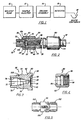
- Cartridge column assembly 20 includes a generally cylindrically shaped column 22 containing an axial bore 24 and made of a material which is not corroded by typical liquid chromatography solvents. Disposed within the central bore 24 of the column 22 is a particulate packing material 26, the exact nature of which is not germane to the present invention but is well known in the art.
- the central bore 24 has an enlarged counterbore as illustrated at 28 to provide a recess designed to receive a frit 30 which is press fitted or otherwise secured therein by any suitable mechanical retaining means.
- Frit 30 retains the particulate matter 26 within the central bore 24 and also diffuses the incoming mobile phase. Frit 30, made of a conventional material, has a greater porosity than does the packing 26. Consequently, liquid passing through the system can pass more easily through frit 30 than it can through packing material 26.
- the column coupling assembly includes a generally hollow cylindrical coupler member 32, shown in enlarged detail in Fig. 3. At one end, member 32 has a cylindrical portion 34 carrying a radially outwardly extending coaxial annular flange 60. At the end remote from flange 60, coupler member 32 has a cylindrical portion 70 coaxial with and of smaller diameter than cylindrical portion 34. In operative assembly coupler member 32 is positioned in coaxial abutment with the end of column 22 so that the axis of the cylindrical portion 34 is coincident with the axis of cartridge column 20.
- the face 36 of flange 60 contains a concentric annular groove 40 in which is disposed an annular gasket member 42 (Fig. 1).
- Groove 40 is radially dimensioned so that it is in apposition to the end of column 22 and the outermost region of frit 30.
- a gasket member 42 disposed within the annular groove 40 is a gasket member 42 made of a perfluoroelastomer such as "KAL- REZ NO. 1050" manufactured by Dupont, although a suitable gasket can be made from other similar materials. Alternate types of material should have compression characteristic similar to KAL-REZ NO. 1050 and be chemically inert in the solvents used in liquid chromatography.
- the gasket 42 is preferably press fitted into the groove 40, although a portion of the gasket 42 when fully inserted into the groove 40 projects out of the groove 40 in a direction facing toward the column 20.
- groove 40 has a depth of .025 inches below face 36 and the gasket has a thickness of .030 inches. Accordingly, in its uncompressed state, gasket 42 extends .0005 inches to the right, as viewed in Fig. 2, of the face 36 of flange 60 of coupling member 32. This permits column 20 to be pressed in a direction toward the cylindrical portion 34 to thereby compress the gasket 42 and provide a fluid tight seal between the two members at typical liquid chromatography pressures.
- gasket 42 is made by a die punching process from a sheet of the perfluoroelastomer material which has a thickness substantially identical to that of the desired annular gasket.
- the plane of the central face portion 46 of the coupler member 32 is recessed from the plane of the face 36 in its preferred embodiment by from about .005 inch to about .007 inch. This recess is provided to ensure that a small gap will be formed between central face portion 46 and frit 30 when cartridge column 20 is pressed against coupler member 32 at which time gasket 42 is compressed so that its protrusion beyond face 36 is considerably reduced from its uncompressed state.
- This small gap forms a chamber or sample distribution cavity 48 between frit 30 and face portion 46, thereby providing a channel for liquid being pumped through the column to pass through between a central bore 50 and frit 30 in a substantially uniform manner.
- a further advantage of having cavity 48 is that frit 30, which acts as a filter in this case, does not easily become subject to plugging caused by particulate and other foreign matter in the liquid being pumped through the column. By evenly distributing the liquid entering as well as leaving packing 26 over the entire surface of frit 30, the plugging problem is substantially reduced.
- coupler member 32 illustrated in axial section, includes the cylindrical portion 34 described in conjunction with Fig. 2. This cylindrical portion 34 is disposed in Fig. 3 to the left of a radially extending flange 60, which has a back face 62. In the final assembly of the fitting according to the present invention, coupler member 32 is arranged to remain substantially rotationally stationary while remaining coupled to a collar member 80, which encircles coupler member 32 in a manner to be described hereinafter in greater detail.
- Coupler member 32 includes a second cylindrical portion 70 disposed to the left of cylindrical portion 34, as seen in Fig. 3.
- Cylindrical portion 70 preferably is provided with two parallel flats suitable for engagement by a wrench, thereby permitting coupler 32 to be tightened onto an externally threaded supply pipe or the like (not shown), which is inserted into internally threaded bore 72.
- tools may be required for the attachment of coupler member 32 to a supply pipe but not for decoupling and changing the column. While a threaded connection is shown and described, it should be noted that other conventional forms of attachment may be used to couple a pipe to the inner surface of the bore 72.
- the inner surface of the bore 72 in the region indicated at 76 gradually tapers inwardly in the direction of end face 46 until it merges with central bore 50.
- the specific configuration of this portion of the coupler member is not particularly critical and may take any suitable alternative physical design desired.
- the shape conforms to a 1/16" chemical processing industrial connector and central bore 50 is preferably of a diameter which is approximately the same as the central fluid carrying bore of the inlet or outlet tube which is to be mounted in the coupler member.
- Bore 50 is of a diameter and a length such as to not adversely affect the chromatographic analysis to be performed.
- coupler member 32 is made of a titanium alloy which does not corrode in the presence of typical liquid chromatography solvents.
- a typical diameter of cylindrical portion 34 of coupler member 32 is .300 inches.
- collar member 80 of the fitting of the present invention is shown in axial section.
- Collar member 80 has an outer surface indicated generally at 82, which is suitably grooved or knurled so it may easily be grasped with an operator's hand.
- Collar member 80 is provided with a radially inwardly extending annular flange 84 which coacts with the mating radially outwardly extending flange 60 to connect coupling member 32 to cartridge column 20, as will be discussed more fully hereinafter. Extending to the right of flange 84, as viewed in Fig.
- Fig. 4 is a cylindrically shaped portion indicated generally at 96, which includes an internally threaded section 98 for coupling to an externally threaded section 102 of housing 99 (Fig. 5), which is adapted to encircle column 22, as best seen in Fig. 2.
- housing 99 comprises a cylindrical body 100 having external threading 102 at each end for engagement with respective collar members 80.
- the housing can be made of any suitable material capable of withstanding the mechanical stresses placed thereon and, because it does not come in direct contact with the liquid chromatography solvents, it need not necessarily be made of a material which is corrosion resistant to such solvents.
- coupler members 32 In a normal assembly operation threaded portions 72 of coupler members 32 are connected to the sample injector and the detector, respectively.
- One end of the cartridge column housing 99 is connected to one collar member 80 by screw threads 98 and mating screw threads 102.
- Cartridge column 20 is inserted into the housing and the other collar member is connected to the other end of the housing. Both collar members are rotated until the gaskets 42 engage the frits 30 at the cartridge column ends, respectively.
- a ring or bushing 104, Fig. 2 is interposed between each flange 84 and corresponding flange 60.
- the ring has a low coefficient of friction to facilitate the rotational movement between the respective collars 80 and coupler members 32 during assembly.
- a preferred material for the ring is Delrin.
- a high pressure liquid seal is effected by twisting collar members 80 by hand in opposite directions until a strong resistance is felt.
- collar members 80 are locked in position with respect to the associated coupler members 32 by the insertion of a Waldes "E" ring 106, or equivalent, in annular slots 108 (as shown in Fig. 3) provided for the purpose in coupler members 32.
- a Waldes "E" ring 106 or equivalent, in annular slots 108 (as shown in Fig. 3) provided for the purpose in coupler members 32.
- abrasion between gasket members 42 and the ends of the cartridge column is minimized. It has been found that such hand tightening of the collar members exerts sufficient compression on the gasket as to provide a system which withstands pressures in excess of about 15,000 to about 20,000 pounds per square inch.
- this new and improved assembly eliminates the necessity of disconnecting either the sample injector or the detector when changing columns. As described, an assembly according to the present invention makes it possible to change columns easily without the use of
Applications Claiming Priority (2)
| Application Number | Priority Date | Filing Date | Title |
|---|---|---|---|
| US15539488A | 1988-02-12 | 1988-02-12 | |
| US155394 | 1999-09-22 |
Publications (3)
| Publication Number | Publication Date |
|---|---|
| EP0328146A2 true EP0328146A2 (fr) | 1989-08-16 |
| EP0328146A3 EP0328146A3 (fr) | 1991-08-21 |
| EP0328146B1 EP0328146B1 (fr) | 1995-09-20 |
Family
ID=22555247
Family Applications (1)
| Application Number | Title | Priority Date | Filing Date |
|---|---|---|---|
| EP19890102368 Expired - Lifetime EP0328146B1 (fr) | 1988-02-12 | 1989-02-10 | Colonne pour chromatographie liquide à haute pression |
Country Status (2)
| Country | Link |
|---|---|
| EP (1) | EP0328146B1 (fr) |
| DE (1) | DE68924284T2 (fr) |
Cited By (7)
| Publication number | Priority date | Publication date | Assignee | Title |
|---|---|---|---|---|
| EP0600213A1 (fr) * | 1992-10-30 | 1994-06-08 | E.I. Du Pont De Nemours And Company | Système portable surplace de chromatographie de liquide |
| EP0779512A1 (fr) * | 1995-12-14 | 1997-06-18 | Hewlett-Packard Company | Colonne pour des séparations chromatographiques capillaires |
| US6464882B1 (en) | 1998-03-19 | 2002-10-15 | Prior Separation Technology Gmbh | Annular chromatograph |
| GB2429939A (en) * | 2005-09-13 | 2007-03-14 | Agilent Technologies Inc | Liquid chromatography column having metal to metal seals |
| WO2008121453A2 (fr) | 2007-02-22 | 2008-10-09 | Waters Investments Limited | Dispositif, appareil, et procédés pour effectuer des séparations |
| EP2823295A4 (fr) * | 2012-03-05 | 2015-11-04 | Waters Technologies Corp | Protection anticorrosion dans une tubulure utilisée en chromatographie |
| CN115569674A (zh) * | 2022-09-29 | 2023-01-06 | 中国科学院地球环境研究所 | 一种可快速安装与拆卸的离子交换色谱柱 |
Citations (6)
| Publication number | Priority date | Publication date | Assignee | Title |
|---|---|---|---|---|
| US3682315A (en) * | 1969-10-20 | 1972-08-08 | Wolfgang Haller | Cartridge type column for treatment of liquid streams and substrate enclosure therefor |
| US3855130A (en) * | 1971-12-07 | 1974-12-17 | Merck Patent Gmbh | Column for pressure chromatography |
| US3904527A (en) * | 1975-02-18 | 1975-09-09 | Instrumentation Specialties Co | Chromatographic column |
| DE2945180A1 (de) * | 1978-11-22 | 1980-05-29 | Shoji Prof Hara | Hochdruckglaskolonne fuer die hochleistungs-fluessigchromatographie |
| EP0205002A1 (fr) * | 1985-06-01 | 1986-12-17 | MERCK PATENT GmbH | Colonne chromatographique |
| JPS62138751A (ja) * | 1985-12-13 | 1987-06-22 | Hitachi Ltd | 液体クロマトグラフ用カラム |
-
1989
- 1989-02-10 DE DE1989624284 patent/DE68924284T2/de not_active Expired - Fee Related
- 1989-02-10 EP EP19890102368 patent/EP0328146B1/fr not_active Expired - Lifetime
Patent Citations (6)
| Publication number | Priority date | Publication date | Assignee | Title |
|---|---|---|---|---|
| US3682315A (en) * | 1969-10-20 | 1972-08-08 | Wolfgang Haller | Cartridge type column for treatment of liquid streams and substrate enclosure therefor |
| US3855130A (en) * | 1971-12-07 | 1974-12-17 | Merck Patent Gmbh | Column for pressure chromatography |
| US3904527A (en) * | 1975-02-18 | 1975-09-09 | Instrumentation Specialties Co | Chromatographic column |
| DE2945180A1 (de) * | 1978-11-22 | 1980-05-29 | Shoji Prof Hara | Hochdruckglaskolonne fuer die hochleistungs-fluessigchromatographie |
| EP0205002A1 (fr) * | 1985-06-01 | 1986-12-17 | MERCK PATENT GmbH | Colonne chromatographique |
| JPS62138751A (ja) * | 1985-12-13 | 1987-06-22 | Hitachi Ltd | 液体クロマトグラフ用カラム |
Non-Patent Citations (1)
| Title |
|---|
| PATENT ABSTRACTS OF JAPAN, vol. 11, no. 366 (P-641)[2813], 28th November 1987; & JP-A-62 138 751 (HATACHI) 22-06-1987 * |
Cited By (14)
| Publication number | Priority date | Publication date | Assignee | Title |
|---|---|---|---|---|
| EP0600213A1 (fr) * | 1992-10-30 | 1994-06-08 | E.I. Du Pont De Nemours And Company | Système portable surplace de chromatographie de liquide |
| EP0779512A1 (fr) * | 1995-12-14 | 1997-06-18 | Hewlett-Packard Company | Colonne pour des séparations chromatographiques capillaires |
| US5908552A (en) * | 1995-12-14 | 1999-06-01 | Hewlett-Packard Company | Column for capillary chromatographic separations |
| US6464882B1 (en) | 1998-03-19 | 2002-10-15 | Prior Separation Technology Gmbh | Annular chromatograph |
| GB2429939A (en) * | 2005-09-13 | 2007-03-14 | Agilent Technologies Inc | Liquid chromatography column having metal to metal seals |
| EP2148733A2 (fr) * | 2007-02-22 | 2010-02-03 | Waters Investments Limited | Dispositif, appareil, et procédés pour effectuer des séparations |
| WO2008121453A2 (fr) | 2007-02-22 | 2008-10-09 | Waters Investments Limited | Dispositif, appareil, et procédés pour effectuer des séparations |
| JP2010519546A (ja) * | 2007-02-22 | 2010-06-03 | ウオーターズ・テクノロジーズ・コーポレイシヨン | 分離を実行するための装置、機器、及び、方法 |
| EP2148733A4 (fr) * | 2007-02-22 | 2012-01-04 | Waters Technologies Corp | Dispositif, appareil, et procédés pour effectuer des séparations |
| US8449769B2 (en) | 2007-02-22 | 2013-05-28 | Waters Technologies Corporation | Device, apparatus and method for performing separations |
| US9724621B2 (en) | 2007-02-22 | 2017-08-08 | Waters Technologies Corporation | Device, apparatus and method for performing separations |
| EP2823295A4 (fr) * | 2012-03-05 | 2015-11-04 | Waters Technologies Corp | Protection anticorrosion dans une tubulure utilisée en chromatographie |
| US10232287B2 (en) | 2012-03-05 | 2019-03-19 | Waters Technologies Corporation | Corrosion protection in tubing used chromatography |
| CN115569674A (zh) * | 2022-09-29 | 2023-01-06 | 中国科学院地球环境研究所 | 一种可快速安装与拆卸的离子交换色谱柱 |
Also Published As
| Publication number | Publication date |
|---|---|
| DE68924284T2 (de) | 1996-02-29 |
| EP0328146B1 (fr) | 1995-09-20 |
| DE68924284D1 (de) | 1995-10-26 |
| EP0328146A3 (fr) | 1991-08-21 |
Similar Documents
| Publication | Publication Date | Title |
|---|---|---|
| US4876005A (en) | High pressure column assembly for a liquid chromatograph system | |
| US4313828A (en) | High pressure tubing coupler | |
| US5482628A (en) | Column for liquid chromatography | |
| US5730943A (en) | Integral fitting and filter of an analytical chemical instrument | |
| US4565632A (en) | Chromatographic cartridge column system | |
| US8569070B2 (en) | Connection assembly for ultra high pressure liquid chromatography | |
| US8696902B2 (en) | High pressure connect fitting | |
| JP4909897B2 (ja) | 分離を実施するデバイス、方法、および装置 | |
| US9151734B2 (en) | Connection assembly for ultra high pressure liquid chromatography | |
| US9188569B2 (en) | High pressure fitting with self-releasing ferrule | |
| EP0884081A2 (fr) | Raccord integral et filtre | |
| USRE31974E (en) | Cartridge type separation column and holder assembly for liquid chromatographs | |
| US8931808B2 (en) | High pressure fitting with self-releasing ferrule | |
| US11137378B2 (en) | Quick lock connector for connecting a capillary to a fluidic conduit of a fluidic component | |
| US8696038B2 (en) | Flat bottom fitting assembly | |
| US10422452B2 (en) | High pressure fluidic connection assemblies | |
| EP0328146B1 (fr) | Colonne pour chromatographie liquide à haute pression | |
| GB2482488A (en) | Fitting coupler for planar fluid conduit | |
| US4162977A (en) | Means for removably securing separation column within column chromatography apparatus | |
| US5062706A (en) | High pressure fluid sample flow cell with circumferential window edge seal | |
| WO2011061769A1 (fr) | Dispositifs de support pour colonnes capillaires et nano-colonnes de clhp | |
| CN211426395U (zh) | 零死体积液体高压开关阀 | |
| US20210339166A1 (en) | Seal for separation device | |
| JPH06242094A (ja) | 液体クロマトグラフ用フィルター内蔵カラム |
Legal Events
| Date | Code | Title | Description |
|---|---|---|---|
| PUAI | Public reference made under article 153(3) epc to a published international application that has entered the european phase |
Free format text: ORIGINAL CODE: 0009012 |
|
| AK | Designated contracting states |
Kind code of ref document: A2 Designated state(s): DE GB |
|
| PUAL | Search report despatched |
Free format text: ORIGINAL CODE: 0009013 |
|
| AK | Designated contracting states |
Kind code of ref document: A3 Designated state(s): DE GB |
|
| 17P | Request for examination filed |
Effective date: 19920221 |
|
| 17Q | First examination report despatched |
Effective date: 19930902 |
|
| GRAA | (expected) grant |
Free format text: ORIGINAL CODE: 0009210 |
|
| AK | Designated contracting states |
Kind code of ref document: B1 Designated state(s): DE GB |
|
| REF | Corresponds to: |
Ref document number: 68924284 Country of ref document: DE Date of ref document: 19951026 |
|
| PLBE | No opposition filed within time limit |
Free format text: ORIGINAL CODE: 0009261 |
|
| STAA | Information on the status of an ep patent application or granted ep patent |
Free format text: STATUS: NO OPPOSITION FILED WITHIN TIME LIMIT |
|
| 26N | No opposition filed | ||
| REG | Reference to a national code |
Ref country code: GB Ref legal event code: 732E |
|
| REG | Reference to a national code |
Ref country code: GB Ref legal event code: IF02 |
|
| PGFP | Annual fee paid to national office [announced via postgrant information from national office to epo] |
Ref country code: DE Payment date: 20020205 Year of fee payment: 14 |
|
| PGFP | Annual fee paid to national office [announced via postgrant information from national office to epo] |
Ref country code: GB Payment date: 20020212 Year of fee payment: 14 |
|
| PG25 | Lapsed in a contracting state [announced via postgrant information from national office to epo] |
Ref country code: GB Free format text: LAPSE BECAUSE OF NON-PAYMENT OF DUE FEES Effective date: 20030210 |
|
| PG25 | Lapsed in a contracting state [announced via postgrant information from national office to epo] |
Ref country code: DE Free format text: LAPSE BECAUSE OF NON-PAYMENT OF DUE FEES Effective date: 20030902 |
|
| GBPC | Gb: european patent ceased through non-payment of renewal fee |