EP0328093A2 - Gray code converter giving a fault signal - Google Patents
Gray code converter giving a fault signal Download PDFInfo
- Publication number
- EP0328093A2 EP0328093A2 EP89102218A EP89102218A EP0328093A2 EP 0328093 A2 EP0328093 A2 EP 0328093A2 EP 89102218 A EP89102218 A EP 89102218A EP 89102218 A EP89102218 A EP 89102218A EP 0328093 A2 EP0328093 A2 EP 0328093A2
- Authority
- EP
- European Patent Office
- Prior art keywords
- signals
- signal
- gray code
- switching mechanism
- register
- Prior art date
- Legal status (The legal status is an assumption and is not a legal conclusion. Google has not performed a legal analysis and makes no representation as to the accuracy of the status listed.)
- Withdrawn
Links
- 230000007246 mechanism Effects 0.000 claims abstract description 35
- 238000000034 method Methods 0.000 claims abstract description 24
- 238000005259 measurement Methods 0.000 claims description 22
- 230000008859 change Effects 0.000 claims description 17
- 238000012546 transfer Methods 0.000 claims description 11
- 230000001360 synchronised effect Effects 0.000 claims description 5
- 238000012545 processing Methods 0.000 claims description 3
- 238000001514 detection method Methods 0.000 claims 2
- 238000006243 chemical reaction Methods 0.000 claims 1
- 230000008569 process Effects 0.000 abstract description 6
- 238000013461 design Methods 0.000 abstract description 2
- 230000005693 optoelectronics Effects 0.000 abstract description 2
- 230000007704 transition Effects 0.000 description 24
- 238000010586 diagram Methods 0.000 description 4
- 230000007257 malfunction Effects 0.000 description 4
- 230000003321 amplification Effects 0.000 description 2
- 230000008901 benefit Effects 0.000 description 2
- 238000003199 nucleic acid amplification method Methods 0.000 description 2
- 238000005070 sampling Methods 0.000 description 2
- 238000007493 shaping process Methods 0.000 description 2
- 230000001960 triggered effect Effects 0.000 description 2
- 241000167880 Hirundinidae Species 0.000 description 1
- 108010076504 Protein Sorting Signals Proteins 0.000 description 1
- 230000015572 biosynthetic process Effects 0.000 description 1
- 238000004891 communication Methods 0.000 description 1
- 230000001934 delay Effects 0.000 description 1
- 230000003111 delayed effect Effects 0.000 description 1
- 230000001419 dependent effect Effects 0.000 description 1
- 230000000694 effects Effects 0.000 description 1
- 238000005516 engineering process Methods 0.000 description 1
- 238000011156 evaluation Methods 0.000 description 1
- 230000007274 generation of a signal involved in cell-cell signaling Effects 0.000 description 1
- 230000001771 impaired effect Effects 0.000 description 1
- 238000012905 input function Methods 0.000 description 1
- 230000003287 optical effect Effects 0.000 description 1
- 230000033764 rhythmic process Effects 0.000 description 1
- 230000003068 static effect Effects 0.000 description 1
- 238000011144 upstream manufacturing Methods 0.000 description 1
Images

Classifications
-
- G—PHYSICS
- G01—MEASURING; TESTING
- G01D—MEASURING NOT SPECIALLY ADAPTED FOR A SPECIFIC VARIABLE; ARRANGEMENTS FOR MEASURING TWO OR MORE VARIABLES NOT COVERED IN A SINGLE OTHER SUBCLASS; TARIFF METERING APPARATUS; MEASURING OR TESTING NOT OTHERWISE PROVIDED FOR
- G01D5/00—Mechanical means for transferring the output of a sensing member; Means for converting the output of a sensing member to another variable where the form or nature of the sensing member does not constrain the means for converting; Transducers not specially adapted for a specific variable
- G01D5/12—Mechanical means for transferring the output of a sensing member; Means for converting the output of a sensing member to another variable where the form or nature of the sensing member does not constrain the means for converting; Transducers not specially adapted for a specific variable using electric or magnetic means
- G01D5/244—Mechanical means for transferring the output of a sensing member; Means for converting the output of a sensing member to another variable where the form or nature of the sensing member does not constrain the means for converting; Transducers not specially adapted for a specific variable using electric or magnetic means influencing characteristics of pulses or pulse trains; generating pulses or pulse trains
- G01D5/249—Mechanical means for transferring the output of a sensing member; Means for converting the output of a sensing member to another variable where the form or nature of the sensing member does not constrain the means for converting; Transducers not specially adapted for a specific variable using electric or magnetic means influencing characteristics of pulses or pulse trains; generating pulses or pulse trains using pulse code
- G01D5/2492—Pulse stream
-
- H—ELECTRICITY
- H03—ELECTRONIC CIRCUITRY
- H03M—CODING; DECODING; CODE CONVERSION IN GENERAL
- H03M1/00—Analogue/digital conversion; Digital/analogue conversion
- H03M1/12—Analogue/digital converters
- H03M1/22—Analogue/digital converters pattern-reading type
- H03M1/24—Analogue/digital converters pattern-reading type using relatively movable reader and disc or strip
- H03M1/28—Analogue/digital converters pattern-reading type using relatively movable reader and disc or strip with non-weighted coding
- H03M1/285—Analogue/digital converters pattern-reading type using relatively movable reader and disc or strip with non-weighted coding of the unit Hamming distance type, e.g. Gray code
-
- H—ELECTRICITY
- H03—ELECTRONIC CIRCUITRY
- H03M—CODING; DECODING; CODE CONVERSION IN GENERAL
- H03M13/00—Coding, decoding or code conversion, for error detection or error correction; Coding theory basic assumptions; Coding bounds; Error probability evaluation methods; Channel models; Simulation or testing of codes
Definitions
- the invention relates to a method and a circuit arrangement for converting Gray code signals into counting pulses and for forming a counter reading, for detecting interference signals violating Gray code and for forming an error signal.
- Gray code signals are often obtained from precision scans in precision dimension measuring machines via the intermediate stage of sine and cosine signals, transmitted to an evaluation device and processed there as a measurement result via a counter to give a coordinate.
- interference signals for example electromagnetically coupled from the environment.
- Interference signals that deviate significantly from the measurement signals with their time profile, in particular form shorter pulses, can be filtered out. This is carried out with the HCTL 2000 quadrature decoder from Hewlett Packard (Technical Data April 1986).
- Interference signals with a time behavior similar to the measurement signals on only one input line are generally not a problem if they simulate an up and a down counting event with their switch-on and switch-off edges, which results in zero in total and therefore remains ineffective.
- Signals that are only impressed on one input line can also lead to a Gray code violation if they coincide with one of their signal edges with an edge of a measurement signal on another line.
- the up and down counting pulses are also not reliably separated in time, which can result in malfunctions of the counter.
- Gray code violations are also possible due to interference signals on only one signal line if an edge of an interference signal coincides with the edge of a measurement signal on another line.
- the invention has for its object to limit the number of error messages to the necessary extent.
- Known generic circuit arrangements are simply to be substituted.
- the advantages achieved by the invention are, in particular, that the interruptions in measurement sequences are reduced to a minimum by error messages.
- the invention can take the place of previously known generic circuit arrangements without requiring changes to the upstream or downstream functional elements.
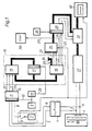
- 1 shows a known, for example optoelectronic, scale scanning device 1, which outputs a sinX-proportional output signal 2 and a cosX-proportional output signal 3 depending on the X position of an object.
- two square-wave logic signals 5,6 are generated from the two sinX and cosX proportional signals 2, 3, which are phase-shifted by 90 ° relative to one another, and which occur at each zero crossing of the sinX or cosX signal 2 , 3 have a signal edge or level change.
- the pair of square-wave logic signals 5, 6 represent gray code signals, since at most one signal 5 or 6 has a signal edge.
- a reset signal 8 can be triggered by a switching device 7.
- a clock generator 9 generates a clock signal 10 with a specific clock frequency.
- the two square-wave logic signals 5, 6 and the reset signal 8 are applied to the inputs of a register 11, which is controlled by the clock signal 10.
- the pending at a time determined by the clock signal 10 t0 at the inputs of the register 11 level of the signals 5,6 and 8 are switched through to the outputs of the register and held during the time interval until the next clock signal 10 at a time t 1, at which time the levels pending at time t 1 are switched through.
- the register 11 thus forms the gray code output signals 12 and 13 from the two input signals 5 and 6 and the reset output signal 14 from the reset input signal 8.
- the output signals 12, 13 and 14 are synchronized with the clock signal 10 and are always fixed for a fixed time interval.
- the synchronized output signals 12, 13 and 14 are connected to the inputs of a clocked switching mechanism 15, which in this example is based on the model of a Moore machine and consists of a transfer switching network 16, a register 17 and out an output switching network 18.
- the Moore automaton is determined by this (Steinbuch, Rupprecht, ed .: sympathetic activator, ed .: sympathetic activator, a rotary switch, or the like.
- the outputs of the transfer switching network 16 are not only fed to the output switching network 18 via the register 17, but are also fed back to inputs of the transfer switching network 16.
- the register 17 is controlled by the clock generator 9 via a delay element 19 with a clock signal 20 which has the same frequency as the clock signal 10 but is delayed taking into account the signal propagation times in the elements 11, 16 and 17. It is possible and implemented in the example that the output switching network 18 as a trivial unit switching network, i. H. to be implemented as a direct through connection from input to output.
- the output switching network 18 therefore contains no components and can therefore not cause any faults. All links must therefore be combined in the transfer switching network 16.
- switchgears and automats are known from communications technology (Steinbach, Rupprecht, d. 0.) And are explained in more detail below for the application in this example with reference to FIG. 2.
- the clocked switching mechanism 15 delivers two counting pulses 21 and 22 and an error signal 23 as the output signal.
- the counting pulses 21, 22 are implemented as down (21) and up (22) counting signals.
- the error signal 23 is fed to an error reporting device 28.
- this error reporting device 28 can also take over automatic functions such as the abort of a measurement process, a new start from a defined initial position, and the reset signal 8 being triggered.
- the outputs of the counter 26 and the counter status signals 24 and 25 are fed to a register 29 which is controlled by a further clock generator 30.
- the output signals of the register 29 and the fine interpolator 27 are fed to a synchronization device 31, which forms the final measured value from the input signals and feeds them to an output unit 32 via their output signals.
- the output unit 32 can be a display for the operator in the simplest case, but usually also includes the transfer to automatic storage and computing systems.
- the switching mechanism 15, the counter 26 and the output 32 can be brought into a basic position by the reset signal 8.
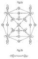
- FIG. 2 shows the state transition graph of a Moore automaton as a model for the clocked switching mechanism 15 in FIG. 1, the automaton generating the error signal 23 under the conditions according to the invention and acting as a quadruple interpolator, ie for every level change of the input signals 12 and 13 and thus generates a counting pulse 21 (down) or 22 (up) four times per period of the sinX signal 2.
- the machine has 20 states S1 to S20, which are characterized by the combination of the logical values of signals 21 to 25 and other internal signals (e.g. 33.34). All input (12 to 14) and status signals (21 to 25, 33, 34) are square-wave signals, one level of which is assigned the logical "1" and the other level of which is the logical "0".
- the state transition graph is divided into two parts (FIGS. 2a and 2b).
- 2a shows the partial state transition graph for the 18 states S3 to S20.
- the states of the machine are represented by circles.
- the state S3 is shown six times. This allows a clear two-dimensional representation. Arrows indicate transitions between the states.
- the transition from the Si state takes place along one of these through the transition into the time interval N + 1 Combination of 12, 13 and 14 specific arrow to a state Sj.
- State S3 is the basic state. It is reached from states S5 to S8 and S17 to S20 when the input signal 14, the reset signal, is activated.
- State S4 controls the transitions between states S1 and S2 in FIG. 2b and thus the error message at error output 23.
- S4 can be reached from states S17 to S20 and always changes to the basic state S3.
- S5 to S8 are idle states. They are distinguished from one another by signals 24 and 25.
- the states S9 to S16 lie in the state transition graph between idle states S5 to S8; they are always reached from an idle state S5 to S8 and change again to an idle state S5 to S8 in the next time interval of the clock cycle 20.
- a count pulse 21, 22 is generated by this sequence.
- Four of the states S9 to S16 are up and down count pulse generators.
- the states S17 to S20 are reached from the idle states S5 to S8 when the input signals 12 and 13 have a Gray code error. If only one of the input signals 12 or 13 changes in a subsequent time interval of the clock cycle 20, the states S17 to S20 change to the state S4. This causes an error message below. Without changing the input signals 12 and 13, the state S17 to S20 remains. When both input signals 12 and 13 change, the automaton falls back into the previous idle state S5 to S8, thereby avoiding unnecessary error messages.
- 2b shows the partial state transition graph for the states S1 and S2 "error status set" in the same representation.
- the states are identified by signal 23.
- state S2 signal 23 is activated and the error message is thus output.
- the transition from state S1 to state S2 takes place when state S4 is reached in the partial state transition graph FIG. 2a.
- the state S1 is reached from the state S2 when the reset signal 14 is activated.
- the two signals 5 and 6 together show four signal edges. This is also the case after the synchronization in register 11 for signals 12 and 13.
- the signal edge repetition frequency at the inputs of the clocked switching mechanism 15 is therefore four times the signal frequency of 5 or 6.
- a counting event (for example S8-S12-S7) requires two transitions, that is to say two time intervals of the clock pulse 20. Therefore the clock frequency of the clock pulse 20 and thus also the time cycle 10 - be at least eight times the largest signal frequency.
- the shortest pulse duration of an interference signal on the signal inputs 12 or 13 of the switching mechanism 15 is just equal to a time interval of the timing clock 10 or 20 through the register 11.
- the clock frequency of the clock 10 or 20 is selected at least 20 times as large as the signal frequency, so that there are at least five time intervals of the clock 10 and 20 between every two edges of the measurement signals on the signal lines 12 and 13.
- a single interference pulse on a line 12 or 13 can lead to an up and down counting pulse pair 22 and 21 with the sum zero and a double gray code violation can also be detected. Most of the malfunctions can thus be processed harmlessly.
- the maximum permissible clock frequency of the clock cycle 10 or 20 is determined by the maximum signal propagation times in the switching elements 11, 16 to 18 or 47 to 50 and 26.
- the design of the state transition graph (FIG. 2) which requires at least two transitions and thus time intervals of the clock cycle 20 per count pulse 21 or 22, also has the advantage that the count pulses 21 or 22 with their duration of one time interval of the clock cycle 20 never can follow one another without a pause, so that malfunctions of the counter 26 are avoided.
- FIG. 3 shows a signal state diagram which shows, by way of example, the chronological sequence of the input signals 12 and 13 and the states S4 to S20 controlled thereby for the Moore automaton according to the state transition graph in FIG. 2.
- the states S1 and S2 (FIG. 2b) are not directly influenced by the input signals 12 and 13, as is the basic state S3, which is reached from S4 or by the reset signal 14.
- 3a shows an example of an undisturbed signal sequence.
- the clock frequency is twenty times the maximum signal frequency and this is fully utilized, i. H.
- An input signal 12 or 13 changes after every five time intervals of the time cycle.
- the clock cycle 10 the input signals 12 and 13, the states Si from S4 to S20, their meaning and the counter reading of the counter 26 are shown one above the other.
- the states Si are assumed in the real switching mechanism 15 in the rhythm of the timing clock 20, which is phase-shifted against the timing clock 10 of the register 11 and the input signals 12 and 13.
- the meaning of the states Si is indicated by arrows for the generation of the up (22) and down (21) counting pulses.
- An exclamation mark identifies the states S17 to S20 that are reached when the input signals 12 and 13 have a Gray code error.
- 3b shows examples of interference pulses which occur simultaneously on both input signals 12 and 13. Regardless of the polarity of the interference pulses, the counting is not impaired in Examples 35 and 36, the first Gray code violation leads to states S17 and S20 and the following second Gray code violation leads back to an idle state S5 and S7 .
- Example 37 This is different in Example 37, where the interference pulse in the input signal 12 "swallows" a measurement signal change. As a result, the leading edge of the interference pulse on the input signal 12 is also not recognizable. The leading edge of the glitch on the input signal 13 therefore causes an incorrect down count. Only the trailing edge of the interference pulse occurs on both input signals 12 and 13, this gray code violation causes the transition to state S17. The next change in the measurement signal does not result in a gray code violation, and so the transition takes place to state S4 "report gray code error” and subsequently to S2 "error status set", where error signal 23 is activated, and to basic state S3.
- Fig. 3c shows an example of the fact that interference pulses on only one input signal 12 or 13 can lead to Gray code violations.
- leading and trailing edges of the interference pulse on the input signal 13 coincide with two measuring signal edges on the input signal 12.
- Even without an interference pulse the two edges of the measurement signal on the input signal 12 would not have resulted in a total count, since an up and a down counter event cancel each other out.
- an interference pulse has its leading edge at the same time as the edge of a measurement signal on the other input signal 13. This gray code error causes the transition to state S17. With the trailing edge of the interference pulse, only one input signal 12 changes and therefore the transition from state S17 to state S4 "report gray code error" takes place.
- the states of the machine are u. a. determined by signals 24 and 25. It has already been shown above that these signals 24 and 25 can also be routed as an option to the output of the clocked switching mechanism 15 in order to synchronize a fine interpolator 27 with the quadruple interpolator.
- a counting process of the clocked switching mechanism 15, which is designed as a quadruple interpolator always goes from a subsequent state (for example S7) to a counting pulse generator state (for example S13) and further to a next subsequent state (for example S5). leads, the changed up or down count signal 21 or 22 is reset. Synchronously with this, one of the signals 24 or 25 changes its level.
- Signals 24 and 25 thus form a 2-bit Gray code counter, which is used internally to distinguish between the subsequent states S5 to S8. Their logical value indicates the quadrant of the sinX and cosX input functions 2 and 3 of the quadruple interpolator. Their use for the synchronization of a fine interpolation device is described below.
- FIG. 4 shows how, for example, in the case of a sampling 42 (clock signal 10) which occurs immediately after a zero crossing 41 of the sinX (t) signal 2 because of the necessary hysteresis 43 of a sine comparator of the amplification and pulse shaping circuit 4, the level change 44 of the square wave Logic signal 5 is not yet generated. Until a counting pulse 45 is generated on one of the up / down counting pulse lines 21, 22 and the count in the counter 26, there are further delays in the elements 11, 15 and 26 (FIG. 1).
- the fine interpolation device 27 already works in the quadrant of the sinX (t) function following the zero crossing 41 (signal 2).
- ⁇ 1 the fine interpolation device 27
- the information for correcting the counter reading is taken from the two least significant bits of the counter reading of the counter (corresponding to FIG. 26).
- the assignment of these bits to the quadrants of the sinX (t) function 2 must first be obtained by a synchronization process in which the measuring machine runs very slowly after being switched on until a first counting pulse (21 or 22) and counter reading are generated and this counter reading is assigned to quadrants recognized in the fine interpolation device 27, or until the area of the hysteresis 43 is safely left and the counter 26 is loaded in accordance with the quadrant recognized in the fine interpolation device.
- the synchronization in the synchronization device 31 is achieved directly and the problems of the known method are eliminated.
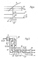
- FIG. 5 shows a circuit arrangement according to the invention based on the model of a Mealy automaton as a further example.
- gray code square-wave signals 5, 6 and 8 in the register 11 are synchronized with the clock signal 10 and then provided as signals 12, 13 and 14. These are now processed by the clocked switching mechanism 46, which consists of a transfer switching network 47, a register 48 and an output switching network 49.
- the outputs 51 to 55 of the clocked switching mechanism 46 are connected to a register 50.
- the register 50 is controlled by a clock signal 56 with the frequency of the clock signals 10 and 20.
- the same signals 21 to 25 are available at the outputs of the register 50 as at the outputs of the clocked switching mechanism 15 based on the Moore automaton model (FIG. 1).
- the switching mechanism 46 differs from the switching mechanism 15 in FIG. 1 in that the output switching network 49 is also connected directly to the input signals 12 to 14.
- the switching mechanism 46 is characterized as a technical implementation of a Mealy machine (Steinbuch, Rupprecht, loc. Cit.).
- the output switching network 49 Since the output switching network 49 is connected not only to signals 57 which arise as the output of the register 48, but also directly to the input signals 12, 13 and 14, the output switching network 49 cannot be a trivial unit switching network like the output switching network 18 in Fig. 1 can be realized.
- the circuit arrangement with a clocked switching mechanism 46 based on the model of a Mealy automaton is therefore more complex with the output switching network 49 and the register 50 than the circuit shown in FIG. 1 with the switching mechanism 15 based on the model of a Moore automaton.
- the state transition graph which defines the function of the switching mechanism 46 as a quadruple interpolator with error signal generation according to the invention (23), results from the known transfer of the state transition graph for the Moore automaton (FIG. 2) to the version for a Mealy automaton.
- the method according to the invention can be implemented with clocked switching mechanisms that use digital electronics.
- the switching mechanism 15 according to FIGS. 1 and 2 can be accommodated in a programmable logic module PLD, for example type EP320PC from Altera.
- PLD programmable logic module
- Such a module contains general switching networks and registers. In a programming process, connecting lines are defined and the desired switchgear structure is achieved.
- the application of the invention has been illustrated using the example of precision dimension measuring machines. However, it can generally be used in systems with gray code signals.
- the invention can also be applied to n-bit Gray code signals with n greater than 2.
Landscapes
- Physics & Mathematics (AREA)
- Engineering & Computer Science (AREA)
- Theoretical Computer Science (AREA)
- General Physics & Mathematics (AREA)
- Probability & Statistics with Applications (AREA)
- Transmission And Conversion Of Sensor Element Output (AREA)
- Measurement Of Unknown Time Intervals (AREA)
- Radar Systems Or Details Thereof (AREA)
- Length Measuring Devices By Optical Means (AREA)
Abstract
Verfahren und Schaltungsanordnung zur Umwandlung von Gray-Code-Signalen (12,13) in Zählimpulse (21,22) und zur Bildung eines Zählerstandes, zur Erkennung von Gray-Code-verletzenden Störsignalen und zur Bildung eines Fehlersignals (23) mit einem endlichen Automaten nach Moore oder Mealy, bzw. einem entsprechenden getakteten Schaltwerk (15,46), der kein Fehlersignal (23) bildet, wenn eine Gray-Code-Verletzung von einer zweiten Gray-Code-Verletzung gefolgt wird. Ausführung als Vierfach-Interpolator (Quadratur-Decoder) für Präzisions-Dimensions-Meßmaschinen mit optoelektronischer Maßstabsabtastung (1). Unterbrechungen des Meßablaufs und Fehler werden reduziert. <IMAGE>Method and circuit arrangement for converting Gray code signals (12, 13) into counting pulses (21, 22) and for forming a counter reading, for detecting interference signals violating Gray code and for forming an error signal (23) with a finite automaton according to Moore or Mealy, or a corresponding clocked switching mechanism (15, 46) which does not form an error signal (23) if a gray code violation is followed by a second gray code violation. Design as a quadruple interpolator (quadrature decoder) for precision dimension measuring machines with optoelectronic scale scanning (1). Interruptions in the measuring process and errors are reduced. <IMAGE>
Description
Die Erfindung betrifft ein Verfahren und eine Schaltungsanordnung zur Umwandlung von Gray-Code-Signalen in Zählimpulse und zur Bildung eines Zählerstandes, zur Erkennung von Gray-Code verletzenden Störsignalen und zur Bildung eines Fehlersignals.The invention relates to a method and a circuit arrangement for converting Gray code signals into counting pulses and for forming a counter reading, for detecting interference signals violating Gray code and for forming an error signal.
Gray-Code-Signale werden häufig bei Präzisions-Dimensionsmeßmaschinen über die Zwischenstufe von Sinus- und Cosinus-Signalen aus Maßstabsabtastungen gewonnen, zu einer Auswerteeinrichtung übertragen und dort über einen Zähler zu einer Koordinatenangabe als Meßergebnis verarbeitet.Gray code signals are often obtained from precision scans in precision dimension measuring machines via the intermediate stage of sine and cosine signals, transmitted to an evaluation device and processed there as a measurement result via a counter to give a coordinate.
Entsprechend den Präzisionsanforderungen ist es dabei bedeutsam, daß das angezeigte Meßergebnis nicht durch z.B. elektromagnetisch aus der Umgebung eingekoppelte Störsignale verfälscht wird. Störsignale, die mit ihrem zeitlichen Verlauf deutlich von den Meßsignalen abweichen, insbesondere kürzere Impulse bilden, können ausgefiltert werden. Dies wird bei dem Quadraturdecoder HCTL 2000 der Fa. Hewlett Packard (Technical Data April 1986) ausgeführt.According to the precision requirements, it is important that the displayed measurement result is not falsified by interference signals, for example electromagnetically coupled from the environment. Interference signals that deviate significantly from the measurement signals with their time profile, in particular form shorter pulses, can be filtered out. This is carried out with the HCTL 2000 quadrature decoder from Hewlett Packard (Technical Data April 1986).
Auch Störsignale mit einem den Meßsignalen ähnlichen Zeitverhalten auf nur einer Eingangsleitung sind in der Regel kein Problem, wenn sie mit ihrer Einschalt- und Ausschaltflanke ein Auf- und ein Ab-Zählereignis vortäuschen, was in der Summe Null ergibt und somit wirkungslos bleibt.Interference signals with a time behavior similar to the measurement signals on only one input line are generally not a problem if they simulate an up and a down counting event with their switch-on and switch-off edges, which results in zero in total and therefore remains ineffective.
Häufig werden Störsignale aber gleichzeitig in parallele Signalleitungen für die Gray-Code-Signale eingeprägt. Dies verletzt die Definition von Gray-Code-Signalen nach US-C 2 632 058, wonach sich zu gleicher Zeit, praktisch innerhalb eines bestimmten Zeitintervalls, nie zwei (oder mehr) Signalpegel auf den parallelen Signalleitungen ändern dürfen.Frequently, interference signals are simultaneously imprinted in parallel signal lines for the Gray code signals. This violates the definition of Gray code signals according to US-C 2 632 058, according to which two (or more) signal levels on the parallel signal lines must never change at the same time, practically within a certain time interval.
Auch Signale, die nur auf einer Eingangsleitung eingeprägt werden, können zu einer Gray-Code-Verletzung führen, wenn sie mit einer ihrer Signalflanken mit einer Flanke eines Meßsignals auf einer anderen Leitung zeitlich zusammentreffen.Signals that are only impressed on one input line can also lead to a Gray code violation if they coincide with one of their signal edges with an edge of a measurement signal on another line.
Aus Michael M. Butler in Bierman, H., ed., circuits and software for electr. engrs., McGraw-Hill 1983, S. 86, ist eine Schaltungsanordnung zur Umwandlung von Gray-Code-Signalen in Zählimpulse und zur Bildung eines Zählerstands bekannt, die in jedem Fall, in dem gleichzeitig auf beiden Eingängen eine Änderung des Signalpegels erfolgt, eine Fehlermeldung abgibt. Als Eingangssignale sind zwei aus einer Maßstabsabtastung abgeleitete, um 90° phasenverschobene Logik-Rechtecksignale angegeben. Jede einzelne Änderung eines Signalpegels bewirkt einen Auf- oder Ab-Zählimpuls, die Schaltungsanordnung ist damit auch ein Vierfach-Interpolator.From Michael M. Butler in Bierman, H., ed., Circuits and software for electr. engrs., McGraw-Hill 1983, p. 86, a circuit arrangement for converting Gray code signals into counts and for forming a counter reading is known, which in each case, in which a change in the signal level occurs simultaneously on both inputs, one Issues an error message. The input signals are two logic square-wave signals derived from a scale scan and phase-shifted by 90 °. Each individual change in a signal level causes an up or down count pulse, the circuit arrangement is therefore also a quadruple interpolator.
Bei dieser Schaltungsanordnung sind auch die Auf- und Ab-Zählimpulse zeitlich nicht sicher getrennt, wodurch Fehlfunktionen des Zählers entstehen können.In this circuit arrangement, the up and down counting pulses are also not reliably separated in time, which can result in malfunctions of the counter.
Bei jeder Fehlermeldung eines Gray-Code-Wandlers muß ein Meßvorgang der Meßmaschine abgebrochen und von neuem begonnen werden, was einen großen Zeitaufwand bedeutet.With each error message from a Gray code converter, a measuring process of the measuring machine has to be interrupted and started again, which means a great deal of time.
Wenn ein Gray-Code verletzendes Störsignal von den Pegeländerungen der Meßsignale zeitlich getrennt ist, d. h. wenn auf eine gleichzeitige Pegeländerung auf zwei Eingangssignalleitungen die nächste Pegeländerung wieder gleichzeitig auf diesen beiden Eingangssignalleitungen erfolgt, dann ist diese doppelte Gray-Code-Verletzung als Störung eindeutig von einem Meßsignal unterscheidbar. Die Bildung von Zählimpulsen kann daher unterdrückt werden und ein Fehlersignal braucht nicht gebildet zu werden.If a noise signal violating the Gray code is separated in time from the level changes of the measurement signals, i. H. if, after a simultaneous level change on two input signal lines, the next level change occurs again simultaneously on these two input signal lines, then this double Gray code violation can be clearly distinguished from a measurement signal as a disturbance. The formation of counting pulses can therefore be suppressed and an error signal need not be generated.
Tritt aber eine Pegeländerung eines Meßsignals während der Dauer eines Störsignals auf zwei Eingangssignalleitungen auf, so wird diese "verschluckt". Die Rückstellung des Pegels wird aber auf einer Eingangsleitung beim Ende des Störsignals, auf der anderen bei der nächsten Pegeländerung des Meßsignals erfolgen. Auf welcher Eingangsleitung aber die Rückstellung des Pegels durch das Störsignal und auf welcher durch das Meßsignal erfolgt, hängt von dem unbekannten zeitlichen Umfang von Störsignal und Meßsignal ab. Dann ist nicht definierbar, ob ein Auf- oder ein Ab-Zählereignis vorliegt und in diesem Fall muß notwendigerweise ein Fehlersignal erzeugt werden.However, if there is a change in the level of a measurement signal during the duration of an interference signal on two input signal lines, this is "swallowed". However, the level will be reset on one input line at the end of the interference signal and on the other when the level of the measurement signal changes next. On which input line the level is reset by the interference signal and on which the measurement signal occurs depends on the unknown time range of the interference signal and measurement signal. It is then not possible to define whether there is an up or down counting event and in this case an error signal must necessarily be generated.
Gray-Code-Verletzungen sind auch durch Störsignale auf nur einer Signalleitung möglich, wenn zufällig eine Flanke eines Störsignals mit der Flanke eines Meßsignals auf einer anderen Leitung zeitlich zusammentrifft.Gray code violations are also possible due to interference signals on only one signal line if an edge of an interference signal coincides with the edge of a measurement signal on another line.
Auch hier ist keine Fehlermeldung erforderlich, wenn durch zufälliges Zusammentreffen der zweiten Flanke des Störsignals mit einer zweiten Flanke des Meßsignals eine doppelte Gray-Code-Verletzung entsteht. Das ist nämlich nur möglich, wenn die beiden Flanken des Meßsignals ein Paar von Auf- und Ab-Zählimpulsen mit der Summe Null auslösen müßten, so daß also keine Zählung verfälscht wird.Here too, no error message is necessary if a double gray code violation occurs due to the coincidence of the second edge of the interference signal with a second edge of the measurement signal. This is only possible if the two edges of the measuring signal would have to trigger a pair of up and down counting pulses with the sum zero, so that no count is falsified.
Der Erfindung liegt die Aufgabe zugrunde, die Zahl der Fehlermeldungen auf das notwendige Maß zu beschränken. Bekannte gattungsgemäße Schaltungsanordnungen sollen einfach substituiert werden.The invention has for its object to limit the number of error messages to the necessary extent. Known generic circuit arrangements are simply to be substituted.
Diese Aufgabe wird bei einem gattungsgemäßen Verfahren durch die kennzeichnenden Merkmale des Anspruchs 1 gelöst und bei einer gattungsgemäßen Schaltungsanordnung durch die kennzeichnenden Merkmale des Anspruchs 10.This object is achieved in a generic method by the characterizing features of
Vorteilhafte Ausgestaltungen der Erfindung ergeben sich durch die Merkmale der abhängigen Ansprüche 2 bis 9 und 11 bis 15.Advantageous refinements of the invention result from the features of the
Die mit der Erfindung erzielten Vorteile liegen insbesondere darin, daß die Unterbrechungen von Meßabläufen durch Fehlermeldungen auf ein Minimum reduziert werden. Zudem kann die Erfindung unmittelbar an die Stelle vorbekannter gattungsgemäßer Schaltungsanordnungen treten, ohne daß an den vor- bzw. nachgeschalteten Funktionselementen Veränderungen erforderlich wären.The advantages achieved by the invention are, in particular, that the interruptions in measurement sequences are reduced to a minimum by error messages. In addition, the invention can take the place of previously known generic circuit arrangements without requiring changes to the upstream or downstream functional elements.
Im folgenden wird die Erfindung anhand der in den Zeichnungen dargestellten Ausführungsbeispiele näher beschrieben.The invention is described in more detail below with reference to the exemplary embodiments illustrated in the drawings.
Es zeigen:
- Fig. 1 Das Prinzipschaltbild einer Meßschaltung für eine Präzisions-Dimensionsmeßmaschine mit einem erfindungsgemäßen getakteten Schaltwerk nach dem Modell eines Moore-Automaten;
- Fig. 2 Beispiel eines Zustandsübergangsgraphen für einen erfindungsgemäßen Moore-Automaten für Vierfach Interpolation;
- Fig. 3 Signal-/Zustands-Diagramm;
- Fig. 4 Hysterese bei der Erzeugung der Gray-Code-Impulse (zur Synchronisation von Vierfach- und Feininterpolation);
- Fig. 5 Prinzipschaltblid für einen Interpolationsautomaten nach dem Modell eines Mealy-Automaten.
- Fig. 1 The basic circuit diagram of a measuring circuit for a precision dimension measuring machine with a clocked switching mechanism according to the invention according to the model of a Moore machine;
- 2 shows an example of a state transition graph for a Moore automaton for quadruple interpolation according to the invention;
- Fig. 3 signal / state diagram;
- 4 shows hysteresis in the generation of the Gray code pulses (for the synchronization of quadruple and fine interpolation);
- Fig. 5 block diagram for an interpolation machine based on the model of a Mealy machine.
Fig. 1 zeigt zunächst eine bekannte, z.B. optoelektronische, Maßstabsabtasteinrichtung 1, die abhängig von der X-Position eines Objekts ein sinX proportionales Ausgangssignal 2 und ein cosX proportionales Ausgangssignal 3 abgibt.1 shows a known, for example optoelectronic,
In einer ebenfalls bekannten Verstärkungs- und Signalformschaltung 4 werden aus den beiden sinX und cosX proportionalen Signalen 2,3 zwei um 90° gegeneinander phasenverschobene Rechteck-Logik-Signale 5,6 erzeugt, die bei jedem Nulldurchgang des sinX- bzw. cosX-Signals 2,3 eine Signalflanke bzw. Pegeländerung aufweisen. Das Paar der Rechteck-Logik-Signale 5,6 stellt Gray-Code-Signale dar, da zu jedem Zeitpunkt höchsten ein Signal 5 oder 6 eine Signalflanke aufweist.In a likewise known amplification and
Durch eine Schaltvorrichtung 7 kann ein Rückstell-Signal 8 ausgelöst werden.A
Ein Taktgenerator 9 erzeugt ein Taktsignal 10 mit einer bestimmten Taktfrequenz.A clock generator 9 generates a
Die beiden Rechteck-Logik-Signale 5,6 und das Rückstellsignal 8 sind an die Eingänge eines Registers 11 gelegt, welches durch das Taktsignal 10 gesteuert wird. Die zu einem vom Taktsignal 10 bestimmten Zeitpunkt t₀ an den Eingängen des Registers 11 anstehenden Pegel der Signale 5,6 und 8 werden zu den Ausgängen des Registers durchgeschaltet und während des Zeitintervalls bis zu dem nächsten Taktsignal 10 zu einem Zeitpunkt t₁ gehalten, zu dem dann die im Zeitpunkt t₁ anstehenden Pegel durchgeschaltet werden.The two square-wave logic signals 5, 6 and the
Aus den beiden Eingangssignalen 5 und 6 bildet das Register 11 so die Gray-Code-Ausgangssignale 12 und 13 und aus dem Rückstell-Eingangssignal 8 das Rückstell-Ausgangssignal 14. Die Ausgangssignale 12,13 und 14 sind dabei mit dem Taktsignal 10 synchronisiert und stets für ein festes Zeitintervall fixiert.The
Die synchronisierten Ausgangssignale 12,13 und 14 sind an die Eingänge eines getakteten Schaltwerks 15 angeschlossen, das in diesem Beispiel nach dem Modell eines Moore-Automaten aufgebaut ist und aus einem Überführungs-Schaltnetz 16, einem Register 17 und aus einem Ausgabe-Schaltnetz 18 besteht. Der Moore-Automat ist dadurch bestimmt (Steinbuch, Rupprecht, Hrsg.: Nachrichtentechnik, Bd. III, S. Wendt: Nachrichtenverarbeitung, 3.Aufl., 1982, Springer Verlag, Kap.10.3.1 in S.48-50, Abb.10.50), daß die Eingangssignale 12, 13, 14 nur auf das Überführungs-Schaltnetz 16, nicht aber zugleich auf das Ausgabe-Schaltnetz 18 geführt sind (vgl. Fig. 5).The synchronized
Die Ausgänge des Überführungs-Schaltnetzes 16 sind über das Register 17 nicht nur dem Ausgabe-Schaltnetz 18 zugeführt, sondern auch an Eingänge des Überführungs-Schaltnetzes 16 rückgekoppelt. Das Register 17 wird von dem Taktgenerator 9 über ein Verzögerungsglied 19 mit einem Taktsignal 20 gesteuert, das die gleiche Frequenz wie das Taktsignal 10 hat, aber unter Berücksichtigung der Signallaufzeiten in den Elementen 11, 16 und 17 verzögert ist. Es ist möglich und im Beispiel verwirklicht, das Ausgabe-Schaltnetz 18 als triviales Einheits-Schaltnetz, d. h. als direkte Durchverbindung von Eingang zu Ausgang auszuführen.The outputs of the
Das Ausgabe-Schaltnetz 18 enthält also keine Bauelemente und kann somit keine Störungen verursachen. Alle Verknüpfungen müssen also in dem Überführungs-Schaltnetz 16 zusammengefaßt sein.The
Aufbau und Funktion von Schaltwerken bzw. Automaten sind aus der Nachrichtentechnik (Steinbach, Rupprecht, d. a. 0.) bekannt und werden für die Anwendung bei diesem Beispiel weiter unten auch anhand der Fig. 2 näher erläutert.The structure and function of switchgears and automats are known from communications technology (Steinbach, Rupprecht, d. 0.) And are explained in more detail below for the application in this example with reference to FIG. 2.
Das getaktete Schaltwerk 15 liefert als Ausgangssignal erfindungsgemäß zwei Zählimpulse 21 und 22 und ein Fehlersignal 23. Die Zählimpulse 21, 22 sind im Beispiel als Ab- (21) und Auf- (22) Zähl-Signale realisiert.According to the invention, the clocked
Eine vorteilhafte Option sind die im Beispiel eingezeichneten Zählerstatussignale 24 und 25 an zwei weiteren Ausgängen. Diese dienen der Synchronisation eines durch die Zählimpulse 21,22 gesteuerten Zählers 26 mit einem als Option vorgesehenen Feininterpolator 27. Der Feininterpolator 27 und die Synchronisation werden weiter unten auch anhand der Fig. 4 näher beschrieben.An advantageous option are the counter status signals 24 and 25 shown in the example at two further outputs. These are used to synchronize a
Das Fehlersignal 23 wird einer Fehlermeldeeinrichtung 28 zugeführt. Außer einer Anzeige für einen Bediener kann diese Fehlermeldeeinrichtung 28 auch automatische Funktionen wie den Abbruch eines Meßvorgangs, Neubeginn aus definierter Anfangsstellung, Auslösen des Rückstell-Signals 8 übernehmen.The
Die Ausgänge des Zählers 26 und die Zählerstatussignale 24 und 25 werden einem Register 29 zugeführt, das durch einen weiteren Taktgenerator 30 gesteuert wird. Im dargestellten Beispiel werden die Ausgangssignale des Registers 29 und des Feininterpolators 27 einer Synchronisationseinrichtung 31 zugeführt, welche aus den Eingangssignalen den endgültigen Meßwert bildet und über ihre Ausgangssignale einer Ausgabeeinheit 32 zuführt.The outputs of the
Die Ausgabeeinheit 32 kann im einfachsten Fall eine Anzeige für den Bediener sein, umfaßt in der Regel aber auch die Übergabe an automatische Speicher- und Rechenanlagen.The
Das Schaltwerk 15, der Zähler 26 und die Ausgabe 32 können durch das Rückstell-Signal 8 in eine Grundstellung gebracht werden.The
Die Funktion eines Automaten wird durch den Zustandsübergangsgraphen vollständig bestimmt.The function of an automaton is completely determined by the state transition graph.
Fig. 2 zeigt den Zustandsübergangsgraphen eines Moore-Automaten als Modell für das getaktete Schaltwerk 15 in Fig. 1, wobei der Automat das Fehlersignal 23 unter den erfindungsgemäßen Bedingungen erzeugt und als Vierfach-Interpolator wirkt, d. h. für jede Pegeländerung der- Eingangssignale 12 und 13 und damit viermal pro Periode des sinX-Signals 2 einen Zählimpuls 21 (Ab)oder 22 (Auf) erzeugt.FIG. 2 shows the state transition graph of a Moore automaton as a model for the clocked
Der Automat hat 20 Zustände S1 bis S20, die gekennzeichnet sind durch die Kombination der logischen Werte der Signale 21 bis 25 und weiterer interner Signale (z.B. 33,34). Alle Eingangs- (12 bis 14) und Zustandssignale (21 bis 25, 33,34) sind Rechtecksignale, deren einem Pegel die logische "1", deren anderem Pegel die logische "0" zugeordnet ist.The machine has 20 states S1 to S20, which are characterized by the combination of the logical values of
Der Zustandsübergangsgraph ist in zwei Teile (Fig. 2a und 2b) aufgegliedert.
Fig. 2a zeigt den Teilzustandsübergangsgraphen für die 18 Zustände S3 bis S20. Die Zustände des Automaten sind darin durch Kreise dargestellt.The state transition graph is divided into two parts (FIGS. 2a and 2b).
2a shows the partial state transition graph for the 18 states S3 to S20. The states of the machine are represented by circles.
Der Zustand S3 ist sechsmal eingezeichnet. Dies erlaubt eine übersichtliche zweidimensionale Darstellung. Pfeile kennzeichnen Ubergänge zwischen den Zuständen.The state S3 is shown six times. This allows a clear two-dimensional representation. Arrows indicate transitions between the states.
Steht der Automat in einem Zeitintervall N des Taktsignals 20 im Zustand Si und liegt in diesem Zeitintervall N eine bestimmte Kombination der Eingangssignale 12,13 und 14 an, so erfolgt beim Übergang in das Zeitintervall N + 1 der Übergang vom Zustand Si entlang eines durch diese Kombination von 12,13 und 14 bestimmten Pfeils zu einem Zustand Sj.If the automaton is in the Si state in a time interval N of the
Der Zustand S3 ist der Grundzustand. Er wird aus den Zuständen S5 bis S8 und S17 bis S20 erreicht, wenn das Eingangssignal 14, das Rückstellsignal, aktiviert wird.State S3 is the basic state. It is reached from states S5 to S8 and S17 to S20 when the
Der Zustand S4 steuert- die Übergänge zwischen den Zuständen S1 und S2 in Fig. 2b und damit die Fehlermeldung am Fehlerausgang 23. S4 kann aus den Zuständen S17 bis S20 erreicht werden und geht immer über in den Grundzustand S3.State S4 controls the transitions between states S1 and S2 in FIG. 2b and thus the error message at
S5 bis S8 sind Ruhezustände. Untereinander sind sie durch die Signale 24 und 25 unterschieden.S5 to S8 are idle states. They are distinguished from one another by
Die Zustände S9 bis S16 liegen im Zustandsübergangsgraphen zwischen Ruhezustände S5 bis S8; sie werden stets aus einem Ruhezustand S5 bis S8 erreicht und gehen im nächsten Zeitintervall des Zeittaktes 20 wieder in einen Ruhezustand S5 bis S8 über. Durch diese Abfolge wird jeweils ein Zählimpuls 21,22 erzeugt. Je vier der Zustände S9 bis S16 sind Auf- und Ab-Zählimpulsgeneratoren.The states S9 to S16 lie in the state transition graph between idle states S5 to S8; they are always reached from an idle state S5 to S8 and change again to an idle state S5 to S8 in the next time interval of the
Die Zustände S17 bis S20 werden aus den Ruhezuständen S5 bis S8 erreicht, wenn die Eingangssignale 12 und 13 einen Gray-Code-Fehler aufweisen. Ändert sich in einem folgenden Zeitintervall des Zeittaktes 20 nur eines der Eingangssignale 12 oder 13, so gehen die Zustände S17 bis S20 in den Zustand S4 über. Dies bewirkt im folgenden eine Fehlermeldung. Ohne Änderung der Eingangssignale 12 und 13 bleibt der Zustand S17 bis S20 bestehen, bei Änderung beider Eingangssignale 12 und 13 fällt der Automat wieder in den vorhergehenden Ruhezustand S5 bis S8 zurück, wodurch unnötige Fehlermeldungen vermieden werden.The states S17 to S20 are reached from the idle states S5 to S8 when the input signals 12 and 13 have a Gray code error. If only one of the input signals 12 or 13 changes in a subsequent time interval of the
In Fig. 2b ist in gleicher Darstellung der Teilzustandsübergangsgraph für die Zustände S1 und S2 "Fehlerstatus gesetzt" dargestellt. Die Zustände sind durch das Signal 23 gekennzeichnet.2b shows the partial state transition graph for the states S1 and S2 "error status set" in the same representation. The states are identified by
Im Zustand S2 ist das Signal 23 aktiviert und damit die Fehlermeldung ausgegeben. Vom Zustand S1 erfolgt der Übergang zum Zustand S2, wenn im Teilzustandsübergangsgraphen Fig. 2a der Zustand S4 erreicht ist.In state S2, signal 23 is activated and the error message is thus output. The transition from state S1 to state S2 takes place when state S4 is reached in the partial state transition graph FIG. 2a.
Der Zustand S1 wird aus dem Zustand S2 erreicht, wenn das Rückstellsignal 14 aktiviert ist.The state S1 is reached from the state S2 when the
In jeder Periode der Eingangsrechtecksignale 5 und 6 (entsprechend sinX(t) (2) und cosX(t) (3)) zeigen die beiden Signale 5 und 6 zusammen vier Signalflanken. Dies ist auch nach der Synchronisation im Register 11 für die Signale 12 und 13 so. Die Signalflankenfolgefrequenz an den Eingängen des getakteten Schaltwerks 15 ist also das Vierfache der Signalfrequenz von 5 oder 6. Ein Zählereignis (z.B. S8 - S12 - S7) erfordert zwei Übergänge, also zwei Zeitintervalle des Zeittaktes 20. Daher muß die Taktfrequenz des Zeittakts 20 - und damit auch des Zeittakts 10 - mindestens das Achtfache der größten Signalfrequenz betragen.In each period of the input square wave signals 5 and 6 (corresponding to sinX (t) (2) and cosX (t) (3)), the two
Durch das Register 11 ist die kürzeste Impulsdauer eines Störsignals auf den Signaleingängen 12 oder 13 des Schaltwerks 15 gerade gleich einem Zeitintervall des Zeittakts 10 bzw. 20.The shortest pulse duration of an interference signal on the
Folgen die Signalflanken der Meßsignale einander im Abstand nur zweier Zeitintervalle des Zeittakts 10 bzw. 20, so ergeben sich durch Störsignale zahlreiche einfache Gray-Code-Verletzungen auf den Signaleingängen 12 und 13, die aber in den ungetakteten Eingangssignalen 5 und 6 noch gar nicht vorhanden sind.If the signal edges of the measurement signals follow each other at intervals of only two time intervals of the
Es ist daher vorteilhaft, die Taktfrequenz des Zeittakts 10 bzw. 20 mindestens zwanzigmal so groß wie die Signalfrequenz zu wählen, so daß zwischen je zwei Flanken der Meßsignale auf den Signalleitungen 12 und 13 mindestens fünf Zeitintervalle des Zeittakts 10 bzw. 20 liegen. In jeweils vier Zeitintervallen kann ein einzelner Störimpuls auf einer Leitung 12 oder 13 zu einem Auf- und Ab-Zählimpulspaar 22 und 21 mit der Summe Null führen und auch eine doppelte Gray-Code-Verletzung kann erkannt werden. Ein Großteil der Störungen kann so also unschädlich verarbeitet werden. Die maximal zulässige Taktfrequenz des Zeittaktes 10 bzw. 20 wird durch die maximalen Signallaufzeiten in den Schaltelementen 11, 16 bis 18 bzw. 47 bis 50 und 26 bestimmt.It is therefore advantageous to select the clock frequency of the
Durch die Gestaltung des Zustandsübergangsgraphen (Fig. 2), die mindestens zwei Übergänge und damit Zeitintervalle des Zeittakts 20 pro Zählimpuls 21 oder 22 erfordert, ergibt sich auch der Vorteil, daß die Zählimpulse 21 oder 22 mit ihrer Dauer von einem Zeitintervall des Zeittakts 20 nie ohne Pause aufeinanderfolgen können, so daß Fehlfunktionen des Zählers 26 vermieden werden.The design of the state transition graph (FIG. 2), which requires at least two transitions and thus time intervals of the
Fig. 3 zeigt ein Signal-Zustandsdiagramm, das beispielhaft die zeitliche Folge der Eingangssignale 12 und 13 und der dadurch gesteuerten Zustände S4 bis S20 für den Moore-Automaten nach dem Zustandsübergangsgraphen Fig. 2 zeigt.
Die Zustände S1 und S2 (Fig. 2b) werden von den Eingangssignalen 12 und 13 nicht unmittelbar beeinflußt, wie auch der Grundzustand S3, der aus S4 oder durch das Rückstellsignal 14 erreicht wird.FIG. 3 shows a signal state diagram which shows, by way of example, the chronological sequence of the input signals 12 and 13 and the states S4 to S20 controlled thereby for the Moore automaton according to the state transition graph in FIG. 2.
The states S1 and S2 (FIG. 2b) are not directly influenced by the input signals 12 and 13, as is the basic state S3, which is reached from S4 or by the
Fig. 3a zeigt ein Beispiel einer ungestörten Signalfolge. Die Taktfrequenz ist das Zwanzigfache der maximalen Signalfrequenz und diese wird voll ausgenutzt, d. h. nach je fünf Zeitintervallen des Zeittakts ändert sich jeweils ein Eingangssignal 12 oder 13.3a shows an example of an undisturbed signal sequence. The clock frequency is twenty times the maximum signal frequency and this is fully utilized, i. H. An
Ubereinander sind dargestellt der Zeittakt 10, die Eingangssignale 12 und 13, die Zustände Si aus S4 bis S20, deren Bedeutung und der Zählerstand des Zählers 26.The
Die Zustände Si werden im realen Schaltwerk 15 im Rhythmus des Zeittakts 20 angenommen, der gegen den Zeittakt 10 des Registers 11 und der Eingangssignale 12 und 13 phasenverschoben ist. Die Bedeutung der Zustände Si geben Pfeile für das Erzeugen der Auf-(22) und Ab-(21) Zählimpulse an. Ein Ausrufezeichen kennzeichnet die Zustände S17 bis S20, die erreicht werden, wenn die Eingangssignale 12 und 13 einen Gray-Code-Fehler aufweisen. Ein Kreuz markiert die Fehlermeldung im Zustand S4.The states Si are assumed in the
In Fig. 3b sind Beispiele für Störimpulse dargestellt, die gleichzeitig auf beiden Eingangssignalen 12 und 13 auftreten. Unabhängig von der Polarität der Störimpulse wird in den Beispielen 35 und 36 die Zählung nicht beeinträchtigt, die erste Gray-Code-Verletzung führt zu den Zuständen S17 bzw. S20 und die folgende zweite GrayCode-Verletzung führt wieder in einen Ruhezustand S5 bzw. S7 zurück.3b shows examples of interference pulses which occur simultaneously on both input signals 12 and 13. Regardless of the polarity of the interference pulses, the counting is not impaired in Examples 35 and 36, the first Gray code violation leads to states S17 and S20 and the following second Gray code violation leads back to an idle state S5 and S7 .
Anders ist dies im Beispiel 37, wo der Störimpuls im Eingangssignal 12 eine Meßsignaländerung "verschluckt". Dadurch wird auch die Vorderflanke des Störimpulses auf dem Eingangssignal 12 nicht erkennbar. Die Vorderflanke des Störimpulses auf dem Eingangssignal 13 bewirkt deshalb eine falsche Abwärts-Zählung. Erst die Rückflanke des Störimpulses tritt an beiden Eingangssignalen 12 und 13 auf, diese Gray-Code-Verletzung bewirkt den Übergang in den Zustand S17. Die nächstfolgende Meßsignaländerung ergibt aber keine Gray-Code-Verletzung und so erfolgt der Übergang in den Zustand S4 "Gray-Code-Fehler melden" und in Folge zu S2 "Fehlerstatus gesetzt", wo das Fehlersignal 23 aktiviert ist, und zum Grundzustand S3.This is different in Example 37, where the interference pulse in the
Fig. 3c zeigt ein Beispiel dafür, daß auch Störimpulse auf nur einem Eingangssignal 12 oder 13 zu Gray-Code-Verletzungen führen können. Im Beispiel 38 fallen Vorder- und Rückflanken des Störimpulses auf dem Eingangssignal 13 mit zwei Meßsignalflanken auf dem Eingangssignal 12 zusammen. Es liegt also eine doppelte Gray-Code-Verletzung vor und der Automat geht vom Ruhezustand S7 über den Zustand S20 wieder zu dem Ruhezustand, ohne einen Zählimpuls auszulösen. Auch ohne Störimpuls wäre durch die beiden Flanken des Meßsignals auf dem Eingangssignal 12 in der Summe keine Zählung erfolgt, da ein Auf- und ein Ab-Zählereignis sich gegenseitig aufheben.Fig. 3c shows an example of the fact that interference pulses on only one
Im Beispiel 39 hat ein Störimpuls seine Vorderflanke gleichzeitig mit der Flanke eines Meßsignals auf dem anderen Eingangssignal 13. Dieser Gray-Code-Fehler bewirkt den Übergang in den Zustand S17. Mit der Rückflanke des Störimpulses ändert sich nur ein Eingangssignal 12 und deshalb erfolgt der Übergang vom Zustand S17 in den Zustand S4 "Gray-Code-Fehler melden".In example 39, an interference pulse has its leading edge at the same time as the edge of a measurement signal on the
Die Zustände des Automaten werden u. a. durch die Signale 24 und 25 bestimmt. Oben wurde schon dargestellt, daß diese Signale 24 und 25 auch als Option an den Ausgang des getakteten Schaltwerks 15 geführt werden können, um einen Feininterpolator 27 mit dem Vierfach-Interpolator zu synchronisieren. Im Zustandsübergangsgraphen Fig. 2a ist zu sehen, daß ein Zählvorgang des als Vierfach-Interpolator angelegten getakteten Schaltwerks 15 immer von einem Folgezustand (z.B. S7) zu einem Zählimpuls-Generator-Zustand (z.B. S13) und weiter zu einem nächsten Folgezustand (z.B. S5) führt, wobei das geänderte Auf- oder Ab-Zählsignal 21 oder 22 wieder zurück gesetzt wird. Synchron dazu ändert eines der Signale 24 oder 25 seinen Pegel. Die Signale 24 und 25 bilden so einen 2-Bit-Gray-Code-Zähler, der intern zur Unterscheidung der Folgezustände S5 bis S8 dient. Ihr logischer Wert gibt an, in welchem Quadranten der sinX- und cosX-Eingangsfunktionen 2 und 3 der Vierfach-Interpolator jeweils steht. Ihre Verwendung zur Synchronisation einer Feininterpolationseinrichtung wird im folgenden beschrieben.The states of the machine are u. a. determined by
Wird zwischen zwei Werten des Zählers 26 des Vierfach-Interpolators 11 bis 29 eine Feininterpolation 27 aus der Betragsabtastung der sinX- und cosX-Signale 2 und 3 der Maßstabsabtasteinrichtung 1 durchgeführt, so müssen die Ergebnisse aus beiden Verfahren korrekt zusammengesetzt werden.If between two values of the
In Fig. 4 ist dargestellt, wie beispielsweise bei einer unmittelbar nach einem Nulldurchgang 41 des sinX(t)-Signals 2 erfolgenden Abtastung 42 (Taktsignal 10) wegen der notwendigen Hysterese 43 eines Sinuskomparators der Verstärkungs- und Impulsformschaltung 4 die Pegeländerung 44 des Rechteck-Logik-Signals 5 noch nicht erzeugt ist. Bis zur Erzeugung eines Zählimpulses 45 auf einer der Auf-/Ab-Zählimpulsleitungen 21,22 und des Zählerstandes im Zähler 26 ergeben sich weitere Verzögerungen in den Elementen 11,15 und 26 (Fig. 1).4 shows how, for example, in the case of a sampling 42 (clock signal 10) which occurs immediately after a zero
Die Feininterpolationseinrichtung 27 arbeitet aber schon im auf den Nulldurchgang 41 folgenden Quadranten der sinX(t)-Funktion (Signal 2). Beim Zusammensetzen muß daher der Zählerstand des Zählers 26 um ± 1 korrigiert werden.However, the
Nach dem bekannten Stand der Technik wird die Information zur Korrektur des Zählerstandes aus den zwei niederwertigsten Bits des Zählerstandes des Zählers (entspr. 26) entnommen. Die Zuordnung dieser Bits zu den Quadranten der sinX(t)-Funktion 2 muß dabei erst durch ein Synchronisationsverfahren gewonnen werden, indem die Meßmaschine nach dem Einschalten sehr langsam fährt, bis ein erster Zählimpuls (21 oder 22) und Zählerstand erzeugt und dieser Zählerstand dem in der Feininterpolationseinrichtung 27 erkannten Quadranten zugeordnet wird, oder bis der Bereich der Hysterese 43 sicher verlassen ist und der Zähler 26 entsprechend dem in der Feininterpolationseinrichtung erkannten Quadranten geladen wird.According to the known prior art, the information for correcting the counter reading is taken from the two least significant bits of the counter reading of the counter (corresponding to FIG. 26). The assignment of these bits to the quadrants of the sinX (t)
Dabei entstehen bei großer Differenz zwischen Haft- und Gleitreibung Probleme, z. B. Slip-Stick-Effekte, was auch dazu führt, daß das Synchronisieren oft störend lange dauert.Problems arise when there is a large difference between static and sliding friction. B. slip-stick effects, which also means that the synchronization often takes a disturbingly long time.
Durch die Benutzung der in dem erfindungsgemäßen getakteten Schaltwerk 15 erzeugten Signale 24 und 25 wird die Synchronisation in der Synchronisationseinrichtung 31 unmittelbar erreicht und die Probleme des bekannten Verfahrens entfallen.By using the
In Fig. 5 ist als weiteres Beispiel eine erfindungsgemäße Schaltungsanordnung nach dem Modell eines Mealy-Automaten dargestellt.5 shows a circuit arrangement according to the invention based on the model of a Mealy automaton as a further example.
Wie bei der Schaltung nach Fig. 1 werden Gray-Code-Rechteck-Signale 5, 6 und 8 in dem Register 11 mit dem Taktsignal 10 synchronisiert und dann als Signale 12,13 und 14 bereitgestellt. Diese werden nun von dem getakteten Schaltwerk 46 verarbeitet, das aus einem Überführungs-Schaltnetz 47, einem Register 48 und einem Ausgabe-Schaltnetz 49 besteht. An ein Register 50 sind die Ausgänge 51 bis 55 des getakteten Schaltwerks 46 gelegt. Durch ein Zeittaktsignal 56 mit der Frequenz der Zeittaktsignale 10 und 20 wird das Register 50 gesteuert.As in the circuit according to FIG. 1, gray code square-
An den Ausgängen des Registers 50 stehen die gleichen Signale 21 bis 25 zur Verfügung, wie an den Ausgängen des getakteten Schaltwerks 15 nach dem Modell des Moore-Automaten (Fig. 1).The
Sie werden auch in gleicher Weise in einem Zähler 26, einem Ausgabe-Register 29 mit Zeittakt 30 usw. verarbeitet, wie in Fig. 1 dargestellt.They are also processed in the same way in a
Vom Schaltwerk 15 der Fig. 1 unterscheidet sich das Schaltwerk 46 dadurch, daß das Ausgabe-Schaltnetz 49 auch direkt an die Eingangssignale 12 bis 14 angeschlossen ist. Das Schaltwerk 46 ist dadurch als technische Realisierung eines Mealy-Automaten charakterisiert (Steinbuch, Rupprecht, a.a.O.).The
Da das Ausgabe-Schaltnetz 49 nicht nur an Signale 57 angeschlossen ist, die als Ausgang des Registers 48 entstehen, sondern auch direkt an die Eingangssignale 12,13 und 14, kann das Ausgabe-Schaltnetz 49 nicht als trivial es Einheitsschaltnetz wie das Ausgabeschaltnetz 18 in Fig. 1 realisiert werden.Since the
Aus der komplexen Struktur folgt die Möglichkeit von Funktion-Hazards, d. h. es können Störeffekte in den Ausgängen 51 bis 55 auftreten. Um daraus resultierende Fehlfunktionen der Schaltungsanordnung zu vermeiden, muß das Register 50 vorgesehen werden.The possibility of functional hazards follows from the complex structure; H. Interferences can occur in the outputs 51 to 55. In order to avoid resulting malfunctions in the circuit arrangement, register 50 must be provided.
Die Schaltungsanordnung mit einem getakteten Schaltwerk 46 nach dem Modell eines Mealy-Automaten ist daher mit dem Ausgabe-Schaltnetz 49 und dem Register 50 aufwendiger aufgebaut als die in Fig. 1 gezeigte Schaltung mit dem Schaltwerk 15 nach dem Modell eines Moore-Automaten.The circuit arrangement with a clocked
Der Zustandsübergangsgraph, der die Funktion des Schaltwerks 46 als Vierfach-Interpolator mit erfindungsgemäßer Fehlersignalerzeugung (23) festlegt, ergibt sich aus der bekannten Übertragung des Zustandsübergangsgraphen für den Moore-Automaten (Fig. 2) auf die Version für einen Mealy-Automaten.The state transition graph, which defines the function of the
Das erfindungsgemäße Verfahren kann mit getakteten Schaltwerken realisiert werden, die die digitale Elektronik verwenden. Beispielsweise kann das Schaltwerk 15 nach den Fig. 1 und 2 in einem programmierbaren Logik-Baustein PLD, z.B. Type EP320PC der Firma Altera untergebracht werden. Ein solcher Baustein enthält allgemeine Schaltnetze und Register. In einem Programmiervorgang werden Verbindungsleitungen festgelegt und so die gewünschte Schaltwerkstruktur erreicht.The method according to the invention can be implemented with clocked switching mechanisms that use digital electronics. For example, the
Die erfindungsgemäßen Verfahren und Anordnungen können aber auch in anderen Techniken realisiert werden, so z.B. mit optischer Signalverarbeitung.The methods and arrangements according to the invention can also be implemented in other techniques, e.g. with optical signal processing.
Die Anwendung der Erfindung ist am Beispiel der Präzisions-Dimensions-Meßmaschinen dargestellt worden. Sie kann jedoch allgemein bei Systemen mit Gray-Code-Signalen Anwendung finden.The application of the invention has been illustrated using the example of precision dimension measuring machines. However, it can generally be used in systems with gray code signals.
Die Erfindung kann auch auf n-Bit-Gray-Code-Signale mit n größer als 2 angewendet werden.The invention can also be applied to n-bit Gray code signals with n greater than 2.
Claims (15)
Applications Claiming Priority (2)
| Application Number | Priority Date | Filing Date | Title |
|---|---|---|---|
| DE3804266A DE3804266A1 (en) | 1988-02-11 | 1988-02-11 | GRAY CODE CONVERTER WITH ERROR SIGNAL |
| DE3804266 | 1988-02-11 |
Publications (2)
| Publication Number | Publication Date |
|---|---|
| EP0328093A2 true EP0328093A2 (en) | 1989-08-16 |
| EP0328093A3 EP0328093A3 (en) | 1992-04-15 |
Family
ID=6347207
Family Applications (1)
| Application Number | Title | Priority Date | Filing Date |
|---|---|---|---|
| EP19890102218 Withdrawn EP0328093A3 (en) | 1988-02-11 | 1989-02-09 | Gray code converter giving a fault signal |
Country Status (4)
| Country | Link |
|---|---|
| US (1) | US5001479A (en) |
| EP (1) | EP0328093A3 (en) |
| JP (1) | JPH01302109A (en) |
| DE (1) | DE3804266A1 (en) |
Cited By (2)
| Publication number | Priority date | Publication date | Assignee | Title |
|---|---|---|---|---|
| EP1914522A3 (en) * | 2006-10-16 | 2008-10-29 | Siemens Aktiengesellschaft | Device and method for recording the position of a drive unit |
| CN102868404A (en) * | 2012-09-14 | 2013-01-09 | 北京交通大学 | Analog-to-digital (AD) conversion method based on cosine algorithm and Gray code |
Families Citing this family (12)
| Publication number | Priority date | Publication date | Assignee | Title |
|---|---|---|---|---|
| US5045854A (en) * | 1990-03-01 | 1991-09-03 | Hewlett-Packard Company | Integrated high speed synchronous counter with asynchronous read-out |
| WO1992018944A1 (en) * | 1991-04-17 | 1992-10-29 | Siemens Aktiengesellschaft | Procedure for verifying data-processing systems |
| KR100208380B1 (en) * | 1996-10-09 | 1999-07-15 | 윤종용 | A gray decoding compensation and its method of a hard disk drive |
| US5949695A (en) * | 1997-01-10 | 1999-09-07 | Harris Corporation | Interpolator using a plurality of polynomial equations and associated methods |
| US7262523B1 (en) * | 1998-02-26 | 2007-08-28 | Anorad Corporation | Wireless encoder |
| CA2357443A1 (en) | 2001-09-13 | 2003-03-13 | Pmc-Sierra Ltd. | Gray code sequences |
| GB2381088B (en) * | 2001-10-15 | 2006-02-08 | Jacobs Rimell Ltd | State recovery |
| US9032880B2 (en) | 2009-01-23 | 2015-05-19 | Magnemotion, Inc. | Transport system powered by short block linear synchronous motors and switching mechanism |
| US8616134B2 (en) | 2009-01-23 | 2013-12-31 | Magnemotion, Inc. | Transport system powered by short block linear synchronous motors |
| JP6633516B2 (en) | 2013-09-21 | 2020-01-22 | マグネモーション インコーポレイテッド | Linear motor transport for packaging and other applications |
| CN105152024B (en) * | 2015-09-14 | 2017-12-15 | 山信软件股份有限公司 | A kind of traveling crane positioning system based on Gray code technology |
| CN111256570B (en) * | 2020-01-15 | 2022-01-18 | 宝瑾测控技术(武汉)有限公司 | Gray bus positioning system and method |
Citations (2)
| Publication number | Priority date | Publication date | Assignee | Title |
|---|---|---|---|---|
| EP0096304A2 (en) * | 1982-05-26 | 1983-12-21 | Fanuc Ltd. | A shaft encoder having a circuit for diagnosing abnormalities |
| US4597081A (en) * | 1985-03-13 | 1986-06-24 | Automatix Incorporated | Encoder interface with error detection and method therefor |
Family Cites Families (2)
| Publication number | Priority date | Publication date | Assignee | Title |
|---|---|---|---|---|
| US2632058A (en) * | 1946-03-22 | 1953-03-17 | Bell Telephone Labor Inc | Pulse code communication |
| US4876640A (en) * | 1986-02-07 | 1989-10-24 | Advanced Micro Devices, Inc. | Logic controller having programmable logic "and" array using a programmable gray-code counter |
-
1988
- 1988-02-11 DE DE3804266A patent/DE3804266A1/en active Granted
- 1988-12-21 JP JP63320751A patent/JPH01302109A/en active Pending
-
1989
- 1989-02-08 US US07/307,780 patent/US5001479A/en not_active Expired - Fee Related
- 1989-02-09 EP EP19890102218 patent/EP0328093A3/en not_active Withdrawn
Patent Citations (2)
| Publication number | Priority date | Publication date | Assignee | Title |
|---|---|---|---|---|
| EP0096304A2 (en) * | 1982-05-26 | 1983-12-21 | Fanuc Ltd. | A shaft encoder having a circuit for diagnosing abnormalities |
| US4597081A (en) * | 1985-03-13 | 1986-06-24 | Automatix Incorporated | Encoder interface with error detection and method therefor |
Non-Patent Citations (3)
| Title |
|---|
| ELEKTRONIK. Bd. 33, Nr. 3, April 1984, MUNCHEN DE Seiten 97 - 98; K.P. BECKER: 'Drehsinn erkannt' * |
| IBM TECHNICAL DISCLOSURE BULLETIN. Bd. 31, Nr. 4, September 1988, NEW YORK US Seiten 192 - 195; 'Incremental encoder interface with fault detection' * |
| IBM TECHNICAL DISCLOSURE BULLETIN. Bd. 31, Nr. 8, Januar 1989, NEW YORK US Seiten 351 - 354; 'Hardware emitter processor' * |
Cited By (3)
| Publication number | Priority date | Publication date | Assignee | Title |
|---|---|---|---|---|
| EP1914522A3 (en) * | 2006-10-16 | 2008-10-29 | Siemens Aktiengesellschaft | Device and method for recording the position of a drive unit |
| US7689380B2 (en) | 2006-10-16 | 2010-03-30 | Siemens Aktiengesellschaft | Device and method for sensing a position of a drive unit |
| CN102868404A (en) * | 2012-09-14 | 2013-01-09 | 北京交通大学 | Analog-to-digital (AD) conversion method based on cosine algorithm and Gray code |
Also Published As
| Publication number | Publication date |
|---|---|
| EP0328093A3 (en) | 1992-04-15 |
| DE3804266C2 (en) | 1989-12-14 |
| JPH01302109A (en) | 1989-12-06 |
| DE3804266A1 (en) | 1989-09-14 |
| US5001479A (en) | 1991-03-19 |
Similar Documents
| Publication | Publication Date | Title |
|---|---|---|
| DE3804266C2 (en) | ||
| DE3012400A1 (en) | METHOD FOR MONITORING THE BIT ERROR RATE | |
| DE102006041827B4 (en) | Method for determining a time interval | |
| DE69013874T2 (en) | Circuit to prevent a metastable state. | |
| EP0564923B1 (en) | Method and device for phase measuring | |
| DE3533467C2 (en) | Method and arrangement for the interference-free detection of data contained in data signals | |
| DE3114221C1 (en) | Evaluation circuit for a digital speed sensor | |
| DE3329023C2 (en) | ||
| EP0310764B1 (en) | Evaluation circuit for pulse signals | |
| WO2000048315A1 (en) | Comparator circuit | |
| DE2541594A1 (en) | PROCEDURE FOR QUIET POWER DISCONNECTION IN AN IGNITION SYSTEM INTENDED FOR COMBUSTION MACHINES | |
| DE3025379A1 (en) | DEVICE FOR MONITORING THE OUTPUT SIGNAL OF AN ENCODER | |
| DE2030991B2 (en) | ||
| DE3127100C2 (en) | ||
| DE2842350C2 (en) | Circuit arrangement for monitoring clock pulse trains | |
| EP3918426B1 (en) | Method for time-to-digital conversion and time-to-digital converter | |
| DE3807760C1 (en) | ||
| EP0410117A2 (en) | Method for the improvement of the security of the signal transmission in track circuits as well as circuit arrangement for the realisation of the method | |
| DE2840009C3 (en) | Arrangement for the delivery of pulse-shaped signals by closing contacts | |
| DE19924113A1 (en) | Signal processing method for active movement sensor in motor vehicle involves delaying output pulse with respect to input pulse by integration using capacitor to suppress interference having period shorter than delay time | |
| DE2822562C2 (en) | Arrangement for the detection of faults in converters | |
| DE1591884A1 (en) | Phase sequence comparator | |
| EP0034321A1 (en) | Circuit arrangement for obtaining a pulse-bound signal | |
| DE1623261A1 (en) | Device for determining the size and sign of a frequency difference | |
| EP0729242A1 (en) | Circuit for input and/or output data using optocouplers |
Legal Events
| Date | Code | Title | Description |
|---|---|---|---|
| PUAI | Public reference made under article 153(3) epc to a published international application that has entered the european phase |
Free format text: ORIGINAL CODE: 0009012 |
|
| AK | Designated contracting states |
Kind code of ref document: A2 Designated state(s): AT CH FR GB IT LI SE |
|
| RAP1 | Party data changed (applicant data changed or rights of an application transferred) |
Owner name: LEICA INDUSTRIEVERWALTUNG GMBH |
|
| PUAL | Search report despatched |
Free format text: ORIGINAL CODE: 0009013 |
|
| AK | Designated contracting states |
Kind code of ref document: A3 Designated state(s): AT CH FR GB IT LI SE |
|
| 17P | Request for examination filed |
Effective date: 19920831 |
|
| STAA | Information on the status of an ep patent application or granted ep patent |
Free format text: STATUS: THE APPLICATION IS DEEMED TO BE WITHDRAWN |
|
| 18D | Application deemed to be withdrawn |
Effective date: 19940901 |