EP0328025A2 - Input and display arrangement of control valves, specially for cooking appliances - Google Patents
Input and display arrangement of control valves, specially for cooking appliances Download PDFInfo
- Publication number
- EP0328025A2 EP0328025A2 EP89102021A EP89102021A EP0328025A2 EP 0328025 A2 EP0328025 A2 EP 0328025A2 EP 89102021 A EP89102021 A EP 89102021A EP 89102021 A EP89102021 A EP 89102021A EP 0328025 A2 EP0328025 A2 EP 0328025A2
- Authority
- EP
- European Patent Office
- Prior art keywords
- input
- elements
- display
- illuminated
- display elements
- Prior art date
- Legal status (The legal status is an assumption and is not a legal conclusion. Google has not performed a legal analysis and makes no representation as to the accuracy of the status listed.)
- Granted
Links
- 238000010411 cooking Methods 0.000 title claims abstract description 24
- 238000000034 method Methods 0.000 claims abstract description 20
- 238000010438 heat treatment Methods 0.000 claims description 8
- 238000004140 cleaning Methods 0.000 description 4
- 238000005286 illumination Methods 0.000 description 2
- 238000011161 development Methods 0.000 description 1
- 230000018109 developmental process Effects 0.000 description 1
- 238000010586 diagram Methods 0.000 description 1
- 238000005516 engineering process Methods 0.000 description 1
- 238000012544 monitoring process Methods 0.000 description 1
- 239000004065 semiconductor Substances 0.000 description 1
- 230000002123 temporal effect Effects 0.000 description 1
- 230000001960 triggered effect Effects 0.000 description 1
Images

Classifications
-
- G—PHYSICS
- G05—CONTROLLING; REGULATING
- G05D—SYSTEMS FOR CONTROLLING OR REGULATING NON-ELECTRIC VARIABLES
- G05D23/00—Control of temperature
- G05D23/19—Control of temperature characterised by the use of electric means
- G05D23/1951—Control of temperature characterised by the use of electric means with control of the working time of a temperature controlling device
-
- F—MECHANICAL ENGINEERING; LIGHTING; HEATING; WEAPONS; BLASTING
- F24—HEATING; RANGES; VENTILATING
- F24C—DOMESTIC STOVES OR RANGES ; DETAILS OF DOMESTIC STOVES OR RANGES, OF GENERAL APPLICATION
- F24C7/00—Stoves or ranges heated by electric energy
- F24C7/08—Arrangement or mounting of control or safety devices
- F24C7/082—Arrangement or mounting of control or safety devices on ranges, e.g. control panels, illumination
Definitions
- the present invention relates to an arrangement for entering and displaying setting values in domestic stoves for controlling the supply of energy to the thermal and / or high-frequency heating sources using a temperature-time control circuit, via which the start and end of the energy supply and that the temperature-time profile to be processed in between can be controlled for the cooking processes specified by input and the functional units used for this, using a plurality of function input elements and display elements in an input / display field of the electric oven for inputting and displaying the required cooking process criteria .
- An arrangement in which separate input and display elements are arranged for the implementation of microwave cooking processes and thermal cooking processes as well as for temporal sequences is advantageously characterized in that the task at hand is characterized in that function display elements that are ready for input are assigned illuminated display elements assigned to the control circuit by means of the control circuit with respect to the actuating power of illuminated display elements , which are input and / or display running function values, are controlled to change the control power, so that the illuminated display elements assigned to the input-ready function input elements light up differently from the lighting elements for input and / or running function values.
- the light-generating elements for example, a color shift or color change can be realized in this context.
- the arrangement according to the invention is further developed in such a way that the illuminated display elements assigned to the input-ready functional input elements are controlled with reduced power by the control circuit. It proves to be a useful measure in this context if these light indicator elements assigned to the input-ready function input keys are controlled in such a way that their luminosity is reduced to approximately half the luminance of the display elements which indicate input or expired function values.
- the light-emitting display elements are preferably light-segment displays for the display of -numerical characters and symbols and only for the display of switching states of the input elements-light emitting diodes.
- the arrangement for inputting and displaying setting values in domestic stoves is particularly efficient in not only displaying to operators the inputted and carried out input criteria and, if necessary, giving an indication of the next required step, but also the given variety to signal the input options still available.
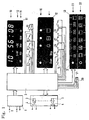
- a microprocessor 2 is supplied with current via a power supply unit 1 fed by supply current U.
- This microprocessor 2 switches a plurality of power relays 3 via their relay switch 4 to supply current to power consumers, such as power resistors for delivering thermal energy for cooking purposes, microwave generators for delivering microwave energy also for cooking purposes and / or motors for driving circulating air fans.
- the cooking process criteria for the microprocessor 2 are entered and displayed via an input / display field 5.
- This input / display field according to FIG. 2 is shown in FIG. 1 and is divided into display fields 51, 52, 53 with assigned switch symbols instead of the input elements.
- microwave power values according to display line 11 or time-related criteria (keys 7, 8) according to the display symbolism in display line 12 can be entered. If one of the keys 6, 7, 8, 9 - is actuated, a time can be entered simultaneously via a rotary switch 10, which is shown on the display line 13.
- the input keys 14, 15, 16, 17, 18 are assigned to the function input "Start”, “Stop”, “Minute minder", combined operation with time control and "thermal heating with time control”: LEDs 19 above indicate their operating state in the display area.
- a function setting rotary switch 20 is used to enter cooking process variants, which are shown in the lower display line 22 above, while the rotary switch 21 is used to set temperature values within the cooking space; the set values are shown in the upper display line 23 arranged above and the function of the oven temperature controller is signaled by an LED 24.
- the symbols in the display line 22, which are assigned to the function setting rotary switch 20, have the following meaning from left to right: “0 position”, “top and bottom heat”, “circulating air mode”, “interval grilling with circulating air mode”, “grilling” , “Automatic roasting” and “Pyrolytic self-cleaning”. Above the temperature range of up to 250 ° for normal baking and roasting operation, the grill heating output can be controlled by the temperature rotary switch 21.
- the times of day appear in display line 13.
- setting values for microwave operation can be input using the input keys 6 to 9 in accordance with the symbols arranged above and the associated time values using the rotary switch 10, whereby these time values are now shown in the display line 13 instead of the time of day.
- This readiness for input is signaled by the half-bright illumination of the display line 11.
- the display line 12 is also illuminated half-brightly until microwave setting values have been entered. After microwave values have been entered, the symbols assigned to these values are controlled for bright illumination, while the other symbols in line 11 indicate that the readiness for further inputs is ready half brightness can be controlled further. In contrast, the symbolism of the display line 12 is darkened.
- the function setting rotary switch 20 can also be set to an operating mode corresponding to the symbols of the display line 22 illuminated with half brightness. If the microwave power is already set, the "Automatic roasting" and “Pyrolytic self-cleaning” modes are not possible and the associated symbols are also darkened accordingly.
- the temperature scale in the display line 23 is originally also illuminated with half the brightness. If an operating function is selected by the function setting rotary switch 20, the associated symbols light up brightly, while the other function symbols in the display line 22 go out.
- the oven temperature is set by means of the temperature rotary switch 21, the set temperature range lights up brightly within the dimly lit temperature scale in the display line 23. Functional monitoring of the temperature controller for the oven temperature is signaled by an LED 24.
- the set thermal heating for the oven is activated at the same time as the set microwave power.
- the time control is only used for the thermal heating operation in the oven. In this case, input and processing of microwave values is not possible. This is signaled by darkening the display symbols in the display line 11.
Landscapes
- Engineering & Computer Science (AREA)
- Physics & Mathematics (AREA)
- General Physics & Mathematics (AREA)
- Automation & Control Theory (AREA)
- Chemical & Material Sciences (AREA)
- Combustion & Propulsion (AREA)
- Mechanical Engineering (AREA)
- General Engineering & Computer Science (AREA)
- Electric Ovens (AREA)
- Devices For Use In Laboratory Experiments (AREA)
- Circuit Arrangement For Electric Light Sources In General (AREA)
Abstract
Description
Die vorliegende Erfindung bezieht sich auf eine Anordnung zur Eingabe und Anzeige von Einstellwerten in Haushaltsherde zur Steuerung der Energiezuleitung an die die thermischen und/oder die hochfrequenten Heizquellen unter Verwendung einer Temperatur-Zeit-Steuerschaltung, über die der Beginn und das Ende der Energiezufuhr und das dazwischen abzuarbeitende Temperatur-Zeit-Profil für die durch Eingabe vorgegebenen Garungsprozesse sowie die dafür eingesetzten Funktionseinheiten steuerbar ist, unter Verwendung von einer Mehrzahl von Funktions-Eingabeelementen und von Anzeigeelementen in einem Eingabe-/Anzeigefeld des Elektroherdes zur Eingabe und Anzeige der erforderlichen Garungsprozeß-Kriterien.The present invention relates to an arrangement for entering and displaying setting values in domestic stoves for controlling the supply of energy to the thermal and / or high-frequency heating sources using a temperature-time control circuit, via which the start and end of the energy supply and that the temperature-time profile to be processed in between can be controlled for the cooking processes specified by input and the functional units used for this, using a plurality of function input elements and display elements in an input / display field of the electric oven for inputting and displaying the required cooking process criteria .
Es ist hinlänglich bekannt, insbesondere zur Abwicklung von Brat- und Backvorgängen eine Zeitschaltung einzusetzen, welche den Beginn und das Ende eines temperaturgeregelten Garungsprozesses schaltet, insbesondere ausgelöst durch die Entwicklung in der Halbleiter und in der Mikroprozessortechnik ist es auch bekannt geworden, Garungsprozesse automatisch zu steuern, bei welchen in unterschiedlichen vorgegebenen Garungsprozeß-Phasen unterschiedliche Heizungstemperaturwerte auftreten. Mit Hilfe dieser Anordnungen können verschiedene Garungsprozeßabläufe eingestellt werden. Die Garungsprozesse selbst laufen ab unter entsprechend dosierter Zufuhr von Wärmeenergie, ausgehend von thermischen Heizquellen, oder durch Zufuhr von Mikrowellenenergie. Beide Energiearten können bekannterweise auch gleichzeitig oder teilweise überlagert zur Beaufschlagung des Garguts herangezogen werden. Des weiteren können Garungsprozesse durch Beaufschlagung des Gargutes mit erhitzter, erwärmter oder kühler Luft vorteilhaft beeiflußt werden.It is well known to use a time switch, in particular for handling roasting and baking processes, which switches the start and end of a temperature-controlled cooking process, in particular triggered by developments in semiconductors and in microprocessor technology, it has also become known to control cooking processes automatically in which different heating temperature values occur in different predetermined cooking process phases. With the help of these arrangements, different cooking process sequences can be set. The cooking processes themselves take place with a correspondingly dosed supply of thermal energy, starting from thermal heating sources, or by supplying microwave energy. As is known, both types of energy can also be used simultaneously or partially superimposed to act on the food to be cooked. Furthermore Cooking processes can advantageously be influenced by applying heated, heated or cool air to the food.
Es ist bekannt, Eingabeorgane und Anzeigeorgane für die Eingabe und Anzeige der eingegebenen und durchgeführten Garungsprozeß-Varianten und Kombinationen vorzusehen. Die eingegebenen und/oder die ablaufenden Garungsprozeß-Informationen werden durch die Anzeigeelemente, die in diesem Fall hell gesteuert werden, angezeigt.It is known to provide input elements and display elements for the input and display of the cooking process variants and combinations that have been entered and carried out. The input and / or the running cooking process information is displayed by the display elements, which in this case are brightly controlled.
Ausgehend von diesem Stand der Technik ist es Aufgabe der vorliegenden Erfindung, eine Anordnung für die Eingabe und Anzeige von Garungsprozeß-Kriterien für Haushaltsgeräre, insbesondere Haushaltsherde bereitzustellen, die der Bedienungsperson die Möglichkeit eröffnet, die mögliche Eingabevielfalt der jeweiligen Eingabekriterien zu eröffnen.Starting from this prior art, it is an object of the present invention to provide an arrangement for the input and display of cooking process criteria for household appliances, in particular domestic stoves, which opens up the possibility for the operator to open up the possible input variety of the respective input criteria.
Eine Anordnung, bei für die Durchführung von Mikrowellen-Garungsprozessen und thermischen Garungsprozessen sowie für zeitliche Abläufe eigene Eingaben- und Anzeigelemente angeordnet sind, ist zur Lösung der gestellten Aufgabe vorteilhaft dadurch gekennzeichnet, daß eingabebereiten Funktionseingabeelementen zugeordnete Leuchtanzeigeelemente durch die Steuerschaltung mit gegenüber der Ansteuerleistung von Leuchtanzeigelementen, welche eingegeben und/oder ablaufende Funktionswerte anzeigen, veränderter Ansteuerleistung angesteuert werden, so daß die den eingabebereiten Funktionseingabeelementen zugeordneten Leuchtanzeigeelemente mit gegenüber den Leuchtelementen für eingegebene und/oder ablaufende Funktionswerte verändert leuchten. Durch entsprechende Wahl der lichterzeugenden Elemente kann beispielsweise eine Farbverschiebung bzw. Farbänderung in diesem Zusammenhang realisiert werden. Nach einer bevorzugten Ausgestaltung ist die erfindungsgemäße Anordnung jedoch dahingehend weitergebildet, daß die den eingabebereiten Funktionseingabeelementen zugeordneten Leuchtanzeigeelemente mit verringerter Leistung durch die Steuerschaltung angesteuert werden. Es erweist sich in diesem Zusammenhang als brauchbare Maßnahme, wenn diese besagten, den eingabebereiten Funktionseingabetasten zugeordneten Leuchtanzeigeelemente derart angesteuert werden, daß ihre Leuchtstärke auf annähernd den halben Wert der Leuchtstärke der Anzeigeelemente, die eingegebene oder ablaufende Funktionswerte anzeigen, reduziert wird.An arrangement in which separate input and display elements are arranged for the implementation of microwave cooking processes and thermal cooking processes as well as for temporal sequences is advantageously characterized in that the task at hand is characterized in that function display elements that are ready for input are assigned illuminated display elements assigned to the control circuit by means of the control circuit with respect to the actuating power of illuminated display elements , which are input and / or display running function values, are controlled to change the control power, so that the illuminated display elements assigned to the input-ready function input elements light up differently from the lighting elements for input and / or running function values. By appropriate selection of the light-generating elements, for example, a color shift or color change can be realized in this context. According to a preferred embodiment, however, the arrangement according to the invention is further developed in such a way that the illuminated display elements assigned to the input-ready functional input elements are controlled with reduced power by the control circuit. It proves to be a useful measure in this context if these light indicator elements assigned to the input-ready function input keys are controlled in such a way that their luminosity is reduced to approximately half the luminance of the display elements which indicate input or expired function values.
Bevorzugterweise sind die Leuchtanzeigeelemente für die Anzeige von -numerischer Zeichen und von Symbolen Leuchtsegmentanzeigen und für ledigliche Anzeige von Schaltzuständen der Eingabeorgane-Leuchtdioden.The light-emitting display elements are preferably light-segment displays for the display of -numerical characters and symbols and only for the display of switching states of the input elements-light emitting diodes.
Mit Hilfe der erfindungsgemäß getroffenen Maßnahmen ist die Anordnung zur Eingabe und Anzeige von Einstellwerten in Haushaltsherden im besonderem Maße ertüchtigt, Bedienungspersonen nicht nur die eingegebenen und durchgeführten Eingabekriterien anzuzeigen und ggf. einen Hinweis auf den nächsten erforderlichen Schritt zu geben, sondern auch die jeweils gegebene Vielfalt der noch gegebenen Eingabemöglichkeiten zu signalisieren.With the help of the measures taken according to the invention, the arrangement for inputting and displaying setting values in domestic stoves is particularly efficient in not only displaying to operators the inputted and carried out input criteria and, if necessary, giving an indication of the next required step, but also the given variety to signal the input options still available.
Anhand eines durch die Zeichnung sinnbildlich veranschaulichten Ausführungsbeispiels wird eine nach den Merkmalen der Erfindung ausgestattete Anordnung, insbesondere im Hinblick auf deren Benutzeroberfläche näher beschrieben.On the basis of an exemplary embodiment illustrated by the drawing, an arrangement equipped according to the features of the invention, in particular with regard to its user interface, is described in more detail.
Es zeigen:
- Fig. 1 ein Eingabe-Anzeigefeld für einen Haushaltsherd, in Verbindung mit einem vereinfachten Blockschaltbild und
- Fig. 2 die Eingabe-/Anzeigefelder, wie sie in der Bedienfront eines Haushaltherdes neben den Bedienelementen von Kochfeldern angeordnet sind.
- Fig. 1 is an input display field for a household stove, in connection with a simplified block diagram and
- Fig. 2, the input / display fields, as they are arranged in the front of a household stove next to the controls of hobs.
Über ein von Versorgungsstrom U gespeistes Netzteil 1 wird ein Mikroprozessor 2 mit Strom versorgt. Dieser Mikroprozessor 2 schaltet über eine Mehrzahl von Leistungsrelais 3 über deren Relaisschalter 4 Versorgungsstrom an Leistungsverbraucher, wie Leistungswiderstände zur Abgabe von thermischer Energie zu Garungszwecken, Mikrowellen-Generatoren zur Abgabe von Mikrowellenenergie ebenfalls zu Garungszwecken und/oder Motoren zum Antrieb von Umluftgebläsen.A microprocessor 2 is supplied with current via a
Über ein Eingabe-/Anzeigefeld 5 erfolgt die Eingabe und Anzeige der Garungsprozeß-Kriterien für den Mikroprozessor 2. Dieses Eingabe-/Anzeigefeld nach Figur 2 ist in Figur 1 aufgeteilt dargestellt in Anzeigefelder 51, 52, 53 mit zugeordneten Schaltersymbolen anstelle der Eingabeorgane.The cooking process criteria for the microprocessor 2 are entered and displayed via an input / display field 5. This input / display field according to FIG. 2 is shown in FIG. 1 and is divided into
Über Tasten 6, 7, 8, 9 sind wahlweise je nach Vorgabe Mikrowellen-Leistungswerte gemäß Anzeigezeile 11 oder zeitbedingende Kriterien (Tasten 7, 8) entsprechend der Anzeigesymbolik in der Anzeigezeile 12 eingebbar. Wenn eine der Tasten 6, 7, 8, 9 - betätigt ist, kann gleichzeitig über einen Drehschalter 10 eine Zeiteingabe erfolgen, die in der Anzeigezeile 13 angezeigt wird. Die Eingabetasten 14, 15, 16, 17, 18 sind der Funktionseingabe "Start", "Stop", "Kurzzeitwecker", zugeordnet, Kombinationsbetrieb mit Zeitsteuerung und "thermischer Heizung mit Zeitsteuerung": im Anzeigebereich darüber signalisieren Leuchtdioden 19 deren Betriebszustand. Ein Funktionseinstell-Drehschalter 20 dient zur Eingabe von Garungsprozeßvarianten, die in der daruberliegenden unteren Anzeigezeile 22 dargestellt sind, während der Drehschalter 21 zur Einstellung von Temperaturwerten innerhalb des Garraums dient; die eingestellten Werte werden in der darüber angeordneten oberen Anzeigezeile 23 angezeigt und die Funktion des Backofentemperaturreglers durch eine Leuchtdiode 24 signalisiert.Using
Die Symbole in der Anzeigezeile 22, die dem Funktionseinstell-Drehschalter 20 zugeordnet sind, haben von links nach rechts folgende Bedeutung: "0-Stellung", "Ober- und Unterhitze", "umluftbetrieb", "Intervallgrillen mit Umluftbetrieb", "Grillen", "Bratautomatik" und "Pyrolythische Selbstreinigung". Oberhalb des bis 250° reichenden Temperaturbereichs für den normalen Back- und Bratbetrieb kann durch den Temperatur-Drehschalter 21 die Grill-Heizleistung angesteuert werden.The symbols in the
In der Anzeigezeile 13 erscheint, solange keine sonstigen eingegebenen Zeitwerte zur Anzeige gebracht werden sollen, die Tageszeiten. Mit Ausnahme der Einstellung des Funktionseinstell-Drehschalters 20 auf die Betriebsarten "Bratautomatik" und "Pyrolythische Selbstreinigung"können Einstellwerte für den Mikrowellenbetrieb über die Eingabetasten 6 bis 9 entsprechend der darüber angeordneten Symbolik und die dazu gehörigen Zeitwerte mit Hilfe des Drehschalters 10 eingegeben werden, wobei diese Zeitwerte nunmehr anstelle der Tageszeit in der Anzeigezeile 13 angezeigt werden. Diese Eingabebereitschaft wird signalisiert durch die halbhelle Ausleuchtung der Anzeigezeile 11. Bis zur Eingabe von Mikrowellen-Einstellwerten ist auch die Anzeigezeile 12 halbhell ausgeleuchtet. Nach der Eingabe von Mikrowellenwerten wird die diesen Werten zugeordnete Symbolik auf helle Ausleuchtung gesteuert, während die übrigen Symbole der Zeile 1 1 zur Anzeige der Bereitschaft für weitere Eingaben auf halbe Helligkeit weiter angesteuert werden. Dagegen wird die Symbolik der Anzeigezeile 12 dunkel gesteuert.As long as no other entered time values are to be displayed, the times of day appear in
Gesondert oder parallel dazu kann der Funktionseinstell-Drehschalter 20 ebenfalls auf eine Betriebsart entsprechend der mit halber Helligkeit ausgeleuchteten Symboliken der Anzeigezeile 22 eingestellt werden. Bei bereits eingestellter Mikrowellenleistung sind die Betriebsarten "Bratautomatik" und "Pyrolythische Selbstreinigung" nicht möglich und entsprechend sind die zugeordneten Symbole auch dunkel gesteuert. Die Temperaturskala in der Anzeigezeile 23 ist ursprünglich ebenfalls mit halber Helligkeit ausgeleuchtet. Wird durch den Funktionseinstell-Drehschalter 20 eine Betriebsfunktion ausgewählt, so leuchtet die zugeordnete Symbolik hell auf, während die übrigen Funktionssymbole in der Anzeigezeile 22 erlöschen. Bei einer Einstellung der Backofentemperatur durch den Temperatur-Drehschalter 21 leuchtet innerhalb der schwach leuchtenden Temperaturskala in der Anzeigezeile 23 der eingestellte Temperaturbereich hell auf. Die Funktionsüberwachung des Temperaturreglers für die Backofentemperatur signalisiert eine Leuchtdiode 24.Separately or in parallel, the function setting
Bei Auswahl der Betriebsarten "Bratautomatik" und "Pyrolythische Selbstreinigung" erlöschen sämtliche weiteren Anzeigesymbole, da dann weitere Eingaben ohnehin nicht möglich sind. Eine Ausnahme bildet die Symbolik für die Starttaste 14, da diese Taste zum Start dieser Betriebsarten betätigt werden muß. Ebenso dient diese Taste zum Start des Garbetriebs mit Mikrowellenleistung.When the "Automatic roasting" and "Pyrolytic self-cleaning" modes are selected, all other display symbols go out, since then further entries are not possible anyway. The symbols for the
Wird die Taste 17 betätigt, so wird die eingestellte thermische Heizung für den Backofen zeitlich parallel mit der eingestellten Mikrowellenleistung angesteuert. Bei betätigter Eingabetaste 18 wird die Zeitsteuerung lediglich für den thermischen Heizbetrieb im Backofen benutzt. In diesem Fall ist eine Eingabe- und Abarbeitung von Mikrowellenwerten nicht möglich. Dies wird durch Dunkelsteuerung der Anzeigesymbole in der Anzeigezeile 11 signalisiert.If the
Claims (4)
Applications Claiming Priority (2)
| Application Number | Priority Date | Filing Date | Title |
|---|---|---|---|
| DE3803923A DE3803923A1 (en) | 1988-02-09 | 1988-02-09 | ARRANGEMENT FOR ENTERING AND DISPLAYING SETTINGS, IN PARTICULAR IN HOUSEHOLD COOKERS |
| DE3803923 | 1988-02-09 |
Publications (4)
| Publication Number | Publication Date |
|---|---|
| EP0328025A2 true EP0328025A2 (en) | 1989-08-16 |
| EP0328025A3 EP0328025A3 (en) | 1989-11-02 |
| EP0328025B1 EP0328025B1 (en) | 1991-12-11 |
| EP0328025B2 EP0328025B2 (en) | 1995-08-23 |
Family
ID=6346996
Family Applications (1)
| Application Number | Title | Priority Date | Filing Date |
|---|---|---|---|
| EP89102021A Expired - Lifetime EP0328025B2 (en) | 1988-02-09 | 1989-02-06 | Input and display arrangement of control valves, specially for cooking appliances |
Country Status (3)
| Country | Link |
|---|---|
| EP (1) | EP0328025B2 (en) |
| DE (2) | DE3803923A1 (en) |
| ES (1) | ES2027047T5 (en) |
Cited By (4)
| Publication number | Priority date | Publication date | Assignee | Title |
|---|---|---|---|---|
| FR2688872A1 (en) * | 1992-02-24 | 1993-09-24 | Toshiba Kk | HEATING APPARATUS COMPRISING MEANS FOR SELECTING COOKING MENUS. |
| WO2003014624A1 (en) * | 2001-08-08 | 2003-02-20 | BSH Bosch und Siemens Hausgeräte GmbH | Cooking device |
| EP1479977A3 (en) * | 2003-03-26 | 2008-08-13 | BSH Bosch und Siemens Hausgeräte GmbH | Cooking oven device |
| DE102012218316A1 (en) * | 2012-10-08 | 2014-04-10 | BSH Bosch und Siemens Hausgeräte GmbH | Operating device for a household appliance, household appliance with such an operating device and method of an operating device |
Families Citing this family (6)
| Publication number | Priority date | Publication date | Assignee | Title |
|---|---|---|---|---|
| GB2267554B (en) * | 1992-06-01 | 1995-08-02 | Matsushita Electric Industrial Co Ltd | Heating apparatus |
| DE4415532C2 (en) * | 1994-05-03 | 1996-09-26 | Reiner Dipl Ing Kuehn | Process for heating a good |
| DE19606115A1 (en) * | 1995-02-20 | 1996-08-22 | Miele & Cie | Control shutter for combined electric and microwave oven |
| DE10138062B4 (en) * | 2001-08-03 | 2011-09-22 | BSH Bosch und Siemens Hausgeräte GmbH | hob |
| ES2222804B1 (en) * | 2003-06-13 | 2005-10-01 | Bsh Electrodomesticos España, S.A. | PROCEDURE FOR HEATING A CONTAINER SENSITIVE TO THE TEMPERATURE AND CORRESPONDING WARMING DEVICE. |
| DE102016223848A1 (en) * | 2016-11-30 | 2018-05-30 | E.G.O. Elektro-Gerätebau GmbH | Hob and method of operating such a hob |
Family Cites Families (4)
| Publication number | Priority date | Publication date | Assignee | Title |
|---|---|---|---|---|
| JPS592982B2 (en) * | 1978-05-29 | 1984-01-21 | 日本ビクター株式会社 | music selection device |
| DE3010715A1 (en) * | 1980-03-20 | 1981-09-24 | Bauknecht Gmbh G | Operating control panel esp. for domestic cooker - has ten unit pushbutton keyboard for time input, 24 hour time display and LEDs for indicating various functions |
| FR2561358B1 (en) * | 1984-03-13 | 1989-05-05 | Europ Equip Menager | INTERACTIVE CONTROLLED COOKING APPARATUS |
| US4899140A (en) * | 1986-09-13 | 1990-02-06 | Minolta Camera Kabushiki Kaisha | Display device for copying machines and the like |
-
1988
- 1988-02-09 DE DE3803923A patent/DE3803923A1/en not_active Withdrawn
-
1989
- 1989-02-06 EP EP89102021A patent/EP0328025B2/en not_active Expired - Lifetime
- 1989-02-06 ES ES89102021T patent/ES2027047T5/en not_active Expired - Lifetime
- 1989-02-06 DE DE8989102021T patent/DE58900540D1/en not_active Expired - Lifetime
Cited By (6)
| Publication number | Priority date | Publication date | Assignee | Title |
|---|---|---|---|---|
| FR2688872A1 (en) * | 1992-02-24 | 1993-09-24 | Toshiba Kk | HEATING APPARATUS COMPRISING MEANS FOR SELECTING COOKING MENUS. |
| WO2003014624A1 (en) * | 2001-08-08 | 2003-02-20 | BSH Bosch und Siemens Hausgeräte GmbH | Cooking device |
| US7247821B2 (en) | 2001-08-08 | 2007-07-24 | Bsh Bosch Und Siemens Hausgeraete Gmbh | Cooking device with luminous display |
| EP1479977A3 (en) * | 2003-03-26 | 2008-08-13 | BSH Bosch und Siemens Hausgeräte GmbH | Cooking oven device |
| DE102012218316A1 (en) * | 2012-10-08 | 2014-04-10 | BSH Bosch und Siemens Hausgeräte GmbH | Operating device for a household appliance, household appliance with such an operating device and method of an operating device |
| WO2014056751A1 (en) * | 2012-10-08 | 2014-04-17 | BSH Bosch und Siemens Hausgeräte GmbH | Operating device for a domestic appliance, domestic appliance with such an operating device, and operating device method |
Also Published As
| Publication number | Publication date |
|---|---|
| EP0328025B2 (en) | 1995-08-23 |
| EP0328025B1 (en) | 1991-12-11 |
| ES2027047T3 (en) | 1992-05-16 |
| DE58900540D1 (en) | 1992-01-23 |
| DE3803923A1 (en) | 1989-08-17 |
| EP0328025A3 (en) | 1989-11-02 |
| ES2027047T5 (en) | 1995-11-01 |
Similar Documents
| Publication | Publication Date | Title |
|---|---|---|
| JP2525736B2 (en) | Control device for electric consumer of electric oven | |
| DE3519230C2 (en) | ||
| DE19832757C2 (en) | Method for controlling a cooking appliance, a washing machine or a dishwasher and a cooking appliance, washing machine or dishwasher with a graphic display device | |
| EP0328025B1 (en) | Input and display arrangement of control valves, specially for cooking appliances | |
| EP0596263B1 (en) | Cooking oven | |
| US7247821B2 (en) | Cooking device with luminous display | |
| EP0213442B1 (en) | Arrangement for controlling ovens employing micro-waves and/or heat energy | |
| DE10107206C5 (en) | Touch-sensitive control panel for cooking zones | |
| DE102016214111A1 (en) | household appliance | |
| EP0383107A2 (en) | Arrangement for controlling the heating time intervals and the heating capacities of cookers | |
| DE3104662A1 (en) | Device for displaying presettable operating states | |
| DE4407741A1 (en) | Sensor with switch for connecting and disconnecting electrical load e.g. heater in cooker | |
| EP0025476B1 (en) | Switch position indicating device for an electric range | |
| AT394262B (en) | DEVICE FOR SETTING AND MONITORING A HEATING SYSTEM | |
| DE8913602U1 (en) | Electric cooker with a switch panel for operating switches and control lamps for the cooking zones and/or the oven | |
| DE19802932C2 (en) | Method for displaying an operating state of a hotplate | |
| DE3501150C2 (en) | ||
| DE19861219C5 (en) | Domestic electric appliance control | |
| CN216017221U (en) | Color difference lamp | |
| JPH07332684A (en) | Display operation device of cooking device | |
| EP3001108B1 (en) | Electronic household appliance | |
| EP4710045A1 (en) | Domestic appliance system, and method for operating a domestic appliance system | |
| EP1768460A1 (en) | Electrical heating plate with lighting device | |
| JPH01193524A (en) | electric range | |
| KR20190109290A (en) | Method for operator control of an electric cooking appliance, and electric cooking appliance |
Legal Events
| Date | Code | Title | Description |
|---|---|---|---|
| PUAI | Public reference made under article 153(3) epc to a published international application that has entered the european phase |
Free format text: ORIGINAL CODE: 0009012 |
|
| AK | Designated contracting states |
Kind code of ref document: A2 Designated state(s): CH DE ES FR GB IT LI NL SE |
|
| PUAL | Search report despatched |
Free format text: ORIGINAL CODE: 0009013 |
|
| AK | Designated contracting states |
Kind code of ref document: A3 Designated state(s): CH DE ES FR GB IT LI NL SE |
|
| 17P | Request for examination filed |
Effective date: 19891117 |
|
| 17Q | First examination report despatched |
Effective date: 19900507 |
|
| GRAA | (expected) grant |
Free format text: ORIGINAL CODE: 0009210 |
|
| AK | Designated contracting states |
Kind code of ref document: B1 Designated state(s): CH DE ES FR GB IT LI NL SE |
|
| REF | Corresponds to: |
Ref document number: 58900540 Country of ref document: DE Date of ref document: 19920123 |
|
| RAP2 | Party data changed (patent owner data changed or rights of a patent transferred) |
Owner name: BOSCH-SIEMENS HAUSGERAETE GMBH |
|
| ET | Fr: translation filed | ||
| ITF | It: translation for a ep patent filed | ||
| GBT | Gb: translation of ep patent filed (gb section 77(6)(a)/1977) | ||
| PLBI | Opposition filed |
Free format text: ORIGINAL CODE: 0009260 |
|
| 26 | Opposition filed |
Opponent name: MIELE & CIE. GMBH & CO Effective date: 19920908 |
|
| NLR1 | Nl: opposition has been filed with the epo |
Opponent name: MIELE & CIE GMBH & CO. |
|
| RAP4 | Party data changed (patent owner data changed or rights of a patent transferred) |
Owner name: BOSCH-SIEMENS HAUSGERAETE GMBH |
|
| EAL | Se: european patent in force in sweden |
Ref document number: 89102021.6 |
|
| PUAH | Patent maintained in amended form |
Free format text: ORIGINAL CODE: 0009272 |
|
| STAA | Information on the status of an ep patent application or granted ep patent |
Free format text: STATUS: PATENT MAINTAINED AS AMENDED |
|
| 27A | Patent maintained in amended form |
Effective date: 19950823 |
|
| AK | Designated contracting states |
Kind code of ref document: B2 Designated state(s): CH DE ES FR GB IT LI NL SE |
|
| REG | Reference to a national code |
Ref country code: CH Ref legal event code: AEN |
|
| NLR2 | Nl: decision of opposition | ||
| GBTA | Gb: translation of amended ep patent filed (gb section 77(6)(b)/1977) |
Effective date: 19950913 |
|
| REG | Reference to a national code |
Ref country code: ES Ref legal event code: DC2A Kind code of ref document: T5 Effective date: 19951101 |
|
| ITF | It: translation for a ep patent filed | ||
| ET3 | Fr: translation filed ** decision concerning opposition | ||
| NLR3 | Nl: receipt of modified translations in the netherlands language after an opposition procedure | ||
| PGFP | Annual fee paid to national office [announced via postgrant information from national office to epo] |
Ref country code: SE Payment date: 19970110 Year of fee payment: 9 |
|
| PGFP | Annual fee paid to national office [announced via postgrant information from national office to epo] |
Ref country code: NL Payment date: 19970228 Year of fee payment: 9 |
|
| PGFP | Annual fee paid to national office [announced via postgrant information from national office to epo] |
Ref country code: CH Payment date: 19970324 Year of fee payment: 9 |
|
| PG25 | Lapsed in a contracting state [announced via postgrant information from national office to epo] |
Ref country code: SE Free format text: LAPSE BECAUSE OF NON-PAYMENT OF DUE FEES Effective date: 19980207 |
|
| PGFP | Annual fee paid to national office [announced via postgrant information from national office to epo] |
Ref country code: ES Payment date: 19980227 Year of fee payment: 10 |
|
| PG25 | Lapsed in a contracting state [announced via postgrant information from national office to epo] |
Ref country code: LI Free format text: LAPSE BECAUSE OF NON-PAYMENT OF DUE FEES Effective date: 19980228 Ref country code: CH Free format text: LAPSE BECAUSE OF NON-PAYMENT OF DUE FEES Effective date: 19980228 |
|
| PG25 | Lapsed in a contracting state [announced via postgrant information from national office to epo] |
Ref country code: NL Free format text: LAPSE BECAUSE OF NON-PAYMENT OF DUE FEES Effective date: 19980901 |
|
| REG | Reference to a national code |
Ref country code: CH Ref legal event code: PL |
|
| EUG | Se: european patent has lapsed |
Ref document number: 89102021.6 |
|
| NLV4 | Nl: lapsed or anulled due to non-payment of the annual fee |
Effective date: 19980901 |
|
| PG25 | Lapsed in a contracting state [announced via postgrant information from national office to epo] |
Ref country code: ES Free format text: LAPSE BECAUSE OF NON-PAYMENT OF DUE FEES Effective date: 20000207 |
|
| REG | Reference to a national code |
Ref country code: ES Ref legal event code: FD2A Effective date: 20010910 |
|
| REG | Reference to a national code |
Ref country code: GB Ref legal event code: IF02 |
|
| PGFP | Annual fee paid to national office [announced via postgrant information from national office to epo] |
Ref country code: FR Payment date: 20020221 Year of fee payment: 14 |
|
| PGFP | Annual fee paid to national office [announced via postgrant information from national office to epo] |
Ref country code: GB Payment date: 20030127 Year of fee payment: 15 |
|
| PGFP | Annual fee paid to national office [announced via postgrant information from national office to epo] |
Ref country code: DE Payment date: 20030317 Year of fee payment: 15 |
|
| PG25 | Lapsed in a contracting state [announced via postgrant information from national office to epo] |
Ref country code: FR Free format text: LAPSE BECAUSE OF NON-PAYMENT OF DUE FEES Effective date: 20031031 |
|
| REG | Reference to a national code |
Ref country code: FR Ref legal event code: ST |
|
| PG25 | Lapsed in a contracting state [announced via postgrant information from national office to epo] |
Ref country code: GB Free format text: LAPSE BECAUSE OF NON-PAYMENT OF DUE FEES Effective date: 20040206 |
|
| PG25 | Lapsed in a contracting state [announced via postgrant information from national office to epo] |
Ref country code: DE Free format text: LAPSE BECAUSE OF NON-PAYMENT OF DUE FEES Effective date: 20040901 |
|
| GBPC | Gb: european patent ceased through non-payment of renewal fee |
Effective date: 20040206 |
|
| PG25 | Lapsed in a contracting state [announced via postgrant information from national office to epo] |
Ref country code: IT Free format text: LAPSE BECAUSE OF NON-PAYMENT OF DUE FEES;WARNING: LAPSES OF ITALIAN PATENTS WITH EFFECTIVE DATE BEFORE 2007 MAY HAVE OCCURRED AT ANY TIME BEFORE 2007. THE CORRECT EFFECTIVE DATE MAY BE DIFFERENT FROM THE ONE RECORDED. Effective date: 20050206 |