EP0327955A2 - Radialer Luftreifen - Google Patents
Radialer Luftreifen Download PDFInfo
- Publication number
- EP0327955A2 EP0327955A2 EP89101776A EP89101776A EP0327955A2 EP 0327955 A2 EP0327955 A2 EP 0327955A2 EP 89101776 A EP89101776 A EP 89101776A EP 89101776 A EP89101776 A EP 89101776A EP 0327955 A2 EP0327955 A2 EP 0327955A2
- Authority
- EP
- European Patent Office
- Prior art keywords
- belt layer
- tire
- folded
- layers
- belt
- Prior art date
- Legal status (The legal status is an assumption and is not a legal conclusion. Google has not performed a legal analysis and makes no representation as to the accuracy of the status listed.)
- Withdrawn
Links
Images


Classifications
-
- B—PERFORMING OPERATIONS; TRANSPORTING
- B60—VEHICLES IN GENERAL
- B60K—ARRANGEMENT OR MOUNTING OF PROPULSION UNITS OR OF TRANSMISSIONS IN VEHICLES; ARRANGEMENT OR MOUNTING OF PLURAL DIVERSE PRIME-MOVERS IN VEHICLES; AUXILIARY DRIVES FOR VEHICLES; INSTRUMENTATION OR DASHBOARDS FOR VEHICLES; ARRANGEMENTS IN CONNECTION WITH COOLING, AIR INTAKE, GAS EXHAUST OR FUEL SUPPLY OF PROPULSION UNITS IN VEHICLES
- B60K17/00—Arrangement or mounting of transmissions in vehicles
-
- B—PERFORMING OPERATIONS; TRANSPORTING
- B60—VEHICLES IN GENERAL
- B60C—VEHICLE TYRES; TYRE INFLATION; TYRE CHANGING; CONNECTING VALVES TO INFLATABLE ELASTIC BODIES IN GENERAL; DEVICES OR ARRANGEMENTS RELATED TO TYRES
- B60C9/00—Reinforcements or ply arrangement of pneumatic tyres
- B60C9/18—Structure or arrangement of belts or breakers, crown-reinforcing or cushioning layers
- B60C9/26—Folded plies
-
- B—PERFORMING OPERATIONS; TRANSPORTING
- B60—VEHICLES IN GENERAL
- B60C—VEHICLE TYRES; TYRE INFLATION; TYRE CHANGING; CONNECTING VALVES TO INFLATABLE ELASTIC BODIES IN GENERAL; DEVICES OR ARRANGEMENTS RELATED TO TYRES
- B60C11/00—Tyre tread bands; Tread patterns; Anti-skid inserts
Definitions
- a radial tire basically comprises a carcass layer 14 consisting of cords each substantially perpendicular to the circumferential direction of the tire and having both end portions each folded back about a bead wire 13 from the inside of the tire towards the outside thereof, a belt layer 15 comprising two layers, i.e., an upper belt layer 15u and a lower belt layer 15d, each provided between a tread 11 provided at the center portion of the tire and the carcass layer 14, and a sidewall portion 12 provided on the side portion of the tire, as shown in Fig. 2.
- the above-described conventional radial tire is liable to bring about a lowering in the high speed durability because both the end portions of the belt layer will rise during high-speed travelling.
- Some tires have a belt covering material provided on the outer periphery on each shoulder side of the belt layer for the purpose of preventing the rise of the end portions of the belt layer.
- the provision of the covering material has brought about a drawback that not only the productivity of the tire is lowered but also an uniformity of the tire is lowered or spot abrasion is occurred in order to change in the rigidity in the circumferential direction of the tire by the splice portion formed in the covering material.
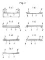
- FIGs. 3(a) to (g) are schematic cross-sectional views of examples of a belt layer having the above-described folded belt structure.
- edges 4 of the belt layer are exposed on the shoulder portion. This exposure causes the edge portions 4 of the belt layer to be separated because deformation (strain) of the shoulder portion increases during travelling, which lowers the durability of the tire.
- An object of the present invention is to provide a pneumatic radial tire improved in not only the high speed durability and heavy-load durability, particularly the former, but also the driving stability over the tire having a conventional folded belt structure.
- the radial tire of the present invention is characterized by having a belt structure wherein both end portions of at least two layers are folded back towards the inside of the tire and the folded portions are integrally overlapped on top of the other.
- the belt layer comprising at least two layers may have a structure comprising two layers 1 and 1′ shown in Figs. 1(a) and (b) or a structure comprising three layers 1, 1′ and 1 ⁇ shown in Figs. 1(c) and (d).
- both end portions of each of two layers 1 and 1′ are folded back towards the inside of the tire to form a folded belt structure
- both end portions of each of at least two layers 1 and 1′ are folded back towards the inside of the tire to form a folded belt structure.
- folded portions 3, 3′ not only enhances the effect of reinforcing the belt layer, particularly the effect of reinforcing the shoulder side of the belt layer during high-speed travelling but also increases the in-plane flexural rigidity of the entire belt layer, which makes it possible to increase the cornering power of the tire.
- the folded portion widths l1 and l2 of the belt layer in the folded portions are each 1/8 to 1/2 exclusive of the total width L of the belt layer.
- the edges of the folded portions are overlapped on top of the other at the center portion of the belt layer. This excessively increases the rigidity of the center portion of the belt layer, so that the driving stability is lowered. Further, since this causes the edges of the folded portions to be provided around the center of the tire, the interlaminar shear stress of the belt layer is decreased.
- the widths l1 and l2 of the folded portions of the belt layer having a two-layer structure may be the same or different. However, as shown in Fig. 1(a), when the width l2 of the folded portion of the lower belt layer 1 is larger than the width l1 of the folded portion of the upper belt layer 1′, adhesion between these two belt layers is improved, which effectively prevents the occurrence of the separation.
- the end portion of the third belt layer 1 ⁇ need not necessarily be folded back. However, in order to prevent the separation between the laminated belt layers, it is preferred to enclose each end of the third belt layer 1 ⁇ in the folded portion of the two belt layers 1 and 1′ [Fig. 1(c)] or sandwich the belt layer 1 ⁇ between the belt layers 1 and 1′ [Fig. 1(d)].
- cords constituting a belt layer comprising at least two layers having folded end portions are disposed on the bias to each other at an angle of 15° to 30° relative to the circumferential direction of the tire to form a bias folded structure.
- the separation between belt layers is suppressed through enhancement in the reinforcement of the shoulder side of the belt layer by folding back both end portions of a belt layer comprising at least two layers towards the inside of the tire and integrally overlapping the folded portions on top of the other.
- the tire of the present invention brings about no lowering in the productivity as opposed to the conventional tire having a belt covering material provided on the outer periphery on the shoulder side of the belt layer and has improved uniformity and resistance to uneven abrasion.
- An aromatic polyamide fiber cord of 1500 D/2 was used as a cord material for a belt layer to prepare a belt layer having a cord end count of 52 per 50 mm and a cord angle of 20° relative to the circumferential direction of the tire.
- a comparative tire having a belt structure shown in Fig. 3(a) was prepared by making use of a belt layer comprising the same cord material and the tire size as that used in the tire of the present invention.
- the folded portion width l of the belt layer was L/4.
- An indoor drum tester having a drum diameter of 1707 mm was used for this purpose.
- a tire having an internal pressure of 3.0 kgf/cm2 and a load of 385 kg (JIS design normal load) was mounted on this tester, and the speed of rotation of the drum was increased from an initial speed of 170 km/hr by 10 km/hr for every 10 min until the tire was broken.
- the speed of rotation required for breaking the tire was used as the measure of the high speed durability and expressed in the form of an index by taking the speed of rotation required for breaking the tire as 100.
- a tire having an internal pressure of 2.5 kgf/cm2 (JIS max. pressure) and a load of 385 kg (JIS design normal load) was mounted on the same indoor drum tester as that used for the evaluation of the above-described high speed durability and travelled at a speed of 81 km/hr.
- the load was increased by a value corresponding to 15% of the initial load for every 4 hr until the tire was broken, and the load required for breaking the tire was used as the measure of the load durability.
- the load durability was expressed in the form of an index by taking the load required for breaking the tire as 100.
- a plate cornering tester was used for this purpose. Specifically, the driving stability was evaluated by making use of the indoor cornering tester under the following conditions and expressed in terms of an index by taking the cornering power (CP) of the comparative tire as 100: Internal pressure: JIS design normal pressure of 1.9 kgf/cm2 load: JIS design normal load of 385 kg speed: 10 km/hr tire of the present invention comparative tire high speed durability 130 100 load durability 105 100 driving stability 120 100
- the tire of the present invention is superior to the comparative tire in all of the high speed durability, load durability, and driving stability.
Landscapes
- Engineering & Computer Science (AREA)
- Mechanical Engineering (AREA)
- Chemical & Material Sciences (AREA)
- Combustion & Propulsion (AREA)
- Transportation (AREA)
- Tires In General (AREA)
Applications Claiming Priority (2)
| Application Number | Priority Date | Filing Date | Title |
|---|---|---|---|
| JP63025769A JPH01202503A (ja) | 1988-02-08 | 1988-02-08 | 空気入りラジアルタイヤ |
| JP25769/88 | 1988-02-08 |
Publications (2)
| Publication Number | Publication Date |
|---|---|
| EP0327955A2 true EP0327955A2 (de) | 1989-08-16 |
| EP0327955A3 EP0327955A3 (de) | 1989-10-18 |
Family
ID=12175051
Family Applications (1)
| Application Number | Title | Priority Date | Filing Date |
|---|---|---|---|
| EP89101776A Withdrawn EP0327955A3 (de) | 1988-02-08 | 1989-02-02 | Radialer Luftreifen |
Country Status (3)
| Country | Link |
|---|---|
| EP (1) | EP0327955A3 (de) |
| JP (1) | JPH01202503A (de) |
| KR (1) | KR890012820A (de) |
Cited By (4)
| Publication number | Priority date | Publication date | Assignee | Title |
|---|---|---|---|---|
| US5355922A (en) * | 1991-04-11 | 1994-10-18 | The Yokohama Rubber Co., Ltd. | Pneumatic radial tire for passenger caps |
| WO1999041092A1 (en) * | 1998-02-16 | 1999-08-19 | The Goodyear Tire & Rubber Company | Tire with buried overlay |
| EP0965463A3 (de) * | 1998-06-19 | 2001-08-16 | The Goodyear Tire & Rubber Company | Gürtelverstärkungsstruktur für einen Luftreifen |
| US6546983B1 (en) | 1998-02-16 | 2003-04-15 | The Goodyear Tire & Rubber Company | Tire with buried overlay |
Family Cites Families (5)
| Publication number | Priority date | Publication date | Assignee | Title |
|---|---|---|---|---|
| BE550080A (de) * | 1956-03-08 | |||
| FR1228241A (fr) * | 1959-03-10 | 1960-08-29 | Mft Fr Pneumatiques Michelin | Perfectionnements apportés aux enveloppes de pneumatiques munies d'une armature de sommet |
| FR2236676B1 (de) * | 1973-07-11 | 1976-09-17 | Kleber Colombes | |
| FR223770A (de) * | 1973-07-20 | |||
| FR2376763A1 (fr) * | 1977-01-05 | 1978-08-04 | Kleber Colombes | Pneumatique pour tracteurs agricoles ou engins similaires |
-
1988
- 1988-02-08 JP JP63025769A patent/JPH01202503A/ja active Pending
-
1989
- 1989-02-02 EP EP89101776A patent/EP0327955A3/de not_active Withdrawn
- 1989-02-03 KR KR1019890001261A patent/KR890012820A/ko not_active Ceased
Cited By (4)
| Publication number | Priority date | Publication date | Assignee | Title |
|---|---|---|---|---|
| US5355922A (en) * | 1991-04-11 | 1994-10-18 | The Yokohama Rubber Co., Ltd. | Pneumatic radial tire for passenger caps |
| WO1999041092A1 (en) * | 1998-02-16 | 1999-08-19 | The Goodyear Tire & Rubber Company | Tire with buried overlay |
| US6546983B1 (en) | 1998-02-16 | 2003-04-15 | The Goodyear Tire & Rubber Company | Tire with buried overlay |
| EP0965463A3 (de) * | 1998-06-19 | 2001-08-16 | The Goodyear Tire & Rubber Company | Gürtelverstärkungsstruktur für einen Luftreifen |
Also Published As
| Publication number | Publication date |
|---|---|
| EP0327955A3 (de) | 1989-10-18 |
| KR890012820A (ko) | 1989-09-19 |
| JPH01202503A (ja) | 1989-08-15 |
Similar Documents
| Publication | Publication Date | Title |
|---|---|---|
| US4953605A (en) | Reinforcing structure for bead portion of radial tire for heavy load | |
| US7040366B2 (en) | Tubeless pneumatic tire with carcass having butyl-based inner topping rubber layer | |
| EP0455454B2 (de) | Radialluftreifen | |
| US5879485A (en) | Pneumatic radial tire including rubber spacer between axially adjacent carcass cords | |
| EP0400859B1 (de) | Fahrzeugluftreifen | |
| CA1134730A (en) | Pneumatic radial tires for heavy vehicles | |
| EP0318128A2 (de) | Radialer Luftreifen für LKW | |
| JPH0133362B2 (de) | ||
| EP0375443A2 (de) | Radialer Luftreifen für Baufahrzeuge | |
| EP0346106A1 (de) | Luftreifen | |
| US6834700B2 (en) | Pneumatic radial tire with specified carcass strength coefficient | |
| EP0744305B1 (de) | Luftreifen | |
| US6311752B1 (en) | Pneumatic radial tires with stiffener rubber having hard and soft stiffener rubber members | |
| JPH0558112A (ja) | 高性能空気入りラジアルタイヤ | |
| EP0875402A1 (de) | Radialer luftreifen | |
| EP0818331B1 (de) | Radiale LKW-Reifen | |
| US5029627A (en) | Radial ply tire for heavy duty vehicles | |
| EP0244675B1 (de) | L.K.W.-Radial-Reifen | |
| EP0698513B1 (de) | Radialer Luftreifen | |
| EP0327955A2 (de) | Radialer Luftreifen | |
| US4865102A (en) | Radial tire | |
| US4733706A (en) | Pneumatic tire | |
| EP0456933B1 (de) | Luftreifen für Motorräder | |
| EP1211103B1 (de) | Luftreifen mit einem segmentierten Gürtel | |
| US4947913A (en) | Pneumatic radial tire profile |
Legal Events
| Date | Code | Title | Description |
|---|---|---|---|
| PUAI | Public reference made under article 153(3) epc to a published international application that has entered the european phase |
Free format text: ORIGINAL CODE: 0009012 |
|
| AK | Designated contracting states |
Kind code of ref document: A2 Designated state(s): DE FR IT |
|
| PUAL | Search report despatched |
Free format text: ORIGINAL CODE: 0009013 |
|
| 17P | Request for examination filed |
Effective date: 19890824 |
|
| AK | Designated contracting states |
Kind code of ref document: A3 Designated state(s): DE FR IT |
|
| 17Q | First examination report despatched |
Effective date: 19911018 |
|
| STAA | Information on the status of an ep patent application or granted ep patent |
Free format text: STATUS: THE APPLICATION IS DEEMED TO BE WITHDRAWN |
|
| 18D | Application deemed to be withdrawn |
Effective date: 19920429 |