EP0327671A2 - Flow-indicating or metering device - Google Patents
Flow-indicating or metering device Download PDFInfo
- Publication number
- EP0327671A2 EP0327671A2 EP88114321A EP88114321A EP0327671A2 EP 0327671 A2 EP0327671 A2 EP 0327671A2 EP 88114321 A EP88114321 A EP 88114321A EP 88114321 A EP88114321 A EP 88114321A EP 0327671 A2 EP0327671 A2 EP 0327671A2
- Authority
- EP
- European Patent Office
- Prior art keywords
- housing
- flow
- impeller
- inlet channel
- bore
- Prior art date
- Legal status (The legal status is an assumption and is not a legal conclusion. Google has not performed a legal analysis and makes no representation as to the accuracy of the status listed.)
- Withdrawn
Links
Images


Classifications
-
- G—PHYSICS
- G01—MEASURING; TESTING
- G01P—MEASURING LINEAR OR ANGULAR SPEED, ACCELERATION, DECELERATION, OR SHOCK; INDICATING PRESENCE, ABSENCE, OR DIRECTION, OF MOVEMENT
- G01P13/00—Indicating or recording presence, absence, or direction, of movement
- G01P13/008—Indicating or recording presence, absence, or direction, of movement by using a window mounted in the fluid carrying tube
-
- G—PHYSICS
- G01—MEASURING; TESTING
- G01F—MEASURING VOLUME, VOLUME FLOW, MASS FLOW OR LIQUID LEVEL; METERING BY VOLUME
- G01F1/00—Measuring the volume flow or mass flow of fluid or fluent solid material wherein the fluid passes through a meter in a continuous flow
- G01F1/05—Measuring the volume flow or mass flow of fluid or fluent solid material wherein the fluid passes through a meter in a continuous flow by using mechanical effects
- G01F1/06—Measuring the volume flow or mass flow of fluid or fluent solid material wherein the fluid passes through a meter in a continuous flow by using mechanical effects using rotating vanes with tangential admission
- G01F1/075—Measuring the volume flow or mass flow of fluid or fluent solid material wherein the fluid passes through a meter in a continuous flow by using mechanical effects using rotating vanes with tangential admission with magnetic or electromagnetic coupling to the indicating device
-
- G—PHYSICS
- G01—MEASURING; TESTING
- G01F—MEASURING VOLUME, VOLUME FLOW, MASS FLOW OR LIQUID LEVEL; METERING BY VOLUME
- G01F15/00—Details of, or accessories for, apparatus of groups G01F1/00 - G01F13/00 insofar as such details or appliances are not adapted to particular types of such apparatus
- G01F15/14—Casings, e.g. of special material
-
- G—PHYSICS
- G01—MEASURING; TESTING
- G01P—MEASURING LINEAR OR ANGULAR SPEED, ACCELERATION, DECELERATION, OR SHOCK; INDICATING PRESENCE, ABSENCE, OR DIRECTION, OF MOVEMENT
- G01P13/00—Indicating or recording presence, absence, or direction, of movement
- G01P13/0006—Indicating or recording presence, absence, or direction, of movement of fluids or of granulous or powder-like substances
- G01P13/004—Indicating or recording presence, absence, or direction, of movement of fluids or of granulous or powder-like substances by using the rotation of vanes
-
- G—PHYSICS
- G01—MEASURING; TESTING
- G01P—MEASURING LINEAR OR ANGULAR SPEED, ACCELERATION, DECELERATION, OR SHOCK; INDICATING PRESENCE, ABSENCE, OR DIRECTION, OF MOVEMENT
- G01P5/00—Measuring speed of fluids, e.g. of air stream; Measuring speed of bodies relative to fluids, e.g. of ship, of aircraft
- G01P5/02—Measuring speed of fluids, e.g. of air stream; Measuring speed of bodies relative to fluids, e.g. of ship, of aircraft by measuring forces exerted by the fluid on solid bodies, e.g. anemometer
- G01P5/06—Measuring speed of fluids, e.g. of air stream; Measuring speed of bodies relative to fluids, e.g. of ship, of aircraft by measuring forces exerted by the fluid on solid bodies, e.g. anemometer using rotation of vanes
- G01P5/07—Measuring speed of fluids, e.g. of air stream; Measuring speed of bodies relative to fluids, e.g. of ship, of aircraft by measuring forces exerted by the fluid on solid bodies, e.g. anemometer using rotation of vanes with electrical coupling to the indicating device
Definitions
- the invention relates to a flow display or measuring device with an impeller which is rotatably mounted in an essentially circular-cylindrical flow chamber of a flow housing and has an inlet channel and an outlet channel.
- Such flow indicators or measuring devices are known per se. They either provide an immediate flow indication by the fact that the rotating impeller is visible from the outside, or they serve as a flow measuring, counting or metering device in that the impeller is equipped at the ends of the blades with alternately polarized magnets, which are in a Fixed pickup coil trigger voltage pulses. These electrical impulses can be amplified and counted in an electronic circuit, from which the flow rate or the flow rate can be determined and displayed on a display board in liters or liters / minute by means of LEDs.
- Such impeller flow indicators or measuring devices have, for example, the advantage of a virtually viscosity-independent display or measurement result compared to some variable area flowmeters.
- the centers of the inlet opening of the inlet channel of the flow chamber and outlet opening of the outlet channel of the flow chamber are preferably at a circumferential distance of only about 180 ° or less, preferably at a circumferential distance between 180 ° and 160 °.
- the inlet duct and outlet duct are preferably in flow connection with housing openings lying on opposite end faces of the flow housing.
- the outlet channel can also lead away from the lateral surface of the flow chamber at an angle to the radial direction, preferably at an angle between 10 ° and 80 ° to the radial direction.
- a high measuring accuracy for a wide measuring range can be achieved if, according to a further feature of the invention, a nozzle disk can be inserted, for example screwed, into the inlet channel and / or the outlet channel, which has a nozzle bore of a predetermined cross-section.
- the nozzle disk is thus easily exchangeable for another nozzle disk with a different cross section of the bore.
- the flow direction determined by the central longitudinal axis of the nozzle bore preferably leads in the direction used, e.g. screwed position of the nozzle disc regardless of the direction of the inlet channel obliquely to the radial direction, preferably at an angle between 10 ° and 80 ° to the radial direction, in the (imaginary) lateral surface of the flow chamber, so that a start of the impeller is always guaranteed guaranteed.
- the vanes of the impeller can be perforated radially within the radially outer end sections of the vanes, as a result of which the mass of the impeller and the resistance when rotating within the filled flow chamber are reduced.
- the radially outer end sections of the vanes of the impeller have the smallest possible distance of at least less than one millimeter, preferably less than 0.5 mm, from the outer surface of the flow chamber, so that they almost seal. As a result, the counting or measuring accuracy is increased due to low leakage.
- the impeller has a number of magnets, ferrite cores or the like arranged at a circumferential distance from one another.
- the pulses are according to the invention giving elements preferably in the vicinity of the axis of the impeller. This significantly reduces the moment of inertia of the impeller. The bearings are thus less stressed.
- the magnets are not provided in the wings or even the ends thereof, so that despite the odd number of wings, an even number of magnets with alternating polarity are provided for interaction with a stationary Hall sensor or of ferrite cores for interaction with a stationary coil can be.
- the pulse-generating elements are preferably combined in a sector disk, with a pulse-generating element being arranged in each sector.
- the sector disk can be part of the hub of the impeller or connected to it in a rotationally fixed manner.
- the pulse-generating elements are arranged adjacent to a flat side wall of the flow housing, namely adjacent to the side wall behind which the Hall sensor, the coil or a proximity sensor is provided for generating the electrical pulses. In this way, relatively large electrical impulses are obtained.
- the impeller can be arranged on a rotationally fixed axis. However, sufficient lubrication is required for this. It is more advantageous if, according to the invention, the impeller is rotatably received on a shaft which is rotatably mounted in the two opposite flat side walls of the flow housing.
- the bearing for the shaft is provided by one axially fixed in one side wall and one in the other side wall, preferably by formed outside, axially adjustable bearing element. In this way, a quick and safe assembly of the impeller with long-term functionality is guaranteed.
- the simple assembly also serves if at least one of the flat side walls of the flow housing is at least partially formed by a detachably fastened housing cover, as is known per se.
- At least one of the flat side walls, which are parallel to the impeller and preferably accommodate the bearing elements for the impeller, or at least one of the housing covers, which have the same position and function, is made of transparent material, so that the rotating in the presence of a malfunction Impeller is visible from the outside and thus a flow indicator is given without electronic circuit. If both side walls or the housing cover are transparent, it can be optically determined from both sides whether there is a flow in the line into which the flow housing is switched on or not.
- a reliable sealing of the flow housing can be obtained with simple assembly if the housing covers protrude into a recess in the side walls and are radially sealed there by means of a sealing ring.
- connection sleeves for the inlet channel or the outlet channel can have connection sleeves for the inlet channel or the outlet channel, which either allow a pipe connection via thread or via flange.
- connection sleeves for the inlet channel or the outlet channel In order to allow easy installation of a pipe connection via thread, they are inserted at their outer end, for example with an internal thread, connecting sleeves with a sleeve section by means of a sealing ring into a threadless bore of the inlet channel or outlet channel, and the sleeve section has a recess with a round groove base, which is opposite a corresponding recess formed by a section of at least one externally accessible housing bore of the unthreaded bore.
- a locking pin for example a threaded pin, is then inserted into the respective housing bore.
- connection sleeves are held axially immovable, but rotatably, on the flow housing, as a result of which a screw connection to the connection line can be produced in a simple manner. Even during operation of the device, the connection sleeves can be moved relative to the flow housing without the tightness of the connection sleeves being impaired. A further constructive and functional advantage is hereby achieved.
- the flow housing is fitted into a recess in a device housing which is intended to accommodate the electronic circuit.
- the outer shape of the flow housing is preferably essentially cuboid and in the position of the flow housing inserted into the device housing the exposed outer surfaces of the flow housing are preferably flush with the adjacent outer surfaces of the device housing. This creates a compact overall device with merging outer surfaces. If only a flow indicator is to be used, the flow housing with impeller and connecting sleeves can be used independently. However, if the device is also to serve as a flow measuring device, it is thus integrated into the device housing of the overall housing. This integration is also possible retrospectively if, from a purely visual display of a flow, the flow rate or the flow is measured by means of the magnets, ferrites or the like. Impulse-generating elements and an electronic circuit and a display via light-emitting diodes and / or digital signals is to take place .
- the outer surface of the one side wall of the flow housing is flush with the front outer surface of the device housing.
- the relevant side wall of the flow housing or the housing cover forming it are preferably made of transparent material, so that the device can be used not only for flow rate measurement or flow measurement, but also for mere visual flow display.
- the flow housing is thermally insulated from the device housing in the position inserted into the device housing, for example by interposing thermally insulating plates.
- the front outer surface of the device housing can be equipped with an exchangeable scale field plate.
- the device housing is designed as a section of an extruded hollow profile.
- the outer surfaces of the device housing can be profiled, for example designed with ribs or grooves which run in the longitudinal direction of the extruded profile, so that the individual device housings can simply be cut off from the continuous hollow profile strand.
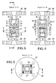
- FIG. 1-3 illustrate a flow display device according to the invention, consisting of a flow housing 4 with an essentially circular cylindrical flow chamber 3, in which an impeller 5 is rotatably mounted.
- the flow chamber 3 is equipped with an inlet channel 1 and an outlet channel 2.
- the centers of the inlet opening 7 of the inlet channel 1 of the flow chamber 3 and the outlet opening 8 of the outlet channel 2 of the flow chamber 3 are at a circumferential distance from one another which is less than 180 °.
- Inlet duct 1 and outlet duct 2 are in flow connection with housing openings 9, 10 lying on opposite end faces 12, 13 of the flow housing 4.
- the housing openings 9, 10 for inlet duct 1 and outlet duct 2 are located centrally in the opposite end faces 12, 13 of the flow housing 4. From the housing opening 9, the inlet duct 1 leads obliquely to the radial direction by means of the inlet opening 7 into the lateral surface 11 of the flow duct 3.
- the outlet channel 2 leads obliquely to the radial direction away from the outlet opening 8 from the lateral surface 11 of the flow chamber 3.
- a nozzle disk 14 equipped with an external thread is screwed, which has a nozzle bore 15 of a predetermined cross section.
- the nozzle disk 14 has two engagement openings on the outside for a turning tool.
- the central longitudinal axis 16 of the nozzle bore 15, like that of the inlet channel 1 is directed towards the radially outer end sections 17 of the vanes 6 of the impeller 5 passing the inlet opening 7.
- the blades 6 of the impeller 5 can, as indicated in Fig. 1, also be broken.
- the radially outer end sections 17 of the blades 6 of the impeller 5 keep the smallest possible distance from the lateral surface 11 of the flow chamber 3, so that the smallest possible fluid leakage takes place on the lateral surface 11.
- the impeller 5 is rotatably received on a shaft 23 which is rotatably supported in the two opposite flat side walls 22, 24 of the flow housing 4.
- the bearing for the shaft 23 is formed by a bearing element 25, 26 which is axially fixed in one side wall 22 and which is axially adjustable in the other side wall 24 from the outside.
- Both flat side walls 22, 24 of the flow housing 4 are each formed by a housing cover 17, 28 which is removably fastened by means of screws 55.
- the housing cover 27, 28 can consist of transparent material.
- the housing covers 27, 28 protrude into a recess in the side walls 22, 24 with an extension 51, 52 which receive the bearing elements 25, 26 for the shaft 23 of the impeller 5.
- There the lugs 51, 52 are radially sealed against the flow housing 4 by means of a sealing ring 53, 54.
- Inlet duct 1 and outlet duct 2 are provided with connecting sleeves 29, 30.
- the connecting sleeves 29, 30 are sealingly inserted with a sleeve section 31, 32 by means of a sealing ring 33 into a non-threaded bore of the inlet channel 1 or outlet channel 2.
- the respective sleeve section 31, 32 has a recess 34 with a round groove base, the two corresponding recesses 36, each formed by a section of two externally accessible housing bores 35, opposite the threadless bore of the inlet channel 1 and the outlet channel 2.
- a locking pin 37 designed as a threaded pin is inserted into the housing bores 35. In this way, the connecting sleeves 29, 30 are fixed axially, but rotatable relative to the flow housing 4.
- the flow display device according to FIGS. 4-6 differs from that in FIGS. 1-3 essentially only in that the connecting sleeves 29 ', 30' for inlet channel 1 and outlet channel 2 do not have an internal thread 56 for a pipe screw connection, but a flange 57, 58 for a flange connection.
- the connecting sleeves 29 ', 30' are welded to the flow housing 4 in this case.
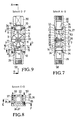
- the embodiment of the device according to FIGS. 7-9 is similar to that from FIGS. 1-3.
- the device is equipped as a flow meter, which does not only provide an optical flow indicator due to the transparent material of the one housing cover 27 offers (a housing cover 28 is missing here), but also an electrical measurement display for the flow rate or the flow.
- the impeller 5 has a number of magnets, ferrite cores or the like arranged in the circumferential distance from one another.
- the sector disk 20 forms part of the hub 21 of the impeller 5.
- the pulse-generating elements 18 are arranged directly adjacent to the flat side wall 22 of the flow housing 4, on the outside of which there is a Hall generator (not shown), a coil (not shown) or a proximity switching element (not shown) for the generation of an electrical voltage or current signal is arranged.
- a Hall generator not shown
- a coil not shown
- a proximity switching element not shown
- connection sleeves 29, 30 provided for a threaded connection are replaced by connection sleeves 29 'and 30' with flanges which with the flow housing 4 are welded, similar to the embodiment of FIGS. 4-6. Otherwise, the structure is identical.
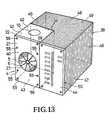
- Fig. 13 shows an oblique view of an overall device with flow housing 4, which is fitted into the recess 38 of the device housing 39 and integrated with it to form a compact overall shape.
- the connecting sleeves 29, 30 and 29 ', 30' are not shown.
- the housing cover 27 is made of transparent material, so that the device can be used both as a flow indicator and as a flow meter using the electronic circuit that is housed in the device housing 39.
- the recess 38 of the device housing 39 is cuboid-shaped in accordance with the outer shape of the flow housing 4 such that the exposed outer surfaces 40-43 of the flow housing 4 are aligned with the adjacent outer surfaces 44-47 of the device housing 39.
- the side wall 22 of the flow housing 4 is in particular flush with the frontal outer surface 44 of the device housing 39.
- the flow housing 4 is also thermally insulated from the device housing 39 in that heat-insulating plates are placed between the flow housing 4 and the device housing 39.
- the frontal outer surface 44 of the device housing 39 is equipped with an exchangeable scale field plate 50, from which the analog or digital display of the flow rate or the flow takes place, for example by means of light-emitting diodes.
- additional functions such as reaching or exceeding a predetermined limit value, the operating state (on / off) of the device, the signal range (in mA) and actuators for setting the measuring range and the like can also be displayed.
- a predetermined limit value the operating state (on / off) of the device
- the device housing 39 is designed as a section of an extruded hollow profile and its outer surfaces 40-49 are profiled, for example with ribs or grooves which run in the longitudinal direction of the extruded profile.
Landscapes
- Physics & Mathematics (AREA)
- General Physics & Mathematics (AREA)
- Fluid Mechanics (AREA)
- Engineering & Computer Science (AREA)
- Aviation & Aerospace Engineering (AREA)
- Electromagnetism (AREA)
- Measuring Volume Flow (AREA)
Abstract
Description
Die Erfindung bezieht sich auf ein Strömungsanzeige- bzw. -meßgerät mit einem in einer im wesentlichen kreiszylindrischen, einen Einlaßkanal und einen Auslaßkanal aufweisenden Strömungskammer eines Strömungsgehäuses drehbar gelagerten Flügelrad.The invention relates to a flow display or measuring device with an impeller which is rotatably mounted in an essentially circular-cylindrical flow chamber of a flow housing and has an inlet channel and an outlet channel.
Derartige Strömungsanzeige- bzw. -meßgeräte sind an sich bekannt. Sie liefern entweder eine unmittelbare Strömungsanzeige dadurch, daß das sich bei Strömung drehende Flügelrad von außen sichtbar ist, oder sie dienen als Strömungsmeß-, Zähl- oder Dosiergerät, indem das Flügelrad an den Enden der Flügel mit abwechselnd gepolten Magneten ausgerüstet ist, welche in einer ortsfesten Aufnahmespule Spannungsimpulse auslösen. Diese elektrischen Impulse können in einer elektronischen Schaltung verstärkt und gezählt werden, woraus sich die Durchflußmenge bzw. der Durchfluß ermitteln und an einer Anzeigetafel in Liter bzw. Liter/Minute mittels Leuchtdioden anzeigen läßt. Derartige Flügelrad-Strömungsanzeige- bzw. -meßgeräte haben bspw. gegenüber einigen Schwebekörper-Durchflußmessern den Vorteil eines nahezu viskositätsunabhängigen Anzeige- bzw. Meßergebnisses. Die bekannten Geräte dieser Art und jedoch in ihrer Einsatzdauer bei zuverlässiger Funktion verhältnismäßig beschränkt und nehmen als Strömungsmeßgerät mit Gerätegehäuse für die elektronische Schaltung verhältnismäßig viel Platz ein. Ferner ist ihr Strömungswiderstand, da Einlaßkanal und Auslaßkanal in ein und derselben Seitenwand liegen, verhältnismäßig groß.Such flow indicators or measuring devices are known per se. They either provide an immediate flow indication by the fact that the rotating impeller is visible from the outside, or they serve as a flow measuring, counting or metering device in that the impeller is equipped at the ends of the blades with alternately polarized magnets, which are in a Fixed pickup coil trigger voltage pulses. These electrical impulses can be amplified and counted in an electronic circuit, from which the flow rate or the flow rate can be determined and displayed on a display board in liters or liters / minute by means of LEDs. Such impeller flow indicators or measuring devices have, for example, the advantage of a virtually viscosity-independent display or measurement result compared to some variable area flowmeters. The well-known devices of this type and, however, relatively limited in their period of use with reliable function and take up a relatively large amount of space as a flow meter with a device housing for the electronic circuit. Furthermore, their flow resistance is relatively large, since the inlet duct and outlet duct lie in one and the same side wall.
Hiervon ausgehend ist es Aufgabe der vorliegenden Erfindung, ein Strömungsanzeige- bzw. -meßgerät der eingangs genannten Art so auszubilden, daß es für lange Betriebsdauern voll funktionsfähig und von der gewünschten Meßgenauigkeit für einen weiten Meßbereich ist.Proceeding from this, it is an object of the present invention to design a flow indicator or meter of the type mentioned at the outset in such a way that it is fully functional for long operating times and of the desired measuring accuracy for a wide measuring range.
Diese Aufgabe wird erfindungsgemäß im wesentlichen dadurch gelöst, daß das Flügelrad eine ungerade Anzahl von Flügeln hat.This object is essentially achieved in that the impeller has an odd number of blades.
Bei den bekannten Geräten, welche mit Magneten wechselnder Polarität in den Flügeln des Flügelrades ausgestattet sind, ist eine gerade Anzahl von Flügeln erforderlich. Dies kann zu unerwünschten Resonanzen und Anlaufschwierigkeiten des Flügelrades führen. Die Resonanzen führen zu einer erheblichen Beanspruchung der Lagerung des Flügelrades, welche noch dadurch erhöht wird, daß die durch die Magneten bedingte träge Masse des Flügelrades in verhältnismäßig großem radialem Abstand von der Drehachse liegt.In the known devices, which are equipped with magnets of alternating polarity in the vanes of the impeller, an even number of vanes is required. This can lead to undesired resonances and starting difficulties of the impeller. The resonances lead to a considerable stress on the bearing of the impeller, which is further increased by the fact that the inertial mass of the impeller caused by the magnets lies at a relatively large radial distance from the axis of rotation.
Um ferner den Strömungswiderstand des neuen Gerätes zu verringern, liegen die Mittelpunkte der Einlaßöffnung des Einlaßkanals der Strömungskammer und Auslaßöffnung des Auslaßkanals der Strömungskammer vorzugsweise in einem Umfangsabstand von nur etwa 180° oder weniger, vorzugsweise in einem Umfangsabstand zwischen 180° und 160°.To further reduce the flow resistance of the new device, the centers of the inlet opening of the inlet channel of the flow chamber and outlet opening of the outlet channel of the flow chamber are preferably at a circumferential distance of only about 180 ° or less, preferably at a circumferential distance between 180 ° and 160 °.
Dabei stehen bei einer weiteren Ausgestaltung der Erfindung Einlaßkanal und Auslaßkanal vorzugsweise mit auf einander gegenüberliegenden Stirnseiten des Strömungsgehäuses liegenden Gehäuseöffnungen in Strömungsverbindung.In a further embodiment of the invention, the inlet duct and outlet duct are preferably in flow connection with housing openings lying on opposite end faces of the flow housing.
Anlaufschwierigkeiten des Flügelrades können mit Sicherheit dann vermieden werden, wenn wenigstens der Einlaßkanal schräg zur Radialrichtung, vorzugsweise unter einem Winkel zwischen 10° und 80° zur Radialrichtung, in die Mantelfläche der Strömungskammer mündet. Dadurch wird nämlich trotz kompakter Bauweise gewährleistet, daß die Strömung mit Sicherheit mit einer Komponente senkrecht zu einem Flügel des Flügelrades auf diesen Flügel auftrifft.Start-up difficulties of the impeller can be avoided with certainty if at least the inlet channel opens into the lateral surface of the flow chamber at an angle to the radial direction, preferably at an angle between 10 ° and 80 ° to the radial direction. This ensures in spite of the compact design that the flow surely strikes this wing with a component perpendicular to a wing of the impeller.
Auch der Auslaßkanal kann schräg zur Radialrichtung, vorzugsweise unter einem Winkel zwischen 10° und 80° zur Radialrichtung, aus der Mantelfläche der Strömungskammer wegführen. Bei einem so ausgestatteten Gerät kann das zu messende Fluid je nach den Platzverhältnissen entweder von der einen oder der anderen Seite aus durch die Strömungskammer geführt werden.The outlet channel can also lead away from the lateral surface of the flow chamber at an angle to the radial direction, preferably at an angle between 10 ° and 80 ° to the radial direction. With a device equipped in this way, the fluid to be measured can be guided through the flow chamber either from one side or the other, depending on the space available.
Um günstige Strömungsverhältnisse zu erzielen, wird weiterhin mit der Erfindung vorgeschlagen, die Gehäuseöffnungen für Einlaßkanal und/oder Auslaßkanal mittig in den einander gegenüberliegenden Stirnseiten des Strömungsgehäuses vorzusehen.In order to achieve favorable flow conditions, it is further proposed with the invention to provide the housing openings for the inlet duct and / or outlet duct centrally in the opposite end faces of the flow housing.
Eine hohe Meßgenauigkeit für einen weiten Meßbereich kann man dann erzielen, wenn gemäß einem weiteren Erfindungsmerkmal in den Einlaßkanal und/oder den Auslaßkanal eine Düsenscheibe einsetzbar, z.B. einschraubbar ist, welche eine Düsenbohrung vorbestimmten Querschnitts aufweist. Die Düsenscheibe ist damit auf einfache Weise gegen eine andere Düsenscheibe mit einem anderen Düsenbohrungsquerschnitt austauschbar.A high measuring accuracy for a wide measuring range can be achieved if, according to a further feature of the invention, a nozzle disk can be inserted, for example screwed, into the inlet channel and / or the outlet channel, which has a nozzle bore of a predetermined cross-section. The nozzle disk is thus easily exchangeable for another nozzle disk with a different cross section of the bore.
Dabei führt vorzugsweise die durch die Mittellängsachse der Düsenbohrung bestimmte Strömungsrichtung in der eingesetzten, z.B. eingeschraubten Lage der Düsenscheibe unabhängig von der Richtung des Einlaßkanals schräg zur Radialrichtung, vorzugsweise unter einem Winkel zwischen 10° und 80° zur Radialrichtung, in die (gedachte) Mantelfläche der Strömungskammer, so daß ein Anlaufen des Flügelrades stets sicher gewährleistet ist.The flow direction determined by the central longitudinal axis of the nozzle bore preferably leads in the direction used, e.g. screwed position of the nozzle disc regardless of the direction of the inlet channel obliquely to the radial direction, preferably at an angle between 10 ° and 80 ° to the radial direction, in the (imaginary) lateral surface of the flow chamber, so that a start of the impeller is always guaranteed guaranteed.
Es wird ferner vorgeschlagen, bei einer weiteren Ausgestaltung der Erfindung die Mittellängsachse des Einlaßkanals bzw. der Düsenbohrung auf die radial äußeren Endabschnitte der vorbeilaufenden Flügel des Flügelrades zu richten, um ein großes Drehmoment auf das Flügelrad auszuüben.It is further proposed, in a further embodiment of the invention, to direct the central longitudinal axis of the inlet channel or the nozzle bore onto the radially outer end sections of the passing vanes of the impeller in order to exert a large torque on the impeller.
Radial innerhalb der radial äußeren Endabschnitte der Flügel können die Flügel des Flügelrades durchbrochen sein, wodurch die Masse des Flügelrades und der Widerstand beim Verdrehen innerhalb der gefüllten Strömungskammer verringert werden.The vanes of the impeller can be perforated radially within the radially outer end sections of the vanes, as a result of which the mass of the impeller and the resistance when rotating within the filled flow chamber are reduced.
Die radial äußeren Endabschnitte der Flügel des Flügelrades haben einen möglichst geringen Abstand von jedenfalls unter einem Millimeter, vorzugsweise unter 0,5 mm von der Mantelfläche der Strömungskammer, so daß sie fast abdichten. Hierdurch wird die Zähl- bzw. Meßgenauigkeit wegen geringer Leckage erhöht.The radially outer end sections of the vanes of the impeller have the smallest possible distance of at least less than one millimeter, preferably less than 0.5 mm, from the outer surface of the flow chamber, so that they almost seal. As a result, the counting or measuring accuracy is increased due to low leakage.
Damit das Gerät nicht nur als Strömungsanzeige-, sondern auch als Strömungsmeßgerät eingesetzt werden kann, weist das Flügelrad eine Anzahl von im Unfangsabstand voneinander angeordneten Magneten, Ferritkernen od. dgl. impulsgebenden Elementen auf. Im Gegensatz zum Stand der Technik, bei welchen die Magnete an den radial äußeren Enden der Flügel vorgesehen sind, befinden sich erfindungsgemäß die impuls gebenden Elemente vorzugsweise in Nachbarschaft zur Achse des Flügelrades. Hierdurch wird das Trägheitsmoment des Flügelrades erheblich verringert. Die Lager werden dadurch weniger belastet. Außerdem sind die Magnete nicht in den Flügeln oder gar deren Enden vorgesehen, so daß trotz der ungeraden Anzahl von Flügeln eine gerade Anzahl von Magneten mit wechselnder Polarität für das Zusammenwirken mit einem ortsfesten Hall-Sensor oder von Ferritkernen für das Zusammenwirken mit einer ortsfesten Spule vorgesehen werden können.So that the device can be used not only as a flow indicator but also as a flow measuring device, the impeller has a number of magnets, ferrite cores or the like arranged at a circumferential distance from one another. In contrast to the prior art, in which the magnets are provided at the radially outer ends of the vanes, the pulses are according to the invention giving elements preferably in the vicinity of the axis of the impeller. This significantly reduces the moment of inertia of the impeller. The bearings are thus less stressed. In addition, the magnets are not provided in the wings or even the ends thereof, so that despite the odd number of wings, an even number of magnets with alternating polarity are provided for interaction with a stationary Hall sensor or of ferrite cores for interaction with a stationary coil can be.
Die impulsgebenden Elemente sind dabei vorzugsweise in einer Sektorscheibe zusammengefaßt, wobei in jedem Sektor ein impulsgebendes Element angeordnet ist.The pulse-generating elements are preferably combined in a sector disk, with a pulse-generating element being arranged in each sector.
Die Sektorscheibe kann ein Teil der Nabe des Flügelrades bzw. mit dieser drehfest verbunden sein.The sector disk can be part of the hub of the impeller or connected to it in a rotationally fixed manner.
Ferner ist es von Vorteil, wenn die impulsgebenden Elemente benachbart einer flachseitigen Seitenwand des Strömungsgehäuses angeordnet sind, nämlich benachbart derjenigen Seitenwand, hinter welcher der Hall-Sensor, die Spule oder ein Näherungssensor zur Erzeugung der elektrischen Impulse vorgesehen ist. Auf diese Weise erhält man verhältnismäßig große elektrische Impulse.It is also advantageous if the pulse-generating elements are arranged adjacent to a flat side wall of the flow housing, namely adjacent to the side wall behind which the Hall sensor, the coil or a proximity sensor is provided for generating the electrical pulses. In this way, relatively large electrical impulses are obtained.
Das Flügelrad kann zwar auf einer drehfesten Achse angeordnet sein. Hierfür bedarf es jedoch einer hinreichenden Schmierung. Vorteilhafter ist es, wenn erfindungsgemäß das Flügelrad drehfest auf einer Welle aufgenommen ist, welche in den beiden einander gegenüberliegenden flachseitigen Seitenwänden des Strömungsgehäuses drehbar gelagert ist.The impeller can be arranged on a rotationally fixed axis. However, sufficient lubrication is required for this. It is more advantageous if, according to the invention, the impeller is rotatably received on a shaft which is rotatably mounted in the two opposite flat side walls of the flow housing.
Die Lagerung für die Welle wird gemäß einem weiteren Erfindungsmerkmal von einem in einer Seitenwand axial festliegenden und einem in der anderen Seitenwand, vorzugsweise von außen, axial verstellbaren Lagerelement gebildet. Auf diese Weise ist eine schnelle und sichere Montage des Flügelrades bei langdauernder Funktionsfähigkeit gewährleistet.According to a further feature of the invention, the bearing for the shaft is provided by one axially fixed in one side wall and one in the other side wall, preferably by formed outside, axially adjustable bearing element. In this way, a quick and safe assembly of the impeller with long-term functionality is guaranteed.
Der einfachen Montage dient es auch, wenn wenigstens eine der flachseitigen Seitenwände des Strömungsgehäuses wenigstens teilweise von einem abnehmbar befestigten Gehäusedeckel gebildet ist, wie dies an sich bekannt ist.The simple assembly also serves if at least one of the flat side walls of the flow housing is at least partially formed by a detachably fastened housing cover, as is known per se.
Wenigstens eine der flachseitigen Seitenwände, die parallel zu dem Flügelrad liegen und vorzugsweise die Lagerelemente für das Flügelrad aufnehmen, bzw. wenigstens einer der Gehäusedeckel, welche die gleiche Lage und Funktion haben, besteht aus durchsichtigem Material, so daß das sich bei Vorliegen einer Störmung drehende Flügelrad von außen sichtbar ist und damit eine Strömungsanzeige ohne elektronische Schaltung gegeben wird. Sind beide Seitenwände bzw. Gehäusedeckel durchsichtig, kann von beiden Seiten aus optisch festgestellt werden, ob in der Leitung, in welche das Strömungsgehäuse eingeschaltet ist, eine Strömung herrscht oder nicht.At least one of the flat side walls, which are parallel to the impeller and preferably accommodate the bearing elements for the impeller, or at least one of the housing covers, which have the same position and function, is made of transparent material, so that the rotating in the presence of a malfunction Impeller is visible from the outside and thus a flow indicator is given without electronic circuit. If both side walls or the housing cover are transparent, it can be optically determined from both sides whether there is a flow in the line into which the flow housing is switched on or not.
Eine zuverlässige Abdichtung des Strömungsgehäuses erhält man bei einfacher Montage dann, wenn die Gehäusedeckel mit einem Ansatz in eine Aussparung der Seitenwände hineinragen und dort mittels eines Dichtungsringes radial abgedichtet sind.A reliable sealing of the flow housing can be obtained with simple assembly if the housing covers protrude into a recess in the side walls and are radially sealed there by means of a sealing ring.
Das erfindungsgemäße Strömungsgehäuse kann Anschlußmuffen für den Einlaßkanal bzw. den Auslaßkanal aufweisen, die entweder einen Rohranschluß über Gewinde oder über Flansch zulassen. Um einen einfachen Einbau eines Rohranschlusses über Gewinde zuzulassen, sind sie an ihrem äußeren Ende bspw. mit einem Innengewinde ausgestatteten Anschlußmuffen mit einem Muffenabschnitt mittels Dichtungsring in eine gewindelose Bohrung des Einlaßkanals bzw. Auslaßkanals dichtend eingesetzt und der Muffenabschnitt hat einen Einstich mit rundem Nutgrund, dem ein entsprechender von einem Abschnitt wenigstens einer von außen zugänglichen Gehäusebohrung gebildeter Einstich der gewindelosen Bohrung gegenüberliegt. In die jeweilige Gehäusebohrung ist dann ein z.B. als Gewindestift ausgebildeter Sicherungsstift eingesetzt. Auf diese Weise werden die Anschlußmuffen axial unverrückbar, jedoch drehbar an dem Strömungsgehäuse gehalten, wodurch auf einfache Weise eine Schraubverbindung zu der Anschlußleitung hergestellt werden kann. Auch während des Betriebes des Gerätes können die Anschlußmuffen relativ zu dem Strömungsgehäuse bewegt werden, ohne daß die Dichtigkeit der Anschlußmuffen beeinträchtigt wird. Hiermit wird ein weiterer konstruktiver und funktioneller Vorteil erreicht.The flow housing according to the invention can have connection sleeves for the inlet channel or the outlet channel, which either allow a pipe connection via thread or via flange. In order to allow easy installation of a pipe connection via thread, they are inserted at their outer end, for example with an internal thread, connecting sleeves with a sleeve section by means of a sealing ring into a threadless bore of the inlet channel or outlet channel, and the sleeve section has a recess with a round groove base, which is opposite a corresponding recess formed by a section of at least one externally accessible housing bore of the unthreaded bore. A locking pin, for example a threaded pin, is then inserted into the respective housing bore. In this way, the connection sleeves are held axially immovable, but rotatably, on the flow housing, as a result of which a screw connection to the connection line can be produced in a simple manner. Even during operation of the device, the connection sleeves can be moved relative to the flow housing without the tightness of the connection sleeves being impaired. A further constructive and functional advantage is hereby achieved.
Um ein möglichst kompaktes Gerät zu erhalten, ist in weiterer Ausgestaltung das Strömungsgehäuse in einer Aussparung eines Gerätegehäuses eingepaßt, welches für die Aufnahme der elektronischen Schaltung bestimmt ist.In order to obtain a device which is as compact as possible, in a further embodiment the flow housing is fitted into a recess in a device housing which is intended to accommodate the electronic circuit.
Die äußere Gestalt des Strömungsgehäuses ist dabei vorzugsweise im wesentlichen quaderförmig ausgebildet und in der in das Gerätegehäuse eingesetzten Lage des Strömungsgehäuses fluchten vorzugsweise die freiliegenden Außenflächen des Strömungsgehäuses mit den angrenzenden Außenflächen des Gerätegehäuses. Dadurch wird ein kompaktes Gesamtgerät mit ineinander übergehenden Außenflächen geschaffen. Soll lediglich eine Strömungsanzeige erfolgen, kann das Strömungsgehäuse mit Flügelrad und Anschlußmuffen selbständig verwendet werden. Soll das Gerät aber (auch) als Strömungsmeßgerät dienen, wird es somit in das Gerätegehäuse des Gesamtgehäuses integriert. Diese Integration ist auch nachträglich möglich, wenn von einer rein visuellen Anzeige einer Strömung eine Messung der Durchflußmenge bzw. des Durchflusses mittels der Magnete, Ferrite od. dgl. impulsgebenden Elemente und einer elektronischen Schaltung erfolgen und eine Anzeige über Leuchtdioden und/oder Digitalsignale erfolgen soll.The outer shape of the flow housing is preferably essentially cuboid and in the position of the flow housing inserted into the device housing the exposed outer surfaces of the flow housing are preferably flush with the adjacent outer surfaces of the device housing. This creates a compact overall device with merging outer surfaces. If only a flow indicator is to be used, the flow housing with impeller and connecting sleeves can be used independently. However, if the device is also to serve as a flow measuring device, it is thus integrated into the device housing of the overall housing. This integration is also possible retrospectively if, from a purely visual display of a flow, the flow rate or the flow is measured by means of the magnets, ferrites or the like. Impulse-generating elements and an electronic circuit and a display via light-emitting diodes and / or digital signals is to take place .
Bei der Integration des Strömungsgehäuses in das Gerätegehäuse wird insbesondere vorgeschlagen, daß die Außenfläche der einen flächenseitigen Seitenwand des Strömungsgehäuses mit der frontalen Außenfläche des Gerätegehäuses fluchtet. Die betreffende flächenseitige Seitenwand des Strömungsgehäuses bzw. der sie bildende Gehäusedeckel sind dabei vorzugsweise aus durchsichtigem Material, so daß das Gerät nicht nur zur Durchflußmengenmessung bzw. Durchflußmessung, sondern auch zur bloßen visuellen Strömungsanzeige verwendet werden kann.When integrating the flow housing into the device housing, it is proposed in particular that the outer surface of the one side wall of the flow housing is flush with the front outer surface of the device housing. The relevant side wall of the flow housing or the housing cover forming it are preferably made of transparent material, so that the device can be used not only for flow rate measurement or flow measurement, but also for mere visual flow display.
Da die elektronische Schaltung Temperaturen über 100°C nicht ausgesetzt werden sollte, die zu messenden Fluide aber z.T. höhere Temperaturen haben können, wird bei einer Integration des Strömungsgehäuses in das Gerätegehäuse weiterhin vorgeschlagen, daß das Strömungsgehäuse in der in das Gerätegehäuse eingesetzten Lage gegen das Gerätegehäuse thermisch isoliert ist, bspw. durch Zwischenlage von thermisch isolierenden Platten.Since the electronic circuit should not be exposed to temperatures above 100 ° C, some of the fluids to be measured. when the flow housing is integrated into the device housing, it is further proposed that the flow housing is thermally insulated from the device housing in the position inserted into the device housing, for example by interposing thermally insulating plates.
Um das erfindungsgemäße Gerät einfach auf unterschiedliche Meßbereiche umstellen zu können, kann die frontale Außenfläche des Gerätegehäuses mit einer auswechselbaren Skalenfeldplatte ausgestattet sein.In order to be able to easily convert the device according to the invention to different measuring ranges, the front outer surface of the device housing can be equipped with an exchangeable scale field plate.
Eine einfache Herstellung und Montage des Gerätes wird dadurch gewährleistet, daß das Gerätegehäuse als Abschnitt eines Stranghohlprofils ausgebildet ist.A simple manufacture and assembly of the device is ensured in that the device housing is designed as a section of an extruded hollow profile.
Damit ein Überschreiten der maximalen Temperatur in den Gerätegehäuse möglichst verhindert wird, können die Außenflächen des Gerätegehäuses profiliert, z.B. mit Rippen oder Nuten ausgestaltet sein, welche in Stranprofillängsrichtung verlaufen, so daß die einzelnen Gerätegehäuse einfach von dem fortlaufenden Hohlprofilstrang abgeschnitten werden können.To prevent the maximum temperature in the device housing from being exceeded as far as possible, the outer surfaces of the device housing can be profiled, for example designed with ribs or grooves which run in the longitudinal direction of the extruded profile, so that the individual device housings can simply be cut off from the continuous hollow profile strand.
Weitere Ziele, Merkmale, Vorteile und Anwendungsmöglichkeiten der vorliegenden Erfindung ergeben sich aus der nachfolgenden Beschreibung von Ausführungsbeispielen anhand der beiliegenden Zeichnung. Dabei bilden alle beschriebenen und/oder bildlich dargestellten Merkmale für sich oder in beliebiger sinnvoller Kombination den Gegenstand der vorliegenden Erfindung auch unabhängig von ihrer Zusammenfassung in den Ansprüchen oder deren Rückbeziehung.Further objectives, features, advantages and possible uses of the present invention result from the following description of exemplary embodiments with reference to the attached drawing. All of the described and / or illustrated features, alone or in any meaningful combination, form the subject matter of the present invention, regardless of how they are summarized in the claims or their relationship.
Es zeigen:
- Fig. 1 eine Ausführungsform des erfindungsgemäßen Gerätes im Vertikalschnitt A-B von Fig. 3,
- Fig. 2 das Gerät gemäß Fig. 1 in einem Horizontalschnitt C-D von Fig. 3,
- Fig. 3 einen Vertikalschnitt E-F des erfindungsgemäßen Gerätes gemäß Fig. 2,
- Fig. 4 eine Schnittdarstellung entsprechend Fig. 1 einer anderen Ausführungsform eines erfindungsgemäßen Gerätes (Schnitt A-B von Fig. 6),
- Fig. 5 einen Horizontalschnitt C-D gemäß Fig. 6 des erfindungsgemäßen Gerätes von Fig. 4,
- Fig. 6 einen Vertikalschnitt C-D von Fig. 5 des erfindungsgemäßen Gerätes gemäß Fig. 4,
- Fig. 7 ein als Strömungsmeßgerät ausgebildetes Gerät im Vertikalschnitt A-B von Fig. 9,
- Fig. 8 einen Horizontalschnitt E-F von Fig. 8 des erfindungsgemäßen Gerätes gemäß Fig. 7,
- Fig. 9 einen Vertikalschnitt E-F von Fig. 8 des erfindungsgemäßen Gerätes von Fig. 7,
- Fig. 10 einen Vertikalschnitt A-B entsprechend Fig. 7 für eine andere Ausführungsform eines erfindungsgemäßen, als Strömungsmeßgerät ausgebildeten Gerätes,
- Fig. 11 einen Horizontalschnitt C-D von Fig. 12 eines erfindungsgemäßen Gerätes von Fig. 10,
- Fig. 12 einen Vertikalschnitt E-F von Fig. 11 eines erfindungsgemäßen Gerätes nach Fig. 10, und
- Fig. 13 eine Schrägansicht eines erfindungsgemäßen Strömungsanzeige- und -meßgerätes, bei welchem das Strömungsgehäuse in eine Aussparung des Geräteg ehäuses zur Schaffung eines Kompaktgerätes eingesetzt ist.
- 1 shows an embodiment of the device according to the invention in vertical section AB of FIG. 3,
- 2 shows the device according to FIG. 1 in a horizontal section CD from FIG. 3,
- 3 shows a vertical section EF of the device according to the invention according to FIG. 2,
- 4 shows a sectional view corresponding to FIG. 1 of another embodiment of a device according to the invention (section AB of FIG. 6),
- 5 shows a horizontal section CD according to FIG. 6 of the device according to the invention from FIG. 4,
- 6 shows a vertical section CD of FIG. 5 of the device according to the invention according to FIG. 4,
- 7 shows a device designed as a flow measuring device in vertical section AB from FIG. 9,
- 8 is a horizontal section EF of FIG. 8 of the device according to the invention according to FIG. 7,
- 9 shows a vertical section EF from FIG. 8 of the device according to the invention from FIG. 7,
- 10 shows a vertical section AB corresponding to FIG. 7 for another embodiment of a device according to the invention designed as a flow measuring device,
- 11 is a horizontal section CD of FIG. 12 of an apparatus according to the invention from FIG. 10,
- Fig. 12 is a vertical section EF of Fig. 11 of an inventive device according to Fig. 10, and
- Fig. 13 is an oblique view of a flow indicator and meter according to the invention, in which the flow housing is inserted into a recess of the device housing to create a compact device.
Die Fig. 1 - 3 veranschaulichen ein erfindungsgemäßes Strömungsanzeigegerät, bestehend aus einem Strömungsgehäuse 4 mit einer im wesentlichen kreiszylindrischen Strömungskammer 3, in welcher ein Flügelrad 5 drehbar gelagert ist. Die Strömungskammer 3 ist mit einem Einlaßkanal 1 und einem Auslaßkanal 2 ausgestattet. Die Mittelpunkte der Einlaßöffnung 7 des Einlaßkanals 1 der Strömungskammer 3 der und Auslaßöffnung 8 des Auslaßkanals 2 der Strömungskammer 3, liegen in einem Umfangsabstand voneinander, welcher kleiner als 180° ist. Einlaßkanal 1 und Auslaßkanal 2 stehen mit auf einander gegenüberliegenden Stirnseiten 12, 13 des Strömungsgehäuses 4 liegenden Gehäuseöffnungen 9, 10 in Strömungsverbindung. Die Gehäuseöffnungen 9, 10 für Einlaßkanal 1 und Auslaßkanal 2 liegen mittig in den einander gegenüberliegenden Stirnseiten 12, 13 des Strömungsgehäuses 4. Von der Gehäuseöffnung 9 führt der Einlaßkanal 1 schräg zur Radialrichtung mittels der Einlaßöffnung 7 in die Mantelfläche 11 des Strömungskanals 3.1-3 illustrate a flow display device according to the invention, consisting of a
Der Auslaßkanal 2 führt schräg zur Radialrichtung von der Auslaßöffnung 8 aus der Mantelfläche 11 der Strömungskammer 3 weg. In den mit einem Innengewinde ausgestatteten Einlaßkanal 1 ist eine mit einem Außengewinde ausgestattete Düsenscheibe 14 eingeschraubt, welche eine Düsenbohrung 15 vorbestimmten Querschnitts aufweist. Die Düsenscheibe 14 hat außenseitig zwei Eingriffsöffnungen für ein Drehwerkzeug. Dabei ist die Mittellängsachse 16 der Düsenbohrung 15 wie die des Einlaßkanals 1 selbst auf die radial äußeren Endabschnitte 17 der an der Einlaßöffnung 7 vorbeilaufenden Flügel 6 des Flügelrades 5 gerichtet. Dabei können die Flügel 6 des Flügelrades 5, wie in Fig. 1 angedeutet, auch durchbrochen sein. Die radial äußeren Endabschnitte 17 der Flügel 6 des Flügelrades 5 halten einen möglichst geringen Abstand von der Mantelfläche 11 der Strömungskammer 3, so daß eine möglichst geringe Fluidleckage an der Mantelfläche 11 stattfindet.The
Das Flügelrad 5 ist drehfest auf einer Welle 23 aufgenommen, welche in den beiden einander gegenüberliegenden flachseitigen Seitenwänden 22, 24 des Strömungsgehäuses 4 drehbar gelagert ist. Die Lagerung für die Welle 23 ist von einem in einer Seitenwand 22 axial festliegenden und einer in der anderen Seitenwand 24 von außen axial verstellbaren Lagerelement 25, 26 gebildet. Beide flachseitigen Seitenwände 22, 24 des Strömungsgehäuses 4 sind je von einem abnehmbar mittels Schrauben 55 befestigten Gehäusedeckel 17, 28 gebildet. Die Gehäusedeckel 27, 28 können aus durchsichtigem Material bestehen. Die Gehäusedeckel 27, 28 ragen mit einem Ansatz 51, 52, welche die Lagerelemente 25, 26 für die Welle 23 des Flügelrades 5 aufnehmen, in eine Aussparung der Seitenwände 22, 24 hinein. Dort sind die Ansätze 51, 52 mittels eines Dichtungsringes 53, 54 radial gegen das Strömungsgehäuse 4 abgedichtet.The
Einlaßkanal 1 und Auslaßkanal 2 sind mit Anschlußmuffen 29, 30 versehen. Die Anschlußmuffen 29, 30 sind mit einem Muffenabschnitt 31, 32 mittels Dichtungsring 33 in eine gewindelose Bohrung des Einlaßkanals 1 bzw. Auslaßkanals 2 dichtend eingesetzt. Der jeweilige Muffenabschnitt 31, 32 weist einen Einstich 34 mit rundem Nutgrund auf, dem zwei entsprechende, von je einem Abschnitt zweier von außen zugängliche Gehäusebohrungen 35 gebildete Einstiche 36 der gewindelosen Bohrung des Einlaßkanals 1 bzw. des Auslaßkanals 2 gegenüberliegt. In die Gehäusebohrungen 35 ist je ein als Gewindestift ausgebildeter Sicherungsstift 37 eingesetzt. Auf diese Weise sind die Anschlußmuffen 29, 30 axial festgelegt, jedoch gegenüber dem Strömungsgehäuse 4 drehbar.
Das erfindungsgemäße Strömungsanzeigegerät gemäß Fig. 4 - 6 unterscheidet sich von dem in den Fig. 1 - 3 im wesentlichen nur dadurch, daß die Anschlußmuffen 29′, 30′ für Einlaßkanal 1 und Auslaßkanal 2 kein Innengewinde 56 für eine Rohrverschraubung aufweisen, sondern einen Flansch 57, 58 für eine Flanschverbindung. Außerdem sind die Anschlußmuffen 29′, 30′ in diesem Fall mit dem Strömungsgehäuse 4 verschweißt.The flow display device according to FIGS. 4-6 differs from that in FIGS. 1-3 essentially only in that the connecting sleeves 29 ', 30' for
Die Ausführungsform des Gerätes gemäß den Fig. 7 - 9 ähnelt derjenigen aus den Fig. 1 - 3. In den Fig. 7 - 9 ist das Gerät jedoch als Durchflußmeßgerät ausgestattet, welches nicht nur eine optische Strömungsanzeige aufgrund des durchsichtigen Materials des einen Gehäusedeckels 27 bietet (ein Gehäusedeckel 28 fehlt hier), sondern auch noch eine elekrische Meßanzeige für die Durchflußmenge bzw. den Durchfluß. Zu diesem Zweck weist das Flügelrad 5 eine Anzahl von im Umfangsabstand voneinander angeordneten Magneten, Ferritkernen od. dgl. impulsgebenden Elementen 18 auf, welche in unmittelbarer Nachbarschaft zur Achse 19 des Flügelrades 5 in einer z.B. aus Kunststoff bestehenden Sektorscheibe 20 zusammengefaßt und eingeschlossen sind, wobei in jedem Sektor ein impulsgebendes Element 18 angeordnet ist. Die Sektorscheibe 20 bildet einen Teil der Nabe 21 des Flügelrades 5. Die impulsgebenden Elemente 18 sind unmittelbar benachbart der flachseitigen Seitenwand 22 des Strömungsgehäuses 4 angeordnet, an dessen Außenseite sich ein nicht dargestellter Hall-Generator, eine nicht dargestellte Spule oder ein nicht dargestelles Näherungsschaltelement für die Erzeugung eines elektrischen Spannungs- oder Stromsignals angeordnet ist. Das Strömungsgehäuse 4 kann, wie aus den Fig. 8 und 13 ersichtlich, mittels Schrauben 59 in der Aussparung 38 eines Gerätegehäuses 39 festgelegt sein.The embodiment of the device according to FIGS. 7-9 is similar to that from FIGS. 1-3. In FIGS. 7-9, however, the device is equipped as a flow meter, which does not only provide an optical flow indicator due to the transparent material of the one
Die Ausführungsform eines erfindungsgemäßen Gerätes gemäß den Fig. 10 - 12 entspricht im wesentlichen derjenigen nach den Fig. 7 - 9. Hierbei sind jedoch wieder die für eine Gewindeverbindung vorgesehenen Anschlußmuffen 29, 30 durch Anschlußmuffen 29′ und 30′ mit Flanschen ersetzt, die mit dem Strömungsgehäuse 4 verschweißt sind, ähnlich der Ausführungsform der Fig. 4 - 6. Im übrigen ist der Aufbau identisch.The embodiment of a device according to the invention according to FIGS. 10 - 12 corresponds essentially to that according to FIGS. 7 - 9. Here, however, the
Fig. 13 zeigt in Schrägansicht ein Gesamtgerät mit Strömungsgehäuse 4, welches in die Aussparung 38 des Gerätegehäuses 39 eingepaßt und mit diesem zu einer kompakten Gesamtform integriert ist. Die Anschlußmuffen 29, 30 bzw. 29′, 30′ sind nicht dargestellt. Der Gehäusedeckel 27 besteht aus durchsichtigem Material, so daß das Gerät sowohl als Strömungsanzeigegerät als auch als Strömungsmeßgerät eingesetzt werden kann mit Hilfe der elektronischen Schaltung, die in dem Gerätegehäuse 39 untergebracht ist. Die Aussparung 38 des Gerätegehäuses 39 ist entsprechend der Außenform des Strömungsgehäuses 4 quaderförmig derart ausgebildet, daß die freiliegenden Außenflächen 40 - 43 des Strömungsgehäuses 4 mit den angrenzenden Außenflächen 44 - 47 des Gerätegehäuses 39 fluchten. Die Außenfläche 40 der einen flachseitigen Seitenwand 22 des Strömungsgehäuses 4 fluchtet insbesondere mit der frontalen Außenfläche 44 des Gerätegehäuses 39. Das Strömungsgehäuse 4 ist ferner gegenüber den Gerätegehäuse 39 thermisch isoliert, indem wärmeisolierende Platten zwischen das Strömungsgehäuse 4 und das Gerätegehäuse 39 gelegt sind. Die frontale Außenfläche 44 des Gerätegehäuses 39 ist mit einer auswechselbaren Skalenfeldplatte 50 ausgestattet, von welcher aus die analoge oder digitale Anzeige der Durchflußmenge bzw. des Durchflusses z.B. mittels Leuchtdioden erfolgt. Hierbei können bspw. auch Zusatzfunktionen, wie Erreichen bzw. Überschreiten eines vorgegebenen Grenzwertes, der Betriebszustand (Ein/Aus) des Gerätes, der Signalbereich (in mA) angezeigt werden, sowie Betätigungsorgane für die Einstellung des Meßbereiches u. dgl. vorgesehen sein.Fig. 13 shows an oblique view of an overall device with
Das Gerätegehäuse 39 ist als Abschnitt eines Stranghohlprofils ausgebildet und seine Außenflächen 40 - 49 sind profiliert, z.B. mit Rippen oder Nuten, welche in Hohlprofilstranglängsrichtung verlaufen.The
- 1 Einlaßkanal1 inlet duct
- 2 Auslaßkanal2 outlet duct
- 3 Strömungskammer3 flow chamber
- 4 Strömungsgehäuse4 flow housing
- 5 Flügelrad5 impeller
- 6 Flügel6 wings
- 7 Einlaßöffnung7 inlet opening
- 8 Auslaßöffnung8 outlet opening
- 9 Gehäuseöffnung9 housing opening
- 10 Gehäuseöffnung10 housing opening
- 11 Mantelfläche11 lateral surface
- 12 Stirnseite12 end face
- 13 Stirnseite13 end face
- 14 Düsenscheibe14 nozzle disc
- 15 Düsenbohrung15 nozzle bore
- 16 Mittellängsachse16 central longitudinal axis
- 17 Endabschnitte17 end sections
- 18 inpulsgebende Elemente18 stimulating elements
- 19 Achse19 axis
- 20 Sektorscheibe20 sector disk
- 21 Nabe21 hub
- 22 Seitenwand22 side wall
- 23 Welle23 wave
- 24 Seitenwand24 side wall
- 25 Lagerelement25 bearing element
- 26 Lagerelement26 bearing element
- 27 Gehäusedeckel27 housing cover
- 28 Gehäusedeckel28 housing cover
- 29, 29′ Anschlußmuffen29, 29 'connection sleeves
- 30 30′ Anschlußmuffen30 30 'connection sleeves
- 31 Muffenabschnitt31 socket section
- 32 Muffenabschnitt32 socket section
- 33 Dichtungsring33 sealing ring
- 34 Einstich34 puncture
- 35 Gehäusebohrung35 Housing bore
- 36 Einstich36 puncture
- 37 Sicherungsstift37 locking pin
- 38 Aussparung38 recess
- 39 Gerätegehäuse39 device housing
- 40 Außenfläche40 outer surface
- 41 Außenfläche41 outer surface
- 42 Außenfläche42 outer surface
- 43 Außenfläche43 outer surface
- 44 Außenfläche44 outer surface
- 45 Außenfläche45 outer surface
- 46 Außenfläche46 outer surface
- 47 Außenfläche47 outer surface
- 48 Außenfläche48 outer surface
- 49 Außenfläche49 outer surface
- 50 Skalenfeldplatte50 scale field plate
- 51 Ansatz51 approach
- 52 Ansatz52 approach
- 53 Dichtungsring53 sealing ring
- 54 Dichtungsring54 sealing ring
- 55 Schrauben55 screws
- 56 Innengewinde56 internal thread
- 57 Flansch57 flange
- 58 Flansch58 flange
- 59 Schrauben59 screws
Claims (29)
Applications Claiming Priority (2)
| Application Number | Priority Date | Filing Date | Title |
|---|---|---|---|
| DE3733862 | 1987-10-07 | ||
| DE19873733862 DE3733862A1 (en) | 1987-10-07 | 1987-10-07 | FLOW DISPLAY OR MEASURING DEVICE |
Publications (2)
| Publication Number | Publication Date |
|---|---|
| EP0327671A2 true EP0327671A2 (en) | 1989-08-16 |
| EP0327671A3 EP0327671A3 (en) | 1991-02-27 |
Family
ID=6337786
Family Applications (1)
| Application Number | Title | Priority Date | Filing Date |
|---|---|---|---|
| EP19880114321 Withdrawn EP0327671A3 (en) | 1987-10-07 | 1988-09-02 | Flow-indicating or metering device |
Country Status (5)
| Country | Link |
|---|---|
| US (1) | US5099699A (en) |
| EP (1) | EP0327671A3 (en) |
| CA (1) | CA1332519C (en) |
| DE (1) | DE3733862A1 (en) |
| FI (1) | FI884552A (en) |
Families Citing this family (28)
| Publication number | Priority date | Publication date | Assignee | Title |
|---|---|---|---|---|
| DE3918925A1 (en) * | 1989-06-09 | 1990-12-13 | Joseph Voegele Ag | DEVICE FOR ALLOCATING LUBRICANT |
| EP0447811B1 (en) * | 1990-03-12 | 1998-08-26 | Klaus Kobold | Flow monitoring and measuring device |
| DE9017793U1 (en) * | 1990-03-12 | 1992-02-06 | Kobold, Klaus, Dipl.-Ing., 6233 Kelkheim | Flow indicator or measuring device |
| AU2688692A (en) * | 1991-09-23 | 1993-04-27 | Futureflo System, Incorporated | Liquid flow meter |
| DE4311398C2 (en) * | 1993-04-07 | 2000-12-28 | Kobold Klaus | Impeller for flow meters |
| PT718602E (en) * | 1994-12-20 | 2002-12-31 | Schlumberger Ind S R L | SOLID JET LIQUID COUNTER WITH IMPROVED SENSITIVITY AND REGULATORY EFFECT |
| US5549010A (en) * | 1995-01-13 | 1996-08-27 | Ziba Design, Inc. | Readily serviceable ancillary fluid filtration system having visual flow rate indicator and quick-release fluid hose fitting |
| US5876610A (en) * | 1997-03-19 | 1999-03-02 | Clack Corporation | Method and apparatus for monitoring liquid flow through an enclosed stream |
| US5935426A (en) | 1997-08-08 | 1999-08-10 | Teledyne Industries, Inc., A California Corporation | Water treatment device with volumetric and time monitoring features |
| US6149801A (en) * | 1997-08-08 | 2000-11-21 | Water Pik, Inc,. | Water treatment device with volumetric monitoring features |
| US7287398B2 (en) * | 2001-09-25 | 2007-10-30 | Alsius Corporation | Heating/cooling system for indwelling heat exchange catheter |
| DE19958640A1 (en) * | 1999-12-06 | 2001-06-07 | Brita Gmbh | Device for measuring water flow rates |
| EP1116938A1 (en) * | 2000-01-11 | 2001-07-18 | Aqua S.r.l. | Multifunctional filter for waterworks with pressure and flow rate sensors |
| KR100505035B1 (en) * | 2003-11-17 | 2005-07-29 | 삼성전자주식회사 | Electrostatic chuck for supporting a substrate |
| US7104143B1 (en) * | 2005-08-11 | 2006-09-12 | The Boeing Company | Oscillating vane actuator apparatus and method for active flow control |
| US7305893B2 (en) * | 2005-08-11 | 2007-12-11 | The Boeing Company | Oscillating vane actuator apparatus and method for active flow control |
| US7246529B1 (en) | 2006-08-03 | 2007-07-24 | The Boeing Company | Oscillating vane actuator apparatus and method for active flow control |
| DE102006010374A1 (en) * | 2006-03-03 | 2007-09-06 | Mann + Hummel Gmbh | Arrangement of an air mass meter on a flow channel |
| US8069719B2 (en) * | 2009-02-11 | 2011-12-06 | Ecolab Usa Inc. | Gear flow meter with optical sensor |
| US8166828B2 (en) | 2010-08-06 | 2012-05-01 | Ecolab USA, Inc. | Fluid flow meter |
| BR112012026858A2 (en) * | 2010-08-25 | 2018-06-05 | Carlos Jorge Gonzalez Bernal | visual indicator of mist flow formed by a trapezoidal body |
| RU2484246C1 (en) * | 2011-09-30 | 2013-06-10 | Открытое акционерное общество "Российская инновационная топливно-энергетическая компания (ОАО "РИТЭК") | Method for determining flow rates and density of formation fluid of oil formations and layers of reduced, low and ultralow productivity |
| ES2766778T3 (en) * | 2012-07-02 | 2020-06-15 | Digmesa Ag | Flowmeter |
| CN105765350A (en) * | 2013-09-30 | 2016-07-13 | 林肯工业公司 | Flow measuring device for lubrication systems |
| CN107036663A (en) * | 2017-05-04 | 2017-08-11 | 安徽省锐凌计量器制造有限公司 | Soft impeller flowmeter |
| US10564014B2 (en) | 2017-05-30 | 2020-02-18 | Nelson Manufacturing Company | Water consumption meter |
| CN111350835A (en) * | 2018-12-24 | 2020-06-30 | 浙江润诚智控科技有限公司 | Flow regulating assembly |
| US11384958B1 (en) * | 2021-02-04 | 2022-07-12 | Tankless Technologies, Inc. | Tankless water heater with a high-accuracy response-curve flowmeter |
Citations (6)
| Publication number | Priority date | Publication date | Assignee | Title |
|---|---|---|---|---|
| DE806735C (en) * | 1950-03-07 | 1951-06-18 | Helmut Janshen | Impeller gas flow meter |
| DE1548987A1 (en) * | 1966-09-08 | 1970-08-20 | Hueckstaedt Heinz Juergen | Impeller counters |
| DE2229530B1 (en) * | 1972-06-16 | 1973-12-06 | Hydrometer Gmbh, 8800 Ansbach | FLOW METER |
| DE2506218A1 (en) * | 1975-02-14 | 1976-08-19 | Georg Aigner | Single jet flowmeter for liquids - has cylindrical chamber in the housing and vane wheel rotatable about the cylinder axis |
| EP0140614A1 (en) * | 1983-10-14 | 1985-05-08 | E.R. Squibb & Sons, Inc. | Visual flow indicator |
| DE3608298A1 (en) * | 1986-03-13 | 1986-10-30 | Studzinski, Georg, 4040 Neuss | Flowmeter for liquids, especially beverages |
Family Cites Families (11)
| Publication number | Priority date | Publication date | Assignee | Title |
|---|---|---|---|---|
| DE512357C (en) * | 1930-11-21 | Siemens & Halske Akt Ges | Fluid meter with a single-sided impeller | |
| DE1027892B (en) * | 1955-05-25 | 1958-04-10 | Bopp & Reuther Gmbh | Turbine counter |
| US3185128A (en) * | 1963-06-06 | 1965-05-25 | Dover Corp | Sight-glass indicator or the like |
| CH583410A5 (en) * | 1974-07-24 | 1976-12-31 | Aquametro Ag | |
| DE7619867U1 (en) * | 1976-06-23 | 1977-05-26 | Bopp & Reuther Gmbh, 6800 Mannheim | FLOW METER FOR SMALL FLOW RATES |
| JPS53123965A (en) * | 1977-04-05 | 1978-10-28 | Aigner Georg | Flow meter for liquids |
| US4260637A (en) * | 1979-04-02 | 1981-04-07 | General Foods Corporation | Self-sticking bread crumb composition and process |
| DE2943184A1 (en) * | 1979-10-25 | 1981-05-07 | AOA Apparatebau Gauting GmbH, 8035 Gauting | Driven wheel fluid flow meter - has inductive speed measurement consisting of sensors and elements of different magnetic resistance |
| US4379411A (en) * | 1981-02-13 | 1983-04-12 | Interactive Design Inc. | Flow transducer |
| EP0100393B1 (en) * | 1982-08-11 | 1988-07-27 | Kimmon Manufacturing Co., Ltd. | Flow meter |
| FR2536852B1 (en) * | 1982-11-26 | 1986-05-02 | Air Liquide | WIDE RANGE FLOW RANGE TANGENTIAL GAS METER |
-
1987
- 1987-10-07 DE DE19873733862 patent/DE3733862A1/en not_active Withdrawn
-
1988
- 1988-09-02 EP EP19880114321 patent/EP0327671A3/en not_active Withdrawn
- 1988-10-04 FI FI884552A patent/FI884552A/en not_active Application Discontinuation
- 1988-10-06 CA CA000579439A patent/CA1332519C/en not_active Expired - Fee Related
-
1990
- 1990-03-12 US US07/492,327 patent/US5099699A/en not_active Expired - Lifetime
Patent Citations (6)
| Publication number | Priority date | Publication date | Assignee | Title |
|---|---|---|---|---|
| DE806735C (en) * | 1950-03-07 | 1951-06-18 | Helmut Janshen | Impeller gas flow meter |
| DE1548987A1 (en) * | 1966-09-08 | 1970-08-20 | Hueckstaedt Heinz Juergen | Impeller counters |
| DE2229530B1 (en) * | 1972-06-16 | 1973-12-06 | Hydrometer Gmbh, 8800 Ansbach | FLOW METER |
| DE2506218A1 (en) * | 1975-02-14 | 1976-08-19 | Georg Aigner | Single jet flowmeter for liquids - has cylindrical chamber in the housing and vane wheel rotatable about the cylinder axis |
| EP0140614A1 (en) * | 1983-10-14 | 1985-05-08 | E.R. Squibb & Sons, Inc. | Visual flow indicator |
| DE3608298A1 (en) * | 1986-03-13 | 1986-10-30 | Studzinski, Georg, 4040 Neuss | Flowmeter for liquids, especially beverages |
Also Published As
| Publication number | Publication date |
|---|---|
| DE3733862A1 (en) | 1989-04-27 |
| CA1332519C (en) | 1994-10-18 |
| US5099699A (en) | 1992-03-31 |
| FI884552A (en) | 1989-04-08 |
| EP0327671A3 (en) | 1991-02-27 |
| FI884552A0 (en) | 1988-10-04 |
Similar Documents
| Publication | Publication Date | Title |
|---|---|---|
| EP0327671A2 (en) | Flow-indicating or metering device | |
| DE69108935T2 (en) | Liquid meter with automatic power generation. | |
| EP0982562B1 (en) | Measuring cable distance sensor with sectional material for casing and drum | |
| EP0671008B1 (en) | Device for measuring rotary movements | |
| EP2850397B1 (en) | Battery-free meter for flowing media | |
| DE3605914A1 (en) | Magnetic coupling having monitoring of the rotary movement | |
| DE3605319A1 (en) | INFUSION DEVICE | |
| EP1456935B1 (en) | Brushless electric motor and instrument for a medical device comprising such a motor | |
| EP2309233A2 (en) | Flow measuring device with rotation and temperature sensors | |
| EP0452556A2 (en) | Sensor for an electric motor-driven steering wheel | |
| WO2015140089A1 (en) | Rod-shaped magnetic field sensor | |
| EP0053575B1 (en) | Volume flow meter in the form of a toothed wheel motor | |
| EP0447811A1 (en) | Flow monitoring and measuring device | |
| DE3147208A1 (en) | Volume flow sensor like a gearwheel motor | |
| EP0329040A2 (en) | Apparatus for Volume or Flow Measurements | |
| DE2943184A1 (en) | Driven wheel fluid flow meter - has inductive speed measurement consisting of sensors and elements of different magnetic resistance | |
| DE1623801B2 (en) | MAGNETIC DRIVE COUPLING FOR MEASURING DEVICES, SUCH AS FLOW METERS AND THE like. | |
| DE9017793U1 (en) | Flow indicator or measuring device | |
| DE8715088U1 (en) | Flow indicator or measuring device | |
| EP0009597B1 (en) | Detector for monitoring the steady motion of rotary objects | |
| DE29806191U1 (en) | Flow meter with magnetic coupling | |
| DE10031782A1 (en) | Liquid flow meters, such as water meters, and heat meters | |
| DE2704396C2 (en) | Device for fine positioning of a support rod for a probe or the like. | |
| DE2508927A1 (en) | Flow measuring appts for corrosive fluids - has plastic impeller with peripheral magnets as transmitter for pulse system | |
| DE2759176C3 (en) | Flow meters for liquids |
Legal Events
| Date | Code | Title | Description |
|---|---|---|---|
| PUAI | Public reference made under article 153(3) epc to a published international application that has entered the european phase |
Free format text: ORIGINAL CODE: 0009012 |
|
| AK | Designated contracting states |
Kind code of ref document: A2 Designated state(s): AT BE CH DE ES FR GB IT LI NL SE |
|
| PUAL | Search report despatched |
Free format text: ORIGINAL CODE: 0009013 |
|
| AK | Designated contracting states |
Kind code of ref document: A3 Designated state(s): AT BE CH DE ES FR GB IT LI NL SE |
|
| 17P | Request for examination filed |
Effective date: 19910813 |
|
| 17Q | First examination report despatched |
Effective date: 19921102 |
|
| STAA | Information on the status of an ep patent application or granted ep patent |
Free format text: STATUS: THE APPLICATION HAS BEEN WITHDRAWN |
|
| 18W | Application withdrawn |
Withdrawal date: 19930315 |