EP0327208A2 - Alignment apparatus - Google Patents
Alignment apparatus Download PDFInfo
- Publication number
- EP0327208A2 EP0327208A2 EP89300295A EP89300295A EP0327208A2 EP 0327208 A2 EP0327208 A2 EP 0327208A2 EP 89300295 A EP89300295 A EP 89300295A EP 89300295 A EP89300295 A EP 89300295A EP 0327208 A2 EP0327208 A2 EP 0327208A2
- Authority
- EP
- European Patent Office
- Prior art keywords
- separators
- support
- plates
- vibrating
- alignment
- Prior art date
- Legal status (The legal status is an assumption and is not a legal conclusion. Google has not performed a legal analysis and makes no representation as to the accuracy of the status listed.)
- Pending
Links
Images


Classifications
-
- H—ELECTRICITY
- H01—ELECTRIC ELEMENTS
- H01M—PROCESSES OR MEANS, e.g. BATTERIES, FOR THE DIRECT CONVERSION OF CHEMICAL ENERGY INTO ELECTRICAL ENERGY
- H01M10/00—Secondary cells; Manufacture thereof
- H01M10/06—Lead-acid accumulators
- H01M10/12—Construction or manufacture
- H01M10/14—Assembling a group of electrodes or separators
-
- Y—GENERAL TAGGING OF NEW TECHNOLOGICAL DEVELOPMENTS; GENERAL TAGGING OF CROSS-SECTIONAL TECHNOLOGIES SPANNING OVER SEVERAL SECTIONS OF THE IPC; TECHNICAL SUBJECTS COVERED BY FORMER USPC CROSS-REFERENCE ART COLLECTIONS [XRACs] AND DIGESTS
- Y02—TECHNOLOGIES OR APPLICATIONS FOR MITIGATION OR ADAPTATION AGAINST CLIMATE CHANGE
- Y02E—REDUCTION OF GREENHOUSE GAS [GHG] EMISSIONS, RELATED TO ENERGY GENERATION, TRANSMISSION OR DISTRIBUTION
- Y02E60/00—Enabling technologies; Technologies with a potential or indirect contribution to GHG emissions mitigation
- Y02E60/10—Energy storage using batteries
-
- Y—GENERAL TAGGING OF NEW TECHNOLOGICAL DEVELOPMENTS; GENERAL TAGGING OF CROSS-SECTIONAL TECHNOLOGIES SPANNING OVER SEVERAL SECTIONS OF THE IPC; TECHNICAL SUBJECTS COVERED BY FORMER USPC CROSS-REFERENCE ART COLLECTIONS [XRACs] AND DIGESTS
- Y02—TECHNOLOGIES OR APPLICATIONS FOR MITIGATION OR ADAPTATION AGAINST CLIMATE CHANGE
- Y02P—CLIMATE CHANGE MITIGATION TECHNOLOGIES IN THE PRODUCTION OR PROCESSING OF GOODS
- Y02P70/00—Climate change mitigation technologies in the production process for final industrial or consumer products
- Y02P70/50—Manufacturing or production processes characterised by the final manufactured product
-
- Y—GENERAL TAGGING OF NEW TECHNOLOGICAL DEVELOPMENTS; GENERAL TAGGING OF CROSS-SECTIONAL TECHNOLOGIES SPANNING OVER SEVERAL SECTIONS OF THE IPC; TECHNICAL SUBJECTS COVERED BY FORMER USPC CROSS-REFERENCE ART COLLECTIONS [XRACs] AND DIGESTS
- Y10—TECHNICAL SUBJECTS COVERED BY FORMER USPC
- Y10T—TECHNICAL SUBJECTS COVERED BY FORMER US CLASSIFICATION
- Y10T29/00—Metal working
- Y10T29/53—Means to assemble or disassemble
- Y10T29/5313—Means to assemble electrical device
- Y10T29/53135—Storage cell or battery
Definitions
- This invention relates to apparatus for aligning groups of plates and separators in a group for use in an accumulator battery.
- the cells are filled with groups consisting of alternate lugged plates and microporous separators which are in general of greater dimensions than the plates, except the lugs stand clear of the whole group.
- the lugs are subjected to a casting operation and it is essential for this and other manufacturing processes that the plates and separators are all correctly positioned within the group.
- machines for performing the casting operation prior to the loading of the groups into the battery cells and one example is the machine described in our co-pending application No. 8714926, the disclosure of which is incorporated into this application.
- Such machines generally support the groups in carriers in which they are transferred from one work station to another.
- the groups are locked into the carrier, they are manually loaded by an operator who has had to spend some time ensuring that the plates and separators are in a neat stack and subsequent to loading he aligns the lugs of the plates. This is not only a slow operation but it requires the carrier width to be only slightly greater than that of the groups and this further slows the loading operation. The result is that the loading time can be significantly greater than any of the other steps in the cycle of the machine and hence it dictates the machine's total cycle time.
- the present invention consists in apparatus for aligning plates bearing lugs and separators in a group for an accumulator battery, comprising support means for vibrating the plates and separators so that they move freely with respect to one another, means for engaging a side of the vibrating separators to move them into alignment, means for engaging the vibrating plates to bring them into alignment and means for urging the plates and separators against the support means.
- the support means includes a support, for example a table, and means for inducing vibration of the support.
- the vibrating means may induce at least a vertical vibration of the support and it has been found that relatively low frequency vibration is particularly suitable for obtaining satisfactory movement of the separators.
- the vibrating means also induces at least a generally horizontal vibration of the support, which may include a generally circular motion of the support. This horizontal vibration is preferably a relatively high frequency vibration as that is particularly effective in freeing the plates for movement.
- the means for urging the plates and the separators against the support may include one or more weights engageable with their top edges. Conveniently, there may be a weight for acting on the separators and a further weight for each set of plate lugs.
- the apparatus may further include a datum wall to provide a lateral position for the separators and the means for engaging the separators may be constituted by a further wall parallel to and moveable towards and away from the datum wall.
- both walls may be moveable or they may both be fixed.
- the walls may thus be constituted by the walls of a carrier for the battery groups and this has the additional advantage that their separation may be greater than normal at the loading, and indeed the unloading, stage allowing for much easier handling of the groups.
- the carrier has the means for clamping the groups therein, generally acting along an axis extending between the two walls.
- the means for engaging the plates may include a pair of spaced relatively moveable walls for each set of lugs for engaging the lugs by inward relative movement.
- the walls, in a pair are outwardly and downwardly inclined with respect to each other, and conveniently the lug weights may extend between the walls. Alternatively they may be parallel to the walls or inward thereof.
- the apparatus may further include means for moving the support means towards and away from the position in which the groups are aligned and may further include means for moving the lug alignment means towards and away from that position.
- the support means above may comprise a pair of independent supports for supporting respective sides of the plates and means for moving the supports in a sense such that they act, on their respective sides, in opposed directions.
- the supports may be configured as vibrating conveyors directed in immediately opposite senses.
- the supports may form respective halves of a longitudinally split table.
- the invention consists in alignment apparatus for aligning a stack of articles, comprising a split support for supporting respective sides of one edge of the stack and means for moving the two parts of the support in a sense that they act on their respective sides in opposed directions.
- the invention further consists in a machine for use in the manufacture of plates for accumulator batteries including the apparatus as defined above.
- the machine includes a brushing and fluxing station, as in 8714926, the apparatus can conveniently be located at the brushing and fluxing station because that operation takes relatively little cycle time.
- a machine for casting straps on groups of battery plates and separators is generally indicated at 10.
- the machine has a loading station 11, a brush and flux station 12, a casting station 13 and an unloading station 14.
- Carriers 15 for groups of plates and separators are mounted around the periphery of a table 16 and can be moved on the table successively through the stations 11 to 14.
- one wall 17 should be fixed to define a datum for the sides of the plates and separators whereas the opposite wall 18 should be sprung-loaded into an outer position and mounted so that it is moveable towards the datum wall.
- the operator at the loading station 11 can pick up groups of plates and separators and load them into the carrier 15 without being greatly concerned with their relative positions.
- the table 16 is then carried to the brushing and fluxing station 12 at which is located alignment apparatus 19 (see Fig. 2).
- This apparatus 19 has a table 20, which is mounted on a frame which is lifted by an hydraulic ram 21, to isolate the table from the rest of the machine, and a vertically-acting low frequency vibrator 22. A further cyclically horizontally acting vibrator 23 is also engaged on the table. Positioned above the table and space therefrom is a head 24, which carries pairs of lug aligning walls 25, 26 which, in each pair, can be moved toward each other. In between the walls is a freely mounted weight 27 and a further such weight 27a depends in the centre of the head 24. Alternatively there may be two weights adjacent the edges of the plate. The head 24 is mounted on a ram 28 or other lifting apparatus for movement towards and away from the table 20. The apparatus also includes the carrier 15 and ram 29 which is positioned to move the wall 18 of the carrier inwardly.
- the carrier 15 brings plates 31 and interdigited separators 30 to the alignment apparatus 19. As has been explained above, the plates and separators have not been aligned at this stage.
- the table 20 moves upwardly to engage the group of separators 30 and plates 31, whereupon the clamp (not shown) on the carrier 15 is released.
- the table 20 is vibrated by the vibrators 22 and 23 and it has been found that a combination of low frequency vertical vibration and high frequency circular horizontal vibration frees the stack of plates and separators in the group for relative movement.
- the ram 29 then urges the wall 18 inwardly to push the edges of the separators 30 against the datum wall 17 establishing their lateral aligned position.
- the head 24 is lowered so that the weights 27 and 27a engage the plates 31 and separators 30 respectively pushing them firmly down on the table 20 establishing a vertically aligned position for both plates and separators.
- the walls 25, 26 are then moved towards each other to engage the upstanding lugs 32 on the plates 31 and hence drawing the plates 31 into alignment.
- the group is therefore aligned in all directions and it is then re-clamped by the carrier 15 and the table 20 and head 24 move away from the carrier 15 to allow it to rotate for the brushing and fluxing operation.
- the walls 25 and 26 may be conveniently mounted on shafts 33, 34 bearing inter-engaging cog wheels 35, 36 so that a rotation of one of the shafts causes either inward or outward movement of the walls.
- the wall diverge downwardly so that they will engage the sides of even significantly misaligned lugs without becoming jammed on top of the lugs.
- the support 20 is divided into two halves 40 and 41 each of which are supported by leaf springs 42 and 43 on a base plate 44 which is in turn mounted on a subframe 45 by anti-vibrating mountings 46 and 47.
- the whole assembly can be moved vertically by piston 21.
- the low frequency vibrations are induced by a piston vibratory 22 which acts, in this case, on the base plate 44.
- outer leaf springs 42 are vertical in each case, but springs 43 are each inwardly inclined. This means that when the respective support sections 40, 41 are vibrated by their respective linear vibrators 48, 49 they act as vibrating conveyors and hence tend to drive anything on their surfaces outwardly as shown by the arrows in the figure.
- this split support system may be applicable in other manufacturing processes where goods can be received in a tilted condition.
- the apparatus may be particularly advantageous if automatic loading of the carrier takes place, because it removes the need for accurate alignment at that stage.
Landscapes
- Engineering & Computer Science (AREA)
- Manufacturing & Machinery (AREA)
- Chemical & Material Sciences (AREA)
- Chemical Kinetics & Catalysis (AREA)
- Electrochemistry (AREA)
- General Chemical & Material Sciences (AREA)
- Secondary Cells (AREA)
- Pile Receivers (AREA)
Abstract
Description
- This invention relates to apparatus for aligning groups of plates and separators in a group for use in an accumulator battery.
- In most modern batteries the cells are filled with groups consisting of alternate lugged plates and microporous separators which are in general of greater dimensions than the plates, except the lugs stand clear of the whole group. Before they are inserted in their respective cells the lugs are subjected to a casting operation and it is essential for this and other manufacturing processes that the plates and separators are all correctly positioned within the group. There are a number of different machines for performing the casting operation prior to the loading of the groups into the battery cells and one example is the machine described in our co-pending application No. 8714926, the disclosure of which is incorporated into this application. Such machines generally support the groups in carriers in which they are transferred from one work station to another. Before the groups are locked into the carrier, they are manually loaded by an operator who has had to spend some time ensuring that the plates and separators are in a neat stack and subsequent to loading he aligns the lugs of the plates. This is not only a slow operation but it requires the carrier width to be only slightly greater than that of the groups and this further slows the loading operation. The result is that the loading time can be significantly greater than any of the other steps in the cycle of the machine and hence it dictates the machine's total cycle time.
- The present invention consists in apparatus for aligning plates bearing lugs and separators in a group for an accumulator battery, comprising support means for vibrating the plates and separators so that they move freely with respect to one another, means for engaging a side of the vibrating separators to move them into alignment, means for engaging the vibrating plates to bring them into alignment and means for urging the plates and separators against the support means.
- In a preferred embodiment, the support means includes a support, for example a table, and means for inducing vibration of the support. The vibrating means may induce at least a vertical vibration of the support and it has been found that relatively low frequency vibration is particularly suitable for obtaining satisfactory movement of the separators. Preferably, the vibrating means also induces at least a generally horizontal vibration of the support, which may include a generally circular motion of the support. This horizontal vibration is preferably a relatively high frequency vibration as that is particularly effective in freeing the plates for movement.
- The means for urging the plates and the separators against the support may include one or more weights engageable with their top edges. Conveniently, there may be a weight for acting on the separators and a further weight for each set of plate lugs.
- The apparatus may further include a datum wall to provide a lateral position for the separators and the means for engaging the separators may be constituted by a further wall parallel to and moveable towards and away from the datum wall. Alternatively both walls may be moveable or they may both be fixed. The walls may thus be constituted by the walls of a carrier for the battery groups and this has the additional advantage that their separation may be greater than normal at the loading, and indeed the unloading, stage allowing for much easier handling of the groups. The carrier has the means for clamping the groups therein, generally acting along an axis extending between the two walls.
- The means for engaging the plates may include a pair of spaced relatively moveable walls for each set of lugs for engaging the lugs by inward relative movement. Preferably the walls, in a pair, are outwardly and downwardly inclined with respect to each other, and conveniently the lug weights may extend between the walls. Alternatively they may be parallel to the walls or inward thereof.
- The apparatus may further include means for moving the support means towards and away from the position in which the groups are aligned and may further include means for moving the lug alignment means towards and away from that position.
- With certain type os plates it has been found that during the alignment procedure they can fall over into a tilted position and the vibrations of the support are insufficient to right the plate.
- Accordingly the support means above may comprise a pair of independent supports for supporting respective sides of the plates and means for moving the supports in a sense such that they act, on their respective sides, in opposed directions.
- Thus the supports may be configured as vibrating conveyors directed in immediately opposite senses. The supports may form respective halves of a longitudinally split table.
- From a further aspect the invention consists in alignment apparatus for aligning a stack of articles, comprising a split support for supporting respective sides of one edge of the stack and means for moving the two parts of the support in a sense that they act on their respective sides in opposed directions.
- The invention further consists in a machine for use in the manufacture of plates for accumulator batteries including the apparatus as defined above. Where the machine includes a brushing and fluxing station, as in 8714926, the apparatus can conveniently be located at the brushing and fluxing station because that operation takes relatively little cycle time.
- Although the invention has been defined above, it is to be understood that it includes any inventive combination of the features set out above or in the following description.
- The invention may be performed in various ways, and specific emobidments will now be described, by way of example, with reference to the accompanying drawings, in which:
- Figure 1 is a plan view of a machine for use in the manufacture of plates for accumulator batteries,
- Figure 2 is a schematic end view of apparatus for aligning plates bearing lugs and separators in a group,
- Figure 3 is a side view of the apparatus of Figure 2 with its alignment head raised, and
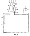
- Figure 4 is an enlarged scrap end view showing an alternative embodiment of that head;
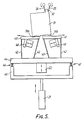
- Figure 5 is the end view of an alternative construction of an apparatus for aligning plates; and
- Figure 6 is a side view of the apparatus of Figure 5.
- Referring to Figure 1, a machine for casting straps on groups of battery plates and separators is generally indicated at 10. The machine has a
loading station 11, a brush andflux station 12, acasting station 13 and anunloading station 14.Carriers 15 for groups of plates and separators are mounted around the periphery of a table 16 and can be moved on the table successively through thestations 11 to 14. - For the apparatus, which will be described below, it is proposed that one
wall 17 should be fixed to define a datum for the sides of the plates and separators whereas theopposite wall 18 should be sprung-loaded into an outer position and mounted so that it is moveable towards the datum wall. With the wide separation thus available, the operator at theloading station 11 can pick up groups of plates and separators and load them into thecarrier 15 without being greatly concerned with their relative positions. The table 16 is then carried to the brushing andfluxing station 12 at which is located alignment apparatus 19 (see Fig. 2). - This
apparatus 19 has a table 20, which is mounted on a frame which is lifted by anhydraulic ram 21, to isolate the table from the rest of the machine, and a vertically-actinglow frequency vibrator 22. A further cyclically horizontally actingvibrator 23 is also engaged on the table. Positioned above the table and space therefrom is ahead 24, which carries pairs oflug aligning walls weight 27 and a furthersuch weight 27a depends in the centre of thehead 24. Alternatively there may be two weights adjacent the edges of the plate. Thehead 24 is mounted on aram 28 or other lifting apparatus for movement towards and away from the table 20. The apparatus also includes thecarrier 15 andram 29 which is positioned to move thewall 18 of the carrier inwardly. - In use, the
carrier 15 bringsplates 31 and interdigitedseparators 30 to thealignment apparatus 19. As has been explained above, the plates and separators have not been aligned at this stage. When thecarrier 15 arrives in the position indicated in figures 2 & 3, the table 20 moves upwardly to engage the group ofseparators 30 andplates 31, whereupon the clamp (not shown) on thecarrier 15 is released. The table 20 is vibrated by thevibrators ram 29 then urges thewall 18 inwardly to push the edges of theseparators 30 against thedatum wall 17 establishing their lateral aligned position. Immediately afterwards, thehead 24 is lowered so that theweights plates 31 andseparators 30 respectively pushing them firmly down on the table 20 establishing a vertically aligned position for both plates and separators. Thewalls upstanding lugs 32 on theplates 31 and hence drawing theplates 31 into alignment. The group is therefore aligned in all directions and it is then re-clamped by thecarrier 15 and the table 20 and head 24 move away from thecarrier 15 to allow it to rotate for the brushing and fluxing operation. - As can be seen in Figure 4, the
walls shafts inter-engaging cog wheels - Turning to Figures 5 and 6 the
support 20 is divided into twohalves leaf springs base plate 44 which is in turn mounted on asubframe 45 byanti-vibrating mountings piston 21. As before the low frequency vibrations are induced by apiston vibratory 22 which acts, in this case, on thebase plate 44. - It will be seen that the
outer leaf springs 42 are vertical in each case, butsprings 43 are each inwardly inclined. This means that when therespective support sections linear vibrators - Thus if when a
lug 32 is engaged bylug aligning walls 25, 26 (which in this construction rotate into engagement), theplate 31 tilts over to the position shown in Figure 6, itscorner 31a is dragged in a leftward direction until the foot 31b lands on the table 41. In this position theplate 31 is now standing equally on thesupports - It has been found that this high frequency vibration is an adequate substitute for the circular vibration mentioned previously as well as having the advantage of overcoming the problem of tilting plates.
- It will be understood that this split support system may be applicable in other manufacturing processes where goods can be received in a tilted condition.
- It will be seen that the invention can be used to align stacks of other elements having similar characteristics and such apparatus is included in the scope of the invention.
- The apparatus may be particularly advantageous if automatic loading of the carrier takes place, because it removes the need for accurate alignment at that stage.
- When the alternate plates are contained with in separator envelopes it may be necessary to push them into alignment against a fixed datum using lateral pressure e.g. from a movable wall.
Claims (19)
Applications Claiming Priority (4)
| Application Number | Priority Date | Filing Date | Title |
|---|---|---|---|
| GB888801468A GB8801468D0 (en) | 1988-01-22 | 1988-01-22 | Alignment apparatus |
| GB8801468 | 1988-01-22 | ||
| GB888827077A GB8827077D0 (en) | 1988-11-19 | 1988-11-19 | Alignment apparatus |
| GB8827077 | 1988-11-19 |
Publications (2)
| Publication Number | Publication Date |
|---|---|
| EP0327208A2 true EP0327208A2 (en) | 1989-08-09 |
| EP0327208A3 EP0327208A3 (en) | 1989-11-29 |
Family
ID=26293361
Family Applications (2)
| Application Number | Title | Priority Date | Filing Date |
|---|---|---|---|
| EP89901729A Expired - Lifetime EP0398921B1 (en) | 1988-01-22 | 1989-01-13 | Alignment apparatus |
| EP89300295A Pending EP0327208A3 (en) | 1988-01-22 | 1989-01-13 | Alignment apparatus |
Family Applications Before (1)
| Application Number | Title | Priority Date | Filing Date |
|---|---|---|---|
| EP89901729A Expired - Lifetime EP0398921B1 (en) | 1988-01-22 | 1989-01-13 | Alignment apparatus |
Country Status (6)
| Country | Link |
|---|---|
| US (1) | US5123160A (en) |
| EP (2) | EP0398921B1 (en) |
| JP (1) | JP2851335B2 (en) |
| DE (1) | DE68908396T2 (en) |
| ES (1) | ES2044228T3 (en) |
| WO (1) | WO1989006867A2 (en) |
Cited By (3)
| Publication number | Priority date | Publication date | Assignee | Title |
|---|---|---|---|---|
| EP0561069A1 (en) * | 1992-03-18 | 1993-09-22 | Matsushita Electric Industrial Co., Ltd. | Method of stacking and transferring lead storage battery plates and apparatus. |
| WO2001052334A1 (en) * | 2000-01-14 | 2001-07-19 | Tbs Engineering Limited | Methods and apparatus for applying a secondary closure to an assembly of a lid attached to a battery box |
| WO2020216758A1 (en) * | 2019-04-23 | 2020-10-29 | Grob-Werke Gmbh & Co. Kg | Device and method for producing a cell stack |
Families Citing this family (5)
| Publication number | Priority date | Publication date | Assignee | Title |
|---|---|---|---|---|
| US5626989A (en) * | 1994-11-22 | 1997-05-06 | Long Island Lighting Company | Quasi-solid plate storage battery |
| US5685051A (en) * | 1996-05-23 | 1997-11-11 | Eberle Engineering Co., Inc. | Method and apparatus for aligning battery lugs |
| US6092978A (en) * | 1997-03-12 | 2000-07-25 | Fishchersips, Inc. | Alignment device used to manufacture a plurality of structural insulated panels |
| KR101888211B1 (en) * | 2013-12-09 | 2018-08-13 | 주식회사 엘지화학 | An Apparatus for Aligning Stepped Battery and a Method thereof |
| JP2019200967A (en) * | 2018-05-18 | 2019-11-21 | トヨタ自動車株式会社 | Alignment device |
Family Cites Families (14)
| Publication number | Priority date | Publication date | Assignee | Title |
|---|---|---|---|---|
| US1602684A (en) * | 1923-09-14 | 1926-10-12 | Jeter M Lancaster | Bed clamp |
| US2628992A (en) * | 1949-07-20 | 1953-02-17 | Globe Union Inc | Method and apparatus for positioning battery plates for leadburning |
| US2981393A (en) * | 1951-01-16 | 1961-04-25 | George S Gunnison | Device for orienting apertured plates |
| US3052968A (en) * | 1959-12-23 | 1962-09-11 | Electric Storage Battery Co | Battery separator positioning machine |
| FR1317259A (en) * | 1960-12-30 | 1963-02-08 | Globe Union Inc | Machine for manufacturing electric storage battery cells |
| GB1252925A (en) * | 1968-02-13 | 1971-11-10 | ||
| GB1371162A (en) * | 1972-01-04 | 1974-10-23 | Tudor Ab | Apparatus for the preparation of electrode sets |
| US3808663A (en) * | 1972-09-11 | 1974-05-07 | Wirtz Mfg Co | Aligning mechanism for battery grid casting machine |
| US4168772A (en) * | 1974-10-01 | 1979-09-25 | General Battery Corporation | Apparatus and method for stacking battery plates and separators |
| DE2526159C3 (en) * | 1975-06-12 | 1978-10-05 | Accumulatorenwerk Hoppecke Carl Zoellner & Sohn, 5000 Koeln | Device for aligning the accumulator plates and separators of accumulators |
| US4349959A (en) * | 1980-04-14 | 1982-09-21 | General Battery Corporation | Apparatus for aligning battery plates and separators |
| JPS5788677A (en) * | 1980-11-20 | 1982-06-02 | Yuasa Battery Co Ltd | Manufacture of storage battery and its device |
| US4415149A (en) * | 1981-06-25 | 1983-11-15 | Wen Products, Inc. | Portable workbench |
| US4583286A (en) * | 1983-03-28 | 1986-04-22 | Gnb Batteries Inc. | Apparatus and method for processing and transferring battery cell elements |
-
1989
- 1989-01-13 ES ES89901729T patent/ES2044228T3/en not_active Expired - Lifetime
- 1989-01-13 JP JP1501534A patent/JP2851335B2/en not_active Expired - Lifetime
- 1989-01-13 WO PCT/GB1989/000027 patent/WO1989006867A2/en not_active Ceased
- 1989-01-13 EP EP89901729A patent/EP0398921B1/en not_active Expired - Lifetime
- 1989-01-13 EP EP89300295A patent/EP0327208A3/en active Pending
- 1989-01-13 DE DE89901729T patent/DE68908396T2/en not_active Expired - Lifetime
-
1990
- 1990-06-28 US US07/536,590 patent/US5123160A/en not_active Expired - Lifetime
Cited By (8)
| Publication number | Priority date | Publication date | Assignee | Title |
|---|---|---|---|---|
| US5431530A (en) * | 1992-03-13 | 1995-07-11 | Matsushita Electric Industrial Co., Ltd. | Apparatus for transferring and stocking lead plates for storage batteries |
| EP0561069A1 (en) * | 1992-03-18 | 1993-09-22 | Matsushita Electric Industrial Co., Ltd. | Method of stacking and transferring lead storage battery plates and apparatus. |
| WO2001052334A1 (en) * | 2000-01-14 | 2001-07-19 | Tbs Engineering Limited | Methods and apparatus for applying a secondary closure to an assembly of a lid attached to a battery box |
| US6841035B2 (en) | 2000-01-14 | 2005-01-11 | Tbs Engineering Limited | Methods and apparatus for applying a secondary closure to an assembly of a lid attached to a battery box |
| KR100745288B1 (en) * | 2000-01-14 | 2007-08-01 | 티비에스 엔지니어링 리미티드 | Apparatus and method for mounting a secondary closure to a lid assembly attached to a battery box |
| WO2020216758A1 (en) * | 2019-04-23 | 2020-10-29 | Grob-Werke Gmbh & Co. Kg | Device and method for producing a cell stack |
| CN113767492A (en) * | 2019-04-23 | 2021-12-07 | 格鲁博-工厂有限及两合公司 | Apparatus and method for making battery stacks |
| US11984550B2 (en) | 2019-04-23 | 2024-05-14 | Grob-Werke Gmbh & Co. Kg | Device and method for manufacturing a cell stack |
Also Published As
| Publication number | Publication date |
|---|---|
| ES2044228T3 (en) | 1994-01-01 |
| EP0327208A3 (en) | 1989-11-29 |
| EP0398921B1 (en) | 1993-08-11 |
| DE68908396T2 (en) | 1994-03-10 |
| US5123160A (en) | 1992-06-23 |
| EP0398921A1 (en) | 1990-11-28 |
| JP2851335B2 (en) | 1999-01-27 |
| WO1989006867A3 (en) | 1989-08-24 |
| WO1989006867A2 (en) | 1989-07-27 |
| JPH03503329A (en) | 1991-07-25 |
| DE68908396D1 (en) | 1993-09-16 |
Similar Documents
| Publication | Publication Date | Title |
|---|---|---|
| US5123160A (en) | Alignment apparatus | |
| KR20060049419A (en) | How to load and cut glass plates on a cutting table | |
| KR20160107570A (en) | Apparatus for aligning secondary battery cell | |
| CN220681261U (en) | Material receiving box of cutting machine and feeding structure of cutting machine | |
| EP0958631B1 (en) | Frame and loading apparatus for groups of battery plates | |
| CN114873289A (en) | Disk feeding device | |
| CN120622122B (en) | An automatic cylinder palletizing line | |
| CA1159106A (en) | Apparatus for aligning battery plates and separators | |
| AU622144B2 (en) | Alignment apparatus | |
| CN217624359U (en) | Automatic case packer for bottle caps | |
| US20060104803A1 (en) | Method and device for exchanging transport elements | |
| CN213976045U (en) | Single iron core pickup device | |
| JPH05155428A (en) | Device to condense accumulated body of members cut by dies, and correct locations of them at the same time | |
| SE459223B (en) | DEVICE FOR THE RECOVERY OF PREFERENCES Frozen in molds | |
| CN216425958U (en) | Automatic feeding and discharging machine of axle broaching robot | |
| CN217478532U (en) | Double-station high-speed stacking robot | |
| CN215100712U (en) | Laser cutting balance machine tray goes up unloading subassembly | |
| JP2005190748A (en) | Inserting method of electrode group for storage battery into container | |
| JP3333632B2 (en) | Work loading / unloading device with product accumulation device | |
| CN222856042U (en) | Cylindrical lithium ion battery vibrating device | |
| CN223441380U (en) | Mechanical equipment for handling product combinations | |
| CN223643006U (en) | Product tray for storing a processed product of a split-type processing of a plate-shaped workpiece and machine with such a product tray | |
| CN114313789B (en) | Empty disc transfer device | |
| JP2005197103A (en) | Insertion method of electrode group for battery into battery case | |
| CN217349295U (en) | Stereoscopic warehouse conveyer pile up neatly mechanism |
Legal Events
| Date | Code | Title | Description |
|---|---|---|---|
| PUAI | Public reference made under article 153(3) epc to a published international application that has entered the european phase |
Free format text: ORIGINAL CODE: 0009012 |
|
| AK | Designated contracting states |
Kind code of ref document: A2 Designated state(s): ES |
|
| PUAL | Search report despatched |
Free format text: ORIGINAL CODE: 0009013 |
|
| AK | Designated contracting states |
Kind code of ref document: A3 Designated state(s): ES |
|
| 17P | Request for examination filed |
Effective date: 19900423 |
|
| STAA | Information on the status of an ep patent application or granted ep patent |
Free format text: STATUS: EXAMINATION IS IN PROGRESS |
|
| 17Q | First examination report despatched |
Effective date: 19920218 |
|
| XX | Miscellaneous (additional remarks) |
Free format text: VERFAHREN ABGESCHLOSSEN INFOLGE VERBINDUNG MIT 89901729.7/0398921 (EUROPAEISCHE ANMELDENUMMER/VEROEFFENTLICHUNGSNUMMER) VOM 29.04.92. |