EP0326528A2 - Apparatus for controlling the production of paper rolls - Google Patents
Apparatus for controlling the production of paper rolls Download PDFInfo
- Publication number
- EP0326528A2 EP0326528A2 EP89830026A EP89830026A EP0326528A2 EP 0326528 A2 EP0326528 A2 EP 0326528A2 EP 89830026 A EP89830026 A EP 89830026A EP 89830026 A EP89830026 A EP 89830026A EP 0326528 A2 EP0326528 A2 EP 0326528A2
- Authority
- EP
- European Patent Office
- Prior art keywords
- presser
- diameter
- roll
- small roll
- paper
- Prior art date
- Legal status (The legal status is an assumption and is not a legal conclusion. Google has not performed a legal analysis and makes no representation as to the accuracy of the status listed.)
- Granted
Links
- 238000004519 manufacturing process Methods 0.000 title description 6
- 238000004804 winding Methods 0.000 claims abstract description 5
- 238000005303 weighing Methods 0.000 claims description 5
- 238000006073 displacement reaction Methods 0.000 claims description 3
- 238000003825 pressing Methods 0.000 claims description 2
- 230000015572 biosynthetic process Effects 0.000 claims 1
- 238000013459 approach Methods 0.000 abstract 1
- 238000012937 correction Methods 0.000 description 19
- 238000012216 screening Methods 0.000 description 5
- 238000005520 cutting process Methods 0.000 description 4
- 238000010586 diagram Methods 0.000 description 4
- 230000003287 optical effect Effects 0.000 description 4
- 230000003247 decreasing effect Effects 0.000 description 2
- 238000004806 packaging method and process Methods 0.000 description 2
- 238000002360 preparation method Methods 0.000 description 2
- 238000009825 accumulation Methods 0.000 description 1
- 238000005056 compaction Methods 0.000 description 1
- 230000001419 dependent effect Effects 0.000 description 1
- 238000000034 method Methods 0.000 description 1
Images

Classifications
-
- B—PERFORMING OPERATIONS; TRANSPORTING
- B65—CONVEYING; PACKING; STORING; HANDLING THIN OR FILAMENTARY MATERIAL
- B65H—HANDLING THIN OR FILAMENTARY MATERIAL, e.g. SHEETS, WEBS, CABLES
- B65H18/00—Winding webs
- B65H18/08—Web-winding mechanisms
- B65H18/14—Mechanisms in which power is applied to web roll, e.g. to effect continuous advancement of web
- B65H18/20—Mechanisms in which power is applied to web roll, e.g. to effect continuous advancement of web the web roll being supported on two parallel rollers at least one of which is driven
-
- B—PERFORMING OPERATIONS; TRANSPORTING
- B65—CONVEYING; PACKING; STORING; HANDLING THIN OR FILAMENTARY MATERIAL
- B65H—HANDLING THIN OR FILAMENTARY MATERIAL, e.g. SHEETS, WEBS, CABLES
- B65H18/00—Winding webs
- B65H18/08—Web-winding mechanisms
- B65H18/26—Mechanisms for controlling contact pressure on winding-web package, e.g. for regulating the quantity of air between web layers
-
- B—PERFORMING OPERATIONS; TRANSPORTING
- B65—CONVEYING; PACKING; STORING; HANDLING THIN OR FILAMENTARY MATERIAL
- B65H—HANDLING THIN OR FILAMENTARY MATERIAL, e.g. SHEETS, WEBS, CABLES
- B65H26/00—Warning or safety devices, e.g. automatic fault detectors, stop-motions, for web-advancing mechanisms
- B65H26/06—Warning or safety devices, e.g. automatic fault detectors, stop-motions, for web-advancing mechanisms responsive to predetermined lengths of webs
-
- B—PERFORMING OPERATIONS; TRANSPORTING
- B65—CONVEYING; PACKING; STORING; HANDLING THIN OR FILAMENTARY MATERIAL
- B65H—HANDLING THIN OR FILAMENTARY MATERIAL, e.g. SHEETS, WEBS, CABLES
- B65H26/00—Warning or safety devices, e.g. automatic fault detectors, stop-motions, for web-advancing mechanisms
- B65H26/08—Warning or safety devices, e.g. automatic fault detectors, stop-motions, for web-advancing mechanisms responsive to a predetermined diameter
-
- B—PERFORMING OPERATIONS; TRANSPORTING
- B65—CONVEYING; PACKING; STORING; HANDLING THIN OR FILAMENTARY MATERIAL
- B65H—HANDLING THIN OR FILAMENTARY MATERIAL, e.g. SHEETS, WEBS, CABLES
- B65H2408/00—Specific machines
- B65H2408/20—Specific machines for handling web(s)
- B65H2408/23—Winding machines
- B65H2408/235—Cradles
-
- B—PERFORMING OPERATIONS; TRANSPORTING
- B65—CONVEYING; PACKING; STORING; HANDLING THIN OR FILAMENTARY MATERIAL
- B65H—HANDLING THIN OR FILAMENTARY MATERIAL, e.g. SHEETS, WEBS, CABLES
- B65H2511/00—Dimensions; Position; Numbers; Identification; Occurrences
- B65H2511/10—Size; Dimensions
- B65H2511/11—Length
Definitions
- the core on which the paper is wound may also vary in diameter, and this creates a further problem for the manufacturer in keeping the outside diameter of the finished roll within pre-determined limits.
- the apparatus of the present invention provides such equipment.
- the apparatus comprises means for detecting the desired diameter, means for detecting the weight of a finished roll and/or of the length of paper wound at any moment, means for pre-setting the final diameter to be reached, as well as means for comparing the pre-set data with the detected ones, and correction means to keep length and diameter or weight and diameter steady.
- the invention relates to machines for paper manufacture and, in particular, to the rewinders, i.e., machines which are fed with one or more large rolls or with a roll of two-ply paper, for the production of "logs” or rolls of paper having relatively smaller diameter. These "logs” are subsequently cut perpendicularly to their axes to provide small rolls of paper for use as toilet paper, kitchen towels, or for similar uses.
- it is suitable and sometimes indispensable to provide an exact diameter of the roll so that the small rolls meet requirements of successive operations, such as cutting and packaging, as well as practical requirements, such as fitting into a toilet-roll dispenser.
- the exact diameter be obtained with a precise and pre-determined length of paper, or with a precise and pre-determined number of sheets (when the paper is perforated to be detached in sheets of equal length), again for commercial requirements and so as not to exceed desired paper length according to economical requirements.
- a particular requirement is that of keeping the length (that is, the number of sheets of the paper) or the weight of the small roll, and the diameter of the small rolls uniform, even though the characteristics (such as basis weight or caliper or surface finish) may not be constant.
- the apparatus in question ensures control and correction of the production in order to achieve uniformity of the above-mentioned cahracteristics.
- the correction means may comprise a regulator for adjusting the pressure, i.e., the thrust exerted by a small presser acting on the surface of the roll being formed.
- the diameter-sensing means may be associated with the small presser, and it is activated when the desired diameter is reached.
- the apparatus may be combined with an electronic logic able to operate a correction by means of the small presser acting on the roll being formed and activated by the thrust exerted by said roll on the presser.
- the apparatus may comprise at least two sensors and a cam member, or an encoder, for evaluating limit positions, and thresholds for controlling fine and coarse adjustments according to the sensed diameter of the stick, i.e., according to the position of the presser assembly.
- the diameter sensor may be arranged as an encoder that measures the angular displacement of the presser arm.
- a weighing means may be provided, such as a load cell, able to evaluate the weight of the log or roll as data to be used for corrections.
- the apparatus provides for carrying out the simultaneous control of the diameter and length of the paper or of the weight of the log up to the pre-determined limit. Moreover, the apparatus provides for keeping said diameter exact when the characteristics of paper are changing, either by imposing a change of length of the paper supplied for each roll, or by keeping the length and the diameter steady through a variation of the thrust operated by the small presser.
- the presser thrust is reduced, thus increasing the roll diameter with the same length of wound paper.
- paper may be added to the roll, in order to reach the desired length, by causing a greater thrusting action of the presser on the roll, to reach the pre-set diameter with a greater quantity of rolled-up paper.
- the apparatus allows the paper weight to be kept steady through a variation of the length, and by maintaining the diameter steady through a variation of the presser thrust on the roll being formed.
- All the operations can be carried out with the machine in operation, without interrupting the production process, and providing for successive corrections up to the restoration of the pre-set and desired limits.
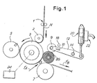
- the continuously fed paper web N is transversally perforated at equal distances (to provide sheets) by a device 1 and is turned by a cylinder 2 in order to be fed to the main cylinder 3.
- Cylinder 3 determines the total length of web to be wound and includes a cutting device, including a cylinder 5, which carries out the cutting of said web N.
- Number 7 indicates a cylinder which cooperates with cylinder 3 and defines an interspace with it, wherein a tubular core, preferably made of cardboard, is inserted--in a known manner--in the direction of arrow fA.
- the paper web is wound on the core to form the roll or log BS, which is then suitably moved away in the direction of arrow fB.
- Such cutting and winding arrangements are well-known, as shown in U.S. Patent 4,327,877. They may include also a so-called presser, i.e., a further pressing roller indicated by 9, which is movably mounted, for example, on a pair of arms 12 pivoted at 14. Presser 9 is able to produce a suitable pressure, that is, a thrust on the roll BS being formed and thus to completely define the diameter of the roll.
- Presser 9 is capable of varying the pressure exerted on the roll BS being formed and thereby compact the paper in the roll to a more or less degree.
- the presser 9 assembly, with its supporting arms 12, allows also to sense the diameter of the roll being formed and, therefore, the presser itself may cooperate with a diameter evaluating sensor.
- the regulation of the pressure exerted by the presser on the roll may be obtained by an adjustable weight slidable along arm 12, by a screw-control or other device (not shown).
- a sensor for evaluating said diameter, which sensor comprises a screen 16 located on the arms 12, and a sight 18 of optical type such as an "electric eye", for example, at a fixed position.
- a more simple arrangement includes a suitably positioned microswitch which establishes the diameter that the roll BS must reach to meet the above-mentioned requirements.
- Two optical sensors may be provided that can regulate the coarse and fine corrections of the presser thrust on the paper.
- the regulator may consist of a cylinder piston system 20 supplied by pressure adjustable through a control system, generally indicated by 22, which is dependent on control means electronically operated according to a suitable program.
- the regulator may operate by increase of the pressure inside the system 20 and thus reduce the presser thrust on the roll, and vice versa.
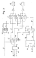
- Fig.2 shows an electronic block diagram including an input 31 for the data concerning the desired diameter, which data are obtained by a sensor like that indicated by 16,18 in Fig. 1.
- Numerals 33 and 35 in Fig.2 indicate two timers which are set for a longer and shorter time, respectively, to obtain coarse and fine corrections, respectively.
- Numerals 36 and 37 indicate the date input for setting the lengths (i.e., the meters) of paper representing the limits of the allowable range of paper, while numeral 38 indicates the input of the actual value of the length of the fed paper, such input being supplied through a counter 24 associated with cylinder 3.
- Numeral 39 indicates an electronic logic which can receive a card (which can be easily changed) containing the program.
- Numerals 41, 43, and 45 indicate three gates associated with the three outputs of electronic logic 39 and which receive also the data relevant to the reached diameter from input 31. Gates 41 and 43 are intended for the coarse correction and gate 45 for the fine correction.
- switches 51 and 53 From gates 41 and 43 data are fed through lines 47 and 49 to two switches 51 and 53, respectively, for increasing or decreasing coarse correction represented by blocks 55 and 57 respectively.
- Switches 51 and 53 receive the correction time from timer 33 which is set for a longer duration.
- the two corrections 55 and 57 may also be activated by switches 59 and 61, provided for the fine adjustment, which are connected to timer 35, set for the shorter duration, and by gates 67 and 69.
- the correcting signals arrive at switches 59 and 61 via two lines 63 and 65, respectively, coming from two gates 67 and 69 fed with data obtained via line 71 from the gate 45 of the electronic logic.
- Data for the delivery of the type of fine correction to be made are obtained from lines 73 and 75 which are connected to the counter 24 for detecting the length of passed paper, said counter being connected, for example, to cylinder 3 and to the diameter sensor such as that indicated by 16 and 18.
- the operation of the apparatus is as follows.
- the optical sensor (or microswitch) 16, 18 - either single or dual- is activated because the roll diameter has reached the desired preset value, and the counter 24, which provides the information relative to the length of wound paper, has not arrived at any of the two selections preset by 36 and 37 in the electronic logic, it is necessary to increase the length of paper and thus the pressure of presser 9 must be increased so that greater compaction of the rolls of paper will allow an accumulation of a larger amount of paper while maintaining the roll diameter at the desired value.
- microswitch 16, 18 is actuated and the counter 24 has already reached the upper selection limit for the allowable paper length, this means that there is sufficient paper in the roll, and as a consequence the pressure of presser 9 must be lowered so that the desired diameter is reached with a smaller amount of paper.
- Figs. 3 and 4 show a modified embodiment, in which two proximity or optical sensors 118 and 120 can cooperate with a screening body 116 carried by arm 12.
- Sensors 118 and 120 may be carried by a support 122 pivotable at 114.
- arm 12 is pivotable at 114.
- Support 122 is adjustable, for example, by a screw 126 to set the position of the two sensors 118 and 120 and thus the desired diameter for roll BS.
- the distance between the two sensors 118 and 120 can also be adjusted for establishing the tolerance of the diameter of roll BS.
- the regulation system is driven by a series of pulses.
- lines 201, 202, 203 and 204 may be considered as the thresholds delimited by pulses obtained from the pair of sensors 118 and 120 influenced by screen 116, wherein: - 201 corresponds to the screening (actuating) pulse of the first sensor; - 202 corresponds to the releasing (abandoning) pulse of the first sensor; - 203 corresponds to the screening (actuating) pulse of the second sensor; and - 203 corresponds to the releasing (abandoning) pulse of the second sensor.
- the regulation may be carried out by comparing the output of counter 24 driven by the main cylinder 3 (proportional to the length of wound paper) with pulses 201, 202, 203 and 204 through the following logical consequences:
- Another solution can be that of mounting a pulse genertor on the fulcrum 14 of arm 12 of presser 9 and comparing the pulses thereof with those emitted by the counter 24 on cylinder 3 with the same criteria as those of the preceding solution.
- the programmer compares the length of paper passed through - evaluated by pulses produced by the counter 24 on cylinder 3 - with the preset length (which takes into account a constant which is necessary to carry out the whole exchange cycle) and, if the two values are substantially equal, the change of rolls (an operation which always takes place in any case) is actually carried out without making a change in the presser thrust. If, instead, the two values are different (being either greater or smaller) the system will initiate a change by decreasing or increasing the thrust of the presser in order to correct the amount of paper in the roll. The greater the difference between the two countings (paper length and diameter of roll BS), the greater will be this correction.
- the diameter and weight of the roll may be preset and the corrections performed by imposing variations in the length of paper.
- the diameter of the roll is ensured but not the length of the wound paper, which length may vary by an amount of even one revolution of cylinder 3.
- Weighing systems may be included, such as load cells like those shown in dotted lines at C in Fig. 3 for weighing the roll which has left the position BS (where it was formed) and has moved along chute S in the direction of arrow fB. By the weight date it is possible to affect the corrections of the presser thrust and/or of the length of the paper which has been fed to each roll.
Landscapes
- Controlling Rewinding, Feeding, Winding, Or Abnormalities Of Webs (AREA)
- Paper (AREA)
- Replacement Of Web Rolls (AREA)
Abstract
Description
- In the preparation of logs or rolls of paper of relatively small diameter from large diameter rolls produced on a paper-making machine, the equipment and apparatus have been well developed to produce such logs or rolls automatically and at high speed.
- Relevant patents relating to the background of this type of paper-converting machinery and process are the U.S. Patents 3,869,095, 4,327,877 and 4,422588.
- In the preparation of these logs or rolls, the web of paper fed to the machine quite often varies in basis weight, caliper, surface characteristics and the like, and it is also important that the manufacturer provide the precise number of sheets or usable units in each of the finished rolls.
- All of this has to be accomplished while keeping the outside diameter of the roll within pre-determined limits, which are generally dictated by the wrapping and packaging equipment, as well as by the size of the holder or dispenser on which the finished roll is used by the consumer.
- The core on which the paper is wound may also vary in diameter, and this creates a further problem for the manufacturer in keeping the outside diameter of the finished roll within pre-determined limits.
- Under the circumstances, it is important for economic and commercial reasons that the length of the paper wound into the roll, the number of sheets or usable units provided in the roll, and the outside diameter of the roll, be controlled as accurately as possible. The apparatus of the present invention provides such equipment.
- The apparatus comprises means for detecting the desired diameter, means for detecting the weight of a finished roll and/or of the length of paper wound at any moment, means for pre-setting the final diameter to be reached, as well as means for comparing the pre-set data with the detected ones, and correction means to keep length and diameter or weight and diameter steady.
- The invention relates to machines for paper manufacture and, in particular, to the rewinders, i.e., machines which are fed with one or more large rolls or with a roll of two-ply paper, for the production of "logs" or rolls of paper having relatively smaller diameter. These "logs" are subsequently cut perpendicularly to their axes to provide small rolls of paper for use as toilet paper, kitchen towels, or for similar uses. In these machines, it is suitable and sometimes indispensable to provide an exact diameter of the roll so that the small rolls meet requirements of successive operations, such as cutting and packaging, as well as practical requirements, such as fitting into a toilet-roll dispenser.
- It is also suitable (or even necessary) that the exact diameter be obtained with a precise and pre-determined length of paper, or with a precise and pre-determined number of sheets (when the paper is perforated to be detached in sheets of equal length), again for commercial requirements and so as not to exceed desired paper length according to economical requirements.
- A particular requirement is that of keeping the length (that is, the number of sheets of the paper) or the weight of the small roll, and the diameter of the small rolls uniform, even though the characteristics (such as basis weight or caliper or surface finish) may not be constant.
- The apparatus in question ensures control and correction of the production in order to achieve uniformity of the above-mentioned cahracteristics.
- Therefore, it is an object to provide an apparatus for controlling the production of rolls or "logs" of paper produced by a rewinder fed with large rolls or two-ply paper rolls, especially for ensuring an exact overall diameter and the paper length and/or paper weight within pre-set limits. it includes means for detecting the desired diameter, means for detecting the weight of a finished roll and/or the length of paper wound into the roll, means for pre-setting the final diameter to be reached, means for comparing the pre-set data with the detected ones, and correction means.
- Advantageously, the correction means may comprise a regulator for adjusting the pressure, i.e., the thrust exerted by a small presser acting on the surface of the roll being formed.
- The diameter-sensing means may be associated with the small presser, and it is activated when the desired diameter is reached.
- The apparatus may be combined with an electronic logic able to operate a correction by means of the small presser acting on the roll being formed and activated by the thrust exerted by said roll on the presser.
- The apparatus may comprise at least two sensors and a cam member, or an encoder, for evaluating limit positions, and thresholds for controlling fine and coarse adjustments according to the sensed diameter of the stick, i.e., according to the position of the presser assembly. There can be provided two fixed sensors, which have adjustable position and interspace, and a screen member located on an arm for the angular displacement of the presser, in order to obtain the various adjustments through four practicable and subsequent pulses. Alternatively, the diameter sensor may be arranged as an encoder that measures the angular displacement of the presser arm.
- According to another embodiment,a weighing means may be provided, such as a load cell, able to evaluate the weight of the log or roll as data to be used for corrections.
- Therefore, the apparatus provides for carrying out the simultaneous control of the diameter and length of the paper or of the weight of the log up to the pre-determined limit. Moreover, the apparatus provides for keeping said diameter exact when the characteristics of paper are changing, either by imposing a change of length of the paper supplied for each roll, or by keeping the length and the diameter steady through a variation of the thrust operated by the small presser.
- In one embodiment, the presser thrust is reduced, thus increasing the roll diameter with the same length of wound paper. Vice-versa, paper may be added to the roll, in order to reach the desired length, by causing a greater thrusting action of the presser on the roll, to reach the pre-set diameter with a greater quantity of rolled-up paper.
- In a further embodiment, the apparatus allows the paper weight to be kept steady through a variation of the length, and by maintaining the diameter steady through a variation of the presser thrust on the roll being formed.
- All the operations can be carried out with the machine in operation, without interrupting the production process, and providing for successive corrections up to the restoration of the pre-set and desired limits.
- With the above and other objects in view, more information and a better understanding of the present invention may be achieved by reference to the following detailed description, while advantageous features of the invention are set out in the claims.
- For the purpose of illustrating the invention, there is shown in the accompanying drawings a form thereof which is at present preferred, although it is to be understood that the several instrumentalities of which the invention consists can be variously arranged and organized and that the invention is not limited to the precise arrangements and organizations of the instrumentalities as herein shown and described.
- In the drawings, wherein like reference characters indicate like parts:
- FIG. 1 shows a schematic representation of a rewinder, limited to the main members for the winding of the paper web into a roll.
- FIG. 2 shows a block diagram of the electronic parts relvant to the connection system.
- FIG. 3 shows another embodiment similar to FIG. 1.
- FIG. 4 shows an explanatory switching diagram.
- Referring to the attached drawings, and particularly FIGS. 1 and 3, the continuously fed paper web N is transversally perforated at equal distances (to provide sheets) by a
device 1 and is turned by acylinder 2 in order to be fed to themain cylinder 3.Cylinder 3 determines the total length of web to be wound and includes a cutting device, including acylinder 5, which carries out the cutting of said web N. -
Number 7 indicates a cylinder which cooperates withcylinder 3 and defines an interspace with it, wherein a tubular core, preferably made of cardboard, is inserted--in a known manner--in the direction of arrow fA. The paper web is wound on the core to form the roll or log BS, which is then suitably moved away in the direction of arrow fB. Such cutting and winding arrangements are well-known, as shown in U.S. Patent 4,327,877. They may include also a so-called presser, i.e., a further pressing roller indicated by 9, which is movably mounted, for example, on a pair ofarms 12 pivoted at 14.Presser 9 is able to produce a suitable pressure, that is, a thrust on the roll BS being formed and thus to completely define the diameter of the roll. -
Presser 9 is capable of varying the pressure exerted on the roll BS being formed and thereby compact the paper in the roll to a more or less degree. The presser 9 assembly, with its supportingarms 12, allows also to sense the diameter of the roll being formed and, therefore, the presser itself may cooperate with a diameter evaluating sensor. For example, the regulation of the pressure exerted by the presser on the roll may be obtained by an adjustable weight slidable alongarm 12, by a screw-control or other device (not shown). - As shown in FIG. 1, a sensor is provided for evaluating said diameter, which sensor comprises a
screen 16 located on thearms 12, and asight 18 of optical type such as an "electric eye", for example, at a fixed position. A more simple arrangement includes a suitably positioned microswitch which establishes the diameter that the roll BS must reach to meet the above-mentioned requirements. Two optical sensors may be provided that can regulate the coarse and fine corrections of the presser thrust on the paper. - On the assembly of
arms 12 ofpresser 9, means is provided for adjusting the pressure to be exerted by presser 9 on the roll BS being formed. The regulator may consist of acylinder piston system 20 supplied by pressure adjustable through a control system, generally indicated by 22, which is dependent on control means electronically operated according to a suitable program. The regulator may operate by increase of the pressure inside thesystem 20 and thus reduce the presser thrust on the roll, and vice versa. - Fig.2 shows an electronic block diagram including an
input 31 for the data concerning the desired diameter, which data are obtained by a sensor like that indicated by 16,18 in Fig. 1.Numerals Numerals numeral 38 indicates the input of the actual value of the length of the fed paper, such input being supplied through acounter 24 associated withcylinder 3.Numeral 39 indicates an electronic logic which can receive a card (which can be easily changed) containing the program.Numerals electronic logic 39 and which receive also the data relevant to the reached diameter frominput 31. Gates 41 and 43 are intended for the coarse correction andgate 45 for the fine correction. - From
gates lines switches blocks Switches timer 33 which is set for a longer duration. The twocorrections switches timer 35, set for the shorter duration, and bygates switches lines gates line 71 from thegate 45 of the electronic logic. Data for the delivery of the type of fine correction to be made are obtained fromlines counter 24 for detecting the length of passed paper, said counter being connected, for example, tocylinder 3 and to the diameter sensor such as that indicated by 16 and 18. - The operation of the apparatus is as follows.
- As the optical sensor (or microswitch) 16, 18 - either single or dual- is activated because the roll diameter has reached the desired preset value, and the
counter 24, which provides the information relative to the length of wound paper, has not arrived at any of the two selections preset by 36 and 37 in the electronic logic, it is necessary to increase the length of paper and thus the pressure ofpresser 9 must be increased so that greater compaction of the rolls of paper will allow an accumulation of a larger amount of paper while maintaining the roll diameter at the desired value. - If the
microswitch counter 24 has already reached the upper selection limit for the allowable paper length, this means that there is sufficient paper in the roll, and as a consequence the pressure ofpresser 9 must be lowered so that the desired diameter is reached with a smaller amount of paper. - The two above-mentioned corrections are achieved through
timer 33 and the enabling controls onswitches gates - Figs. 3 and 4 show a modified embodiment, in which two proximity or
optical sensors screening body 116 carried byarm 12.Sensors arm 12 is pivotable at 114. Support 122 is adjustable, for example, by a screw 126 to set the position of the twosensors sensors - In this embodiment, the regulation system is driven by a series of pulses. With reference to the diagram of Fig. 4,
lines sensors screen 116, wherein:
- 201 corresponds to the screening (actuating) pulse of the first sensor;
- 202 corresponds to the releasing (abandoning) pulse of the first sensor;
- 203 corresponds to the screening (actuating) pulse of the second sensor; and
- 203 corresponds to the releasing (abandoning) pulse of the second sensor. - The regulation may be carried out by comparing the output of
counter 24 driven by the main cylinder 3 (proportional to the length of wound paper) withpulses - (1) If the preset counting goes off and pulse 201 has not yet arrived, it is necessary to provide a coarse regulation to lower the presser thrust and slacken the winding in order quickly to increase the diameter of roll BS;
- (2) If the preset counting goes off and pulse 201 has already arrived, it is necessary to provide a fine regulation to lower the presser thrust;
- (3) If the preset counting goes off when pulse 201 has already been delivered and
pulse 202 has not, it is necessary to provide a fine regulation in order to increase the presser thrust; - (4) The
moment pulse 202 goes off and up to the moment thepulse 203 goes off, the diameter is within the tolerance range; - (5) If the preset counting goes off and
pulse 203 has already arrived, it is necessary to provide a fine regulation in order to increase the presser thrust; - (6) In the interval between
pulses - (7) If the preset counting goes off and
pulse 204 has already arrived, it is necessary to provide a coarse regulation in order to increase the presser thrust and reduce the diameter. - All this is accomplished by utilizing the two
proximity sensors screening body 116 carried by thepresser - Another solution can be that of mounting a pulse genertor on the
fulcrum 14 ofarm 12 ofpresser 9 and comparing the pulses thereof with those emitted by thecounter 24 oncylinder 3 with the same criteria as those of the preceding solution. - What has been described above relates to a kind of operation in which a certain length of paper is set beforehand, and diameter adjustments are imposed through variations of the thrust operated by
presser 9 on the roll being formed in order to assure that the final diameter of the rolls is at the desired value. - As soon as the
screening body 116 obscures thefirst sensor 118, a pulse takes place and the programmer compares the length of paper passed through - evaluated by pulses produced by thecounter 24 on cylinder 3 - with the preset length (which takes into account a constant which is necessary to carry out the whole exchange cycle) and, if the two values are substantially equal, the change of rolls (an operation which always takes place in any case) is actually carried out without making a change in the presser thrust. If, instead, the two values are different (being either greater or smaller) the system will initiate a change by decreasing or increasing the thrust of the presser in order to correct the amount of paper in the roll. The greater the difference between the two countings (paper length and diameter of roll BS), the greater will be this correction. - Alternatively, the diameter and weight of the roll may be preset and the corrections performed by imposing variations in the length of paper. In this case, the diameter of the roll is ensured but not the length of the wound paper, which length may vary by an amount of even one revolution of
cylinder 3. - Weighing systems may be included, such as load cells like those shown in dotted lines at C in Fig. 3 for weighing the roll which has left the position BS (where it was formed) and has moved along chute S in the direction of arrow fB. By the weight date it is possible to affect the corrections of the presser thrust and/or of the length of the paper which has been fed to each roll.
- It is furthermore to be understood that the present invention may be embodied in other specific forms without departing from the spirit or special attributes, and it is, therefore, desired that the present embodiments be considered in all respects as illustrative and, therefore, not restrictive, reference being made to the appended claims rather than to the foregoing description to indicate the scope of the invention.
Claims (12)
Applications Claiming Priority (2)
| Application Number | Priority Date | Filing Date | Title |
|---|---|---|---|
| IT09318/88A IT1222185B (en) | 1988-01-29 | 1988-01-29 | CONVENTION TO CONTROL THE PRODUCTION OF PAPER ROLLS PRODUCED BY THE REWINDER TO ENSURE CONSTANCE OF LENGTH OF THE WRAPPED PAPER AND / OR OF THE REACHED DIAMETER |
| IT931888 | 1988-01-29 |
Publications (3)
| Publication Number | Publication Date |
|---|---|
| EP0326528A2 true EP0326528A2 (en) | 1989-08-02 |
| EP0326528A3 EP0326528A3 (en) | 1990-07-04 |
| EP0326528B1 EP0326528B1 (en) | 1994-09-28 |
Family
ID=11128367
Family Applications (1)
| Application Number | Title | Priority Date | Filing Date |
|---|---|---|---|
| EP89830026A Expired - Lifetime EP0326528B1 (en) | 1988-01-29 | 1989-01-26 | Apparatus for controlling the production of paper rolls |
Country Status (10)
| Country | Link |
|---|---|
| EP (1) | EP0326528B1 (en) |
| JP (1) | JP2809417B2 (en) |
| KR (1) | KR950001991B1 (en) |
| AT (1) | ATE112233T1 (en) |
| BR (1) | BR8900345A (en) |
| CA (1) | CA1336201C (en) |
| DE (1) | DE68918468T2 (en) |
| ES (1) | ES2060813T3 (en) |
| IL (1) | IL89081A (en) |
| IT (1) | IT1222185B (en) |
Cited By (8)
| Publication number | Priority date | Publication date | Assignee | Title |
|---|---|---|---|---|
| WO1994027901A1 (en) * | 1993-05-28 | 1994-12-08 | Htrc Automation Inc. | Method and apparatus for producing a primary roll of material, or for determining an amount of material available on a primary roll |
| US5538199A (en) * | 1993-02-15 | 1996-07-23 | Fabio Perini S.P.A. | Rewinding machine for coreless winding of a log of web material with a surface for supporting the log in the process of winding |
| US5806785A (en) * | 1993-05-28 | 1998-09-15 | Recherche D.C.B.L. Inc./D.C.B.L. Research Inc. | Method and apparatus for producing a primary roll of material or for determining an amount of material available on a primary roll |
| WO1999033008A3 (en) * | 1997-12-23 | 1999-11-11 | Kimberly Clark Co | System and method for collecting data on product consumption |
| EP1094021A1 (en) * | 1999-10-18 | 2001-04-25 | Giovanni Gambini | Device for controlling winding of a log in a re-reeling machine |
| US6411920B1 (en) | 1999-06-23 | 2002-06-25 | Kimberly-Clark Worldwide, Inc. | System and method for collecting data on product consumption |
| CN109969833A (en) * | 2017-12-28 | 2019-07-05 | 红塔烟草(集团)有限责任公司 | Cigarette packer reel capsule paper exhausts automatic change of lap splicing apparatus |
| CN110550484A (en) * | 2019-09-20 | 2019-12-10 | 杜军旗 | Multifunctional paper breaking mechanism of coreless and cored rewinder and paper breaking method thereof |
Families Citing this family (9)
| Publication number | Priority date | Publication date | Assignee | Title |
|---|---|---|---|---|
| US5190232A (en) * | 1990-11-13 | 1993-03-02 | E. I. Du Pont De Nemours And Company | Wind-up lay-on-roll apparatus |
| ITFI20030009A1 (en) * | 2003-01-15 | 2004-07-16 | Perini Fabio Spa | REWINDING MACHINE AND METHOD FOR THE PRODUCTION OF ROLLS, WITH MEANS FOR THE CONTROL OF THE FINAL DIAMETER OF THE ROLLS |
| US7783380B2 (en) | 2003-12-31 | 2010-08-24 | Kimberly-Clark Worldwide, Inc. | System and method for measuring, monitoring and controlling washroom dispensers and products |
| US7774096B2 (en) | 2003-12-31 | 2010-08-10 | Kimberly-Clark Worldwide, Inc. | Apparatus for dispensing and identifying product in washrooms |
| WO2008150608A2 (en) * | 2007-05-04 | 2008-12-11 | Stexley-Brake, Llc | Shipping and packing tape dispenser and mount |
| KR100908953B1 (en) * | 2007-10-24 | 2009-07-22 | 노경일 | Nonwoven fabric processing apparatus and method |
| US9809417B2 (en) | 2015-08-14 | 2017-11-07 | The Procter & Gamble Company | Surface winder |
| KR101635789B1 (en) * | 2016-01-21 | 2016-07-20 | 주식회사 한진 | Automatic packing device |
| IT201800006604A1 (en) * | 2018-06-25 | 2019-12-25 | Rewinding machine for the production of logs of paper material. |
Citations (6)
| Publication number | Priority date | Publication date | Assignee | Title |
|---|---|---|---|---|
| GB2087362A (en) * | 1980-11-14 | 1982-05-26 | Masson Scott Thrissell Eng Ltd | Winding web at constant winding density |
| JPS58130853A (en) * | 1982-01-29 | 1983-08-04 | Fujitsu Ltd | Detection mechanism of medium near end |
| JPS59143837A (en) * | 1983-02-07 | 1984-08-17 | Fuji Tekkosho:Kk | Winding control for web and its device |
| JPS60223761A (en) * | 1984-04-18 | 1985-11-08 | Oki Electric Ind Co Ltd | Paper feeding mechanism for rolled type recording paper |
| JPS6181352A (en) * | 1984-09-25 | 1986-04-24 | Ricoh Co Ltd | Curing device for curling propensity |
| GB2189907A (en) * | 1986-04-29 | 1987-11-04 | Jagenberg Ag | Control of web winding |
Family Cites Families (3)
| Publication number | Priority date | Publication date | Assignee | Title |
|---|---|---|---|---|
| JPS5742912Y2 (en) * | 1979-07-18 | 1982-09-21 | ||
| JPS597650A (en) * | 1982-07-07 | 1984-01-14 | Toshiba Corp | Winding tightness control device |
| JPS63180666A (en) * | 1987-01-22 | 1988-07-25 | Toshiba Corp | Taking-up stiffness controller |
-
1988
- 1988-01-29 IT IT09318/88A patent/IT1222185B/en active
-
1989
- 1989-01-25 JP JP1014231A patent/JP2809417B2/en not_active Expired - Lifetime
- 1989-01-26 IL IL8908189A patent/IL89081A/en not_active IP Right Cessation
- 1989-01-26 DE DE68918468T patent/DE68918468T2/en not_active Expired - Fee Related
- 1989-01-26 KR KR1019890000826A patent/KR950001991B1/en not_active IP Right Cessation
- 1989-01-26 ES ES89830026T patent/ES2060813T3/en not_active Expired - Lifetime
- 1989-01-26 EP EP89830026A patent/EP0326528B1/en not_active Expired - Lifetime
- 1989-01-26 AT AT89830026T patent/ATE112233T1/en not_active IP Right Cessation
- 1989-01-27 BR BR898900345A patent/BR8900345A/en not_active IP Right Cessation
- 1989-01-30 CA CA000589529A patent/CA1336201C/en not_active Expired - Fee Related
Patent Citations (6)
| Publication number | Priority date | Publication date | Assignee | Title |
|---|---|---|---|---|
| GB2087362A (en) * | 1980-11-14 | 1982-05-26 | Masson Scott Thrissell Eng Ltd | Winding web at constant winding density |
| JPS58130853A (en) * | 1982-01-29 | 1983-08-04 | Fujitsu Ltd | Detection mechanism of medium near end |
| JPS59143837A (en) * | 1983-02-07 | 1984-08-17 | Fuji Tekkosho:Kk | Winding control for web and its device |
| JPS60223761A (en) * | 1984-04-18 | 1985-11-08 | Oki Electric Ind Co Ltd | Paper feeding mechanism for rolled type recording paper |
| JPS6181352A (en) * | 1984-09-25 | 1986-04-24 | Ricoh Co Ltd | Curing device for curling propensity |
| GB2189907A (en) * | 1986-04-29 | 1987-11-04 | Jagenberg Ag | Control of web winding |
Non-Patent Citations (4)
| Title |
|---|
| PATENT ABSTRACTS OF JAPAN vol. 10, no. 253 (M-512)(2309) 29 August 1986; & JP-A-61 081 352 (RICOH CO LTD) 24 April 1986 * |
| PATENT ABSTRACTS OF JAPAN vol. 10, no. 83 (M-466)(2140) 2 April 1986; & JP-A-60 223 761 (OKI DENKI KOGYO K.K.) 8 November 1985 * |
| PATENT ABSTRACTS OF JAPAN vol. 7, no. 244 (M-252)(1389) 28 October 1983; & JP-A-58 130 853 (FUJITSU K.K.) 4 August 1983 * |
| PATENT ABSTRACTS OF JAPAN vol. 8, no. 274 (M-345)(1711) 14 December 1984; & JP-A-59 143 837 (FUJI TEKKOSHO K.K.) 17 August 1984 * |
Cited By (11)
| Publication number | Priority date | Publication date | Assignee | Title |
|---|---|---|---|---|
| US5538199A (en) * | 1993-02-15 | 1996-07-23 | Fabio Perini S.P.A. | Rewinding machine for coreless winding of a log of web material with a surface for supporting the log in the process of winding |
| CN1077079C (en) * | 1993-02-15 | 2002-01-02 | 法比奥·泼尼股份公司 | Improved rewinding machine for coreless winding of a log of web material with surface for supporting the log in the process of winding |
| WO1994027901A1 (en) * | 1993-05-28 | 1994-12-08 | Htrc Automation Inc. | Method and apparatus for producing a primary roll of material, or for determining an amount of material available on a primary roll |
| US5806785A (en) * | 1993-05-28 | 1998-09-15 | Recherche D.C.B.L. Inc./D.C.B.L. Research Inc. | Method and apparatus for producing a primary roll of material or for determining an amount of material available on a primary roll |
| WO1999033008A3 (en) * | 1997-12-23 | 1999-11-11 | Kimberly Clark Co | System and method for collecting data on product consumption |
| US6360181B1 (en) | 1997-12-23 | 2002-03-19 | Kimberly-Clark Worldwide, Inc. | System and method for collecting data on product consumption |
| US6411920B1 (en) | 1999-06-23 | 2002-06-25 | Kimberly-Clark Worldwide, Inc. | System and method for collecting data on product consumption |
| EP1094021A1 (en) * | 1999-10-18 | 2001-04-25 | Giovanni Gambini | Device for controlling winding of a log in a re-reeling machine |
| US6378799B1 (en) | 1999-10-18 | 2002-04-30 | Giovanni Gambini | Device for controlling winding of a log in a re-reeling machine |
| CN109969833A (en) * | 2017-12-28 | 2019-07-05 | 红塔烟草(集团)有限责任公司 | Cigarette packer reel capsule paper exhausts automatic change of lap splicing apparatus |
| CN110550484A (en) * | 2019-09-20 | 2019-12-10 | 杜军旗 | Multifunctional paper breaking mechanism of coreless and cored rewinder and paper breaking method thereof |
Also Published As
| Publication number | Publication date |
|---|---|
| EP0326528B1 (en) | 1994-09-28 |
| JP2809417B2 (en) | 1998-10-08 |
| BR8900345A (en) | 1989-09-19 |
| IL89081A0 (en) | 1989-08-15 |
| ES2060813T3 (en) | 1994-12-01 |
| IT1222185B (en) | 1990-09-05 |
| DE68918468D1 (en) | 1994-11-03 |
| JPH01281248A (en) | 1989-11-13 |
| KR950001991B1 (en) | 1995-03-08 |
| IT8809318A0 (en) | 1988-01-29 |
| EP0326528A3 (en) | 1990-07-04 |
| DE68918468T2 (en) | 1995-02-23 |
| ATE112233T1 (en) | 1994-10-15 |
| CA1336201C (en) | 1995-07-04 |
| IL89081A (en) | 1994-12-29 |
| KR890011767A (en) | 1989-08-22 |
Similar Documents
| Publication | Publication Date | Title |
|---|---|---|
| US5267703A (en) | Apparatus for controlling the production of paper rolls produced by the rewinder in order to ensure steadiness of length of the wound paper and/or of reached diameter | |
| CA1336201C (en) | Apparatus for controlling the production of paper rolls produced by the rewinder in order to ensure steadiness of length of the wound paper and/or of reached diameter | |
| CA2487026C (en) | Consumer product winding control and adjustment | |
| US5839688A (en) | Method and apparatus for producing a roll of bathroom tissue or kitchen toweling with a pattern being repeated between each pair of transverse perforations | |
| EP0817602B1 (en) | Diaper registration control system | |
| US5308008A (en) | Method and apparatus for producing rolls | |
| US6086694A (en) | High speed web machine | |
| US5248106A (en) | Rewinder with means for changing the number of perforations provided around each log in the course of formation | |
| AU621012B2 (en) | Dough-stretching roller apparatus | |
| EP2576200B1 (en) | Embossing unit and embossing method | |
| CA1180427A (en) | Control system for blank presser | |
| CN100513283C (en) | Apparatus for regulating tension applied on thin sheet | |
| WO2006068667A1 (en) | Variable position constant force packaging system and process for using same | |
| KR20050026022A (en) | Method and device for delivering threads | |
| DE19501982B4 (en) | Feeding device of a discontinuous web-shaped material processing machine | |
| MX2007015032A (en) | Method for a surface rewind. | |
| US20130331249A1 (en) | Machine For The Production Of Tubes And Related Method | |
| JPH05193300A (en) | Automatic starcher for wallpaper | |
| AU706015B2 (en) | Apparatus and method for controlling web speed | |
| US6710566B2 (en) | Method and apparatus for servo glue gap control | |
| US20040099706A1 (en) | Log positioning device and method | |
| JPH0577779B2 (en) | ||
| CA2236742C (en) | Apparatus and method for controlling web speed | |
| KR890000860B1 (en) | Apparatus for taking up cutting wastage of strip sheet | |
| WO2001058792A1 (en) | Apparatus and method for forming a package unit |
Legal Events
| Date | Code | Title | Description |
|---|---|---|---|
| PUAI | Public reference made under article 153(3) epc to a published international application that has entered the european phase |
Free format text: ORIGINAL CODE: 0009012 |
|
| AK | Designated contracting states |
Kind code of ref document: A2 Designated state(s): AT BE CH DE ES FR GB GR LI LU NL SE |
|
| PUAL | Search report despatched |
Free format text: ORIGINAL CODE: 0009013 |
|
| AK | Designated contracting states |
Kind code of ref document: A3 Designated state(s): AT BE CH DE ES FR GB GR LI LU NL SE |
|
| 17P | Request for examination filed |
Effective date: 19900721 |
|
| RAP1 | Party data changed (applicant data changed or rights of an application transferred) |
Owner name: PERINI NAVI S.P.A. |
|
| 17Q | First examination report despatched |
Effective date: 19920326 |
|
| RAP1 | Party data changed (applicant data changed or rights of an application transferred) |
Owner name: FABIO PERINI S.P.A. |
|
| GRAA | (expected) grant |
Free format text: ORIGINAL CODE: 0009210 |
|
| AK | Designated contracting states |
Kind code of ref document: B1 Designated state(s): AT BE CH DE ES FR GB GR LI LU NL SE |
|
| PG25 | Lapsed in a contracting state [announced via postgrant information from national office to epo] |
Ref country code: LI Effective date: 19940928 Ref country code: FR Effective date: 19940928 Ref country code: CH Effective date: 19940928 Ref country code: BE Effective date: 19940928 |
|
| REF | Corresponds to: |
Ref document number: 112233 Country of ref document: AT Date of ref document: 19941015 Kind code of ref document: T |
|
| REF | Corresponds to: |
Ref document number: 68918468 Country of ref document: DE Date of ref document: 19941103 |
|
| REG | Reference to a national code |
Ref country code: ES Ref legal event code: FG2A Ref document number: 2060813 Country of ref document: ES Kind code of ref document: T3 |
|
| PG25 | Lapsed in a contracting state [announced via postgrant information from national office to epo] |
Ref country code: SE Effective date: 19941228 |
|
| REG | Reference to a national code |
Ref country code: GR Ref legal event code: FG4A Free format text: 3013557 |
|
| REG | Reference to a national code |
Ref country code: CH Ref legal event code: PL |
|
| PG25 | Lapsed in a contracting state [announced via postgrant information from national office to epo] |
Ref country code: LU Free format text: LAPSE BECAUSE OF NON-PAYMENT OF DUE FEES Effective date: 19950131 |
|
| EN | Fr: translation not filed | ||
| PLBE | No opposition filed within time limit |
Free format text: ORIGINAL CODE: 0009261 |
|
| STAA | Information on the status of an ep patent application or granted ep patent |
Free format text: STATUS: NO OPPOSITION FILED WITHIN TIME LIMIT |
|
| 26N | No opposition filed | ||
| PGFP | Annual fee paid to national office [announced via postgrant information from national office to epo] |
Ref country code: GR Payment date: 19991222 Year of fee payment: 12 |
|
| PGFP | Annual fee paid to national office [announced via postgrant information from national office to epo] |
Ref country code: DE Payment date: 19991230 Year of fee payment: 12 |
|
| PGFP | Annual fee paid to national office [announced via postgrant information from national office to epo] |
Ref country code: ES Payment date: 20000103 Year of fee payment: 12 |
|
| PGFP | Annual fee paid to national office [announced via postgrant information from national office to epo] |
Ref country code: GB Payment date: 20000126 Year of fee payment: 12 |
|
| PGFP | Annual fee paid to national office [announced via postgrant information from national office to epo] |
Ref country code: AT Payment date: 20000128 Year of fee payment: 12 |
|
| PGFP | Annual fee paid to national office [announced via postgrant information from national office to epo] |
Ref country code: NL Payment date: 20000131 Year of fee payment: 12 |
|
| PG25 | Lapsed in a contracting state [announced via postgrant information from national office to epo] |
Ref country code: GB Free format text: LAPSE BECAUSE OF NON-PAYMENT OF DUE FEES Effective date: 20010126 Ref country code: AT Free format text: LAPSE BECAUSE OF NON-PAYMENT OF DUE FEES Effective date: 20010126 |
|
| PG25 | Lapsed in a contracting state [announced via postgrant information from national office to epo] |
Ref country code: ES Free format text: LAPSE BECAUSE OF NON-PAYMENT OF DUE FEES Effective date: 20010127 |
|
| PG25 | Lapsed in a contracting state [announced via postgrant information from national office to epo] |
Ref country code: GR Free format text: LAPSE BECAUSE OF NON-PAYMENT OF DUE FEES Effective date: 20010131 |
|
| PG25 | Lapsed in a contracting state [announced via postgrant information from national office to epo] |
Ref country code: NL Free format text: LAPSE BECAUSE OF NON-PAYMENT OF DUE FEES Effective date: 20010801 |
|
| GBPC | Gb: european patent ceased through non-payment of renewal fee |
Effective date: 20010126 |
|
| NLV4 | Nl: lapsed or anulled due to non-payment of the annual fee |
Effective date: 20010801 |
|
| PG25 | Lapsed in a contracting state [announced via postgrant information from national office to epo] |
Ref country code: DE Free format text: LAPSE BECAUSE OF NON-PAYMENT OF DUE FEES Effective date: 20011101 |
|
| REG | Reference to a national code |
Ref country code: ES Ref legal event code: FD2A Effective date: 20020916 |