EP0326523B1 - Kupplung zum lösbaren Verbinden zweier koaxialer Rohre und Tragsäule für einen Raumteiler enthaltend die Kupplung - Google Patents
Kupplung zum lösbaren Verbinden zweier koaxialer Rohre und Tragsäule für einen Raumteiler enthaltend die Kupplung Download PDFInfo
- Publication number
- EP0326523B1 EP0326523B1 EP89810067A EP89810067A EP0326523B1 EP 0326523 B1 EP0326523 B1 EP 0326523B1 EP 89810067 A EP89810067 A EP 89810067A EP 89810067 A EP89810067 A EP 89810067A EP 0326523 B1 EP0326523 B1 EP 0326523B1
- Authority
- EP
- European Patent Office
- Prior art keywords
- coupling
- joint
- ring
- pipes
- bushing
- Prior art date
- Legal status (The legal status is an assumption and is not a legal conclusion. Google has not performed a legal analysis and makes no representation as to the accuracy of the status listed.)
- Expired - Lifetime
Links
- 230000008878 coupling Effects 0.000 claims description 62
- 238000010168 coupling process Methods 0.000 claims description 62
- 238000005859 coupling reaction Methods 0.000 claims description 62
- 238000007373 indentation Methods 0.000 claims description 4
- 210000002105 tongue Anatomy 0.000 description 2
- 239000004952 Polyamide Substances 0.000 description 1
- 239000000835 fiber Substances 0.000 description 1
- 230000037431 insertion Effects 0.000 description 1
- 238000003780 insertion Methods 0.000 description 1
- 238000004519 manufacturing process Methods 0.000 description 1
- 239000002184 metal Substances 0.000 description 1
- 239000004033 plastic Substances 0.000 description 1
- 229920002647 polyamide Polymers 0.000 description 1
- 230000002787 reinforcement Effects 0.000 description 1
Images

Classifications
-
- E—FIXED CONSTRUCTIONS
- E04—BUILDING
- E04B—GENERAL BUILDING CONSTRUCTIONS; WALLS, e.g. PARTITIONS; ROOFS; FLOORS; CEILINGS; INSULATION OR OTHER PROTECTION OF BUILDINGS
- E04B2/00—Walls, e.g. partitions, for buildings; Wall construction with regard to insulation; Connections specially adapted to walls
- E04B2/74—Removable non-load-bearing partitions; Partitions with a free upper edge
- E04B2/76—Removable non-load-bearing partitions; Partitions with a free upper edge with framework or posts of metal
- E04B2/78—Removable non-load-bearing partitions; Partitions with a free upper edge with framework or posts of metal characterised by special cross-section of the frame members as far as important for securing wall panels to a framework with or without the help of cover-strips
- E04B2/7854—Removable non-load-bearing partitions; Partitions with a free upper edge with framework or posts of metal characterised by special cross-section of the frame members as far as important for securing wall panels to a framework with or without the help of cover-strips of open profile
-
- E—FIXED CONSTRUCTIONS
- E04—BUILDING
- E04B—GENERAL BUILDING CONSTRUCTIONS; WALLS, e.g. PARTITIONS; ROOFS; FLOORS; CEILINGS; INSULATION OR OTHER PROTECTION OF BUILDINGS
- E04B2/00—Walls, e.g. partitions, for buildings; Wall construction with regard to insulation; Connections specially adapted to walls
- E04B2/74—Removable non-load-bearing partitions; Partitions with a free upper edge
- E04B2/7407—Removable non-load-bearing partitions; Partitions with a free upper edge assembled using frames with infill panels or coverings only; made-up of panels and a support structure incorporating posts
- E04B2/7416—Removable non-load-bearing partitions; Partitions with a free upper edge assembled using frames with infill panels or coverings only; made-up of panels and a support structure incorporating posts with free upper edge, e.g. for use as office space dividers
-
- F—MECHANICAL ENGINEERING; LIGHTING; HEATING; WEAPONS; BLASTING
- F16—ENGINEERING ELEMENTS AND UNITS; GENERAL MEASURES FOR PRODUCING AND MAINTAINING EFFECTIVE FUNCTIONING OF MACHINES OR INSTALLATIONS; THERMAL INSULATION IN GENERAL
- F16B—DEVICES FOR FASTENING OR SECURING CONSTRUCTIONAL ELEMENTS OR MACHINE PARTS TOGETHER, e.g. NAILS, BOLTS, CIRCLIPS, CLAMPS, CLIPS OR WEDGES; JOINTS OR JOINTING
- F16B7/00—Connections of rods or tubes, e.g. of non-circular section, mutually, including resilient connections
- F16B7/20—Connections of rods or tubes, e.g. of non-circular section, mutually, including resilient connections using bayonet connections
-
- E—FIXED CONSTRUCTIONS
- E04—BUILDING
- E04B—GENERAL BUILDING CONSTRUCTIONS; WALLS, e.g. PARTITIONS; ROOFS; FLOORS; CEILINGS; INSULATION OR OTHER PROTECTION OF BUILDINGS
- E04B2/00—Walls, e.g. partitions, for buildings; Wall construction with regard to insulation; Connections specially adapted to walls
- E04B2/74—Removable non-load-bearing partitions; Partitions with a free upper edge
- E04B2002/7483—Details of furniture, e.g. tables or shelves, associated with the partitions
-
- Y—GENERAL TAGGING OF NEW TECHNOLOGICAL DEVELOPMENTS; GENERAL TAGGING OF CROSS-SECTIONAL TECHNOLOGIES SPANNING OVER SEVERAL SECTIONS OF THE IPC; TECHNICAL SUBJECTS COVERED BY FORMER USPC CROSS-REFERENCE ART COLLECTIONS [XRACs] AND DIGESTS
- Y10—TECHNICAL SUBJECTS COVERED BY FORMER USPC
- Y10T—TECHNICAL SUBJECTS COVERED BY FORMER US CLASSIFICATION
- Y10T403/00—Joints and connections
- Y10T403/55—Member ends joined by inserted section
-
- Y—GENERAL TAGGING OF NEW TECHNOLOGICAL DEVELOPMENTS; GENERAL TAGGING OF CROSS-SECTIONAL TECHNOLOGIES SPANNING OVER SEVERAL SECTIONS OF THE IPC; TECHNICAL SUBJECTS COVERED BY FORMER USPC CROSS-REFERENCE ART COLLECTIONS [XRACs] AND DIGESTS
- Y10—TECHNICAL SUBJECTS COVERED BY FORMER USPC
- Y10T—TECHNICAL SUBJECTS COVERED BY FORMER US CLASSIFICATION
- Y10T403/00—Joints and connections
- Y10T403/70—Interfitted members
- Y10T403/7005—Lugged member, rotary engagement
Definitions
- a coupling according to the preamble of claim 1 is known from GB-A-1 439 159. With this coupling, a sleeve is welded into each of the two pipe ends to be connected. One bushing has a through hole, the other an internal thread. A screw is inserted through the through hole, the head of which rests against the inside of this sleeve. A square tube is pushed onto the screw and welded to the screw. A ring with a square recess is placed over the square tube, which has the same outside diameter as the tubes and a centering projection on both axial ends for insertion into the tubes. By turning this ring, the screw can be turned and thus screwed into the nut thread in the second bushing.
- This known pipe coupling is complex to assemble.
- Another pipe coupling is known from GB-A-4598/1909.
- a bolt with a protruding bolt and an external thread is welded to its shaft in one tube.
- a nut is screwed onto the external thread.
- a bushing with an axially continuous slot is welded into the second tube. The bar is used for coupling through the long pushed through the hole, the tubes are turned 90 ° against each other and finally the nut is tightened against the bush.
- This coupling is also complex to manufacture and also requires the pipes to be rotated relative to one another, which is undesirable in some applications.
- the present invention has for its object to provide a quickly assembled clutch. This object is achieved by the characterizing features of claim 1.
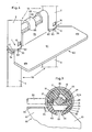
- the coupling 1 shown in FIGS. 1 to 3 connects two coaxial tubes 2, 3 of the same circular cross-section to one another on the end face.
- the tubes 2, 3 have two diametrically opposite, rectangular openings 5 adjacent to their end faces 4.
- a first coupling part 6 is snapped into the openings 5 of the tube 2, and a second coupling part 7 is snapped into the openings 5 of the tube 3.
- the coupling part 6 consists of a bushing 10, a coupling bolt 11 and a ring 12.
- the bushing 10 is divided into two identical halves in the plane of the drawing of FIG. 2 containing the axis 8 of the tubes 2, 3 and coupling 1, which are opposed to each other by two pins 14 which engage in conical holes 13 and project perpendicular to the parting plane are centered.
- Each sleeve half has a nose 16 protruding over the cylindrical outer circumference 15 of the sleeve 10 with a wedge surface 17 facing away from the ring 12 and a radial end face 18 facing the ring 12.
- the nose 16 sits approximately on a radially resilient tongue 20 formed by longitudinal slots 19 the width of the associated opening 5 and is snapped into this opening 5.
- a hub part 21 of the Bushing 10 encloses a cylindrical shaft 25 of the coupling pin 11.
- the coupling pin 11 is rotatably mounted in this hub part 21 and is axially immovable.
- two stop lugs 27 are then integrally formed on the shaft 25 on a head 26 of the coupling bolt 11 lying on the face of the bush 10. These interact with corresponding stop surfaces 28 of the sleeve 10 (FIG. 3).
- a hex flange 29 of the coupling pin 11 bears against the hub part 21.
- the corner dimension of this flange 29 is larger than the diameter of the head 26.
- the flange 29 is seated in an adapted hexagon recess 30 of the ring 12.
- the ring 12 has a constriction 31 with an inner diameter that is less than the corner dimension of the hexagonal flange 29, but larger than the diameter of the head 26.
- the ring 12 has two radial contact shoulders 32, which bear against the end faces 4 of the tubes 2, 3, and on both sides a conical centering projection 33 which is inserted into the tube ends. Between the contact shoulders 32, the ring 12 has two key surfaces 34. The ring 12 and thus the coupling pin 11 can be rotated by means of a key which engages in these surfaces. Offset to this key by 90 ° surfaces 34, the ring 12 has two radial blind holes 35. At least in the area of these blind holes 35, the diameter of the ring 12 corresponds to the diameter of the tubes 2, 3.
- the one-piece second coupling part 7 is cup-shaped and is fastened in the tube 3 in an analogous manner to the two-part bushing 10 in the tube 2.
- the coupling part 7 thus also has two radially resilient tongues 41 with lugs 42 formed by longitudinal slots 40, which extend into the openings 5 of the tube 3 are engaged.
- the end face of the bottom 43 of the coupling part 7 protruding into the interior of the tube 3 forms a convex cylindrical contact surface 44 for a bolt 45 of the coupling bolt 11.
- the bottom 43 is pierced by an axial slot 46 through which the bolt 45 fits.
- the support surface 47 of the bolt 45 facing the contact surface 44 is spherical and has the same radius of curvature as the contact surface 44.
- the sleeve 10, the ring 12 and the second coupling part 7 suitably consist of a dimensionally stable, heavy-duty plastic, e.g. made of polyamide, possibly with fiber reinforcement.
- the coupling described can be connected and released again very quickly by a rotation of 90 °, and it has the Advantage that it does not protrude beyond the diameter of the tubes 2, 3.
- the coupling described is particularly well suited for connecting column elements 53, 54 arranged vertically one above the other for a room divider if the column elements 53, 54 each consist of two vertical pipes 2, 3 with a circular cross-section, spaced from one another and connected by horizontal connecting rods 55 (FIG. 4).
- the pipes 2, 3 of these column elements placed one above the other are each connected to one another by a coupling 1.
- the columns 53, 54 carry dividing elements, for example dividing walls, cupboard or drawer elements.
- the lower, horizontal leg 61 of the carrier 60 has two indentations 62 in the shape of a segment of a circle for abutment on the two rings 12.
- a protrusion 63 protrudes from each of these indentations 62 and engages in the blind bores 35 of the rings 12 in the assembled state.
- Two fingers 65 bent over by 180 ° are formed on the vertical leg 64. In the assembled state, these fingers 65 grip around the connecting rods 55 and transmit the load to these rods.
- the fingers 65 are asymmetrical and leave a gap 66 open on one side and between them, which is wider than the finger width. This allows two identical ones on the same connecting rod 55
- Carrier 60 can be attached in mirror image to the center plane of the columns 53, 54.
- the fingers 65 of one carrier fit into the gaps 66 of the other carrier.
- the carrier 60 If the carrier 60 is inserted and a tray is placed on the carrier 60, this carrier is fixed and cannot be moved to either side.
- the carrier 60 also secures the rings 12. In addition, this configuration ensures that the couplings 1 are fully coupled, because if the rings 12 have not been rotated or only partially rotated, the carrier 60 hangs crookedly and the separating element in question cannot be used .
- the same supports 60 are also used at different heights of the column 53, 54. For this purpose, the tubes 2, 3 below each of the remaining connecting rods 55 have transverse bores corresponding to the blind holes 35. Because of this additional use of the supports 60, the rings 12 in the region of the blind bores 35 have the same diameter as the tubes 2, 3.
Landscapes
- Engineering & Computer Science (AREA)
- Architecture (AREA)
- General Engineering & Computer Science (AREA)
- Electromagnetism (AREA)
- Civil Engineering (AREA)
- Structural Engineering (AREA)
- Physics & Mathematics (AREA)
- Mechanical Engineering (AREA)
- Mutual Connection Of Rods And Tubes (AREA)
- Joints Allowing Movement (AREA)
- Joining Of Building Structures In Genera (AREA)
- Pivots And Pivotal Connections (AREA)
- Ladders (AREA)
- Separation Using Semi-Permeable Membranes (AREA)
- Quick-Acting Or Multi-Walled Pipe Joints (AREA)
Priority Applications (1)
| Application Number | Priority Date | Filing Date | Title |
|---|---|---|---|
| AT89810067T ATE61453T1 (de) | 1988-01-28 | 1989-01-25 | Kupplung zum loesbaren verbinden zweier koaxialer rohre und tragsaeule fuer einen raumteiler enthaltend die kupplung. |
Applications Claiming Priority (2)
| Application Number | Priority Date | Filing Date | Title |
|---|---|---|---|
| CH291/88A CH671615A5 (enExample) | 1988-01-28 | 1988-01-28 | |
| CH291/88 | 1988-01-28 |
Publications (2)
| Publication Number | Publication Date |
|---|---|
| EP0326523A1 EP0326523A1 (de) | 1989-08-02 |
| EP0326523B1 true EP0326523B1 (de) | 1991-03-06 |
Family
ID=4183647
Family Applications (1)
| Application Number | Title | Priority Date | Filing Date |
|---|---|---|---|
| EP89810067A Expired - Lifetime EP0326523B1 (de) | 1988-01-28 | 1989-01-25 | Kupplung zum lösbaren Verbinden zweier koaxialer Rohre und Tragsäule für einen Raumteiler enthaltend die Kupplung |
Country Status (9)
| Country | Link |
|---|---|
| US (1) | US4903924A (enExample) |
| EP (1) | EP0326523B1 (enExample) |
| AT (1) | ATE61453T1 (enExample) |
| CH (1) | CH671615A5 (enExample) |
| DE (1) | DE58900059D1 (enExample) |
| ES (1) | ES2021480B3 (enExample) |
| HK (1) | HK4692A (enExample) |
| SG (1) | SG71191G (enExample) |
| ZA (1) | ZA89677B (enExample) |
Families Citing this family (7)
| Publication number | Priority date | Publication date | Assignee | Title |
|---|---|---|---|---|
| US5127762A (en) * | 1989-03-03 | 1992-07-07 | Republic Tool & Mfg. Corp. | Connector assembly |
| EP1076779B1 (en) | 1998-05-08 | 2004-07-07 | Nandor Varnai | Device for making detachable tube-joint |
| US6669395B2 (en) * | 2002-02-19 | 2003-12-30 | Wen-Chang Wu | Connection structure of a lamp tube |
| US20050248156A1 (en) * | 2004-05-05 | 2005-11-10 | Pi-Hua Hsieh | Structure lamp pipe insert connector |
| DE102004023076A1 (de) * | 2004-05-11 | 2005-12-08 | Rennerich Gmbh | Einrichtung zum Verbinden koaxialer Rohre, insbesondere für Regalsysteme |
| US20120103924A1 (en) * | 2010-10-27 | 2012-05-03 | Shan-Chi Chuang | Curtain Pole Assembly Having Detachable Structure |
| CN110319083B (zh) * | 2019-08-02 | 2024-07-30 | 广州海方科技股份有限公司 | 一种卡扣组合结构 |
Family Cites Families (6)
| Publication number | Priority date | Publication date | Assignee | Title |
|---|---|---|---|---|
| GB190904598A (en) * | 1909-02-24 | 1909-08-12 | Alfred Bradley Johnson | Improvements in and relating to Couplings of Sectional Rods suitable for use in Cleaning Drains and like purposes. |
| US1960405A (en) * | 1932-05-20 | 1934-05-29 | Amor George William | Connection or coupling for tubular bodies |
| US2868602A (en) * | 1957-10-18 | 1959-01-13 | Drezner Lee | Furniture leg with insert |
| US3004784A (en) * | 1959-07-20 | 1961-10-17 | Tubular Structures Corp Of Ame | Coupling pin |
| ZA724424B (en) * | 1972-06-27 | 1973-09-26 | H Lawrence | Improvements in or relating to connector means and more particularly to connector means suitable for connecting together non-rotatable members |
| US3918821A (en) * | 1974-06-14 | 1975-11-11 | Komline Sanderson Eng Corp | Articulated connector |
-
1988
- 1988-01-28 CH CH291/88A patent/CH671615A5/de not_active IP Right Cessation
-
1989
- 1989-01-25 ES ES89810067T patent/ES2021480B3/es not_active Expired - Lifetime
- 1989-01-25 DE DE8989810067T patent/DE58900059D1/de not_active Expired - Fee Related
- 1989-01-25 AT AT89810067T patent/ATE61453T1/de not_active IP Right Cessation
- 1989-01-25 EP EP89810067A patent/EP0326523B1/de not_active Expired - Lifetime
- 1989-01-27 US US07/302,798 patent/US4903924A/en not_active Expired - Fee Related
- 1989-01-27 ZA ZA89677A patent/ZA89677B/xx unknown
-
1991
- 1991-08-24 SG SG711/91A patent/SG71191G/en unknown
-
1992
- 1992-01-16 HK HK46/92A patent/HK4692A/xx unknown
Also Published As
| Publication number | Publication date |
|---|---|
| US4903924A (en) | 1990-02-27 |
| SG71191G (en) | 1991-11-22 |
| DE58900059D1 (de) | 1991-04-11 |
| CH671615A5 (enExample) | 1989-09-15 |
| HK4692A (en) | 1992-01-17 |
| ES2021480B3 (es) | 1991-11-01 |
| EP0326523A1 (de) | 1989-08-02 |
| ZA89677B (en) | 1989-10-25 |
| ATE61453T1 (de) | 1991-03-15 |
Similar Documents
| Publication | Publication Date | Title |
|---|---|---|
| DE102007037242B4 (de) | Befestigungseinrichtung mit Toleranzausgleich | |
| EP0126181B1 (de) | Trinkgefäss mit Halter | |
| DE2217490C3 (de) | Halterung einer schwimmend gelagerten Mutter an einem Werkstück | |
| EP2318723B1 (de) | Befestigungsanordnung mit toleranzausgleich | |
| DE69618347T2 (de) | Einsatz für einen probenröhrchenhalter | |
| DE69006643T2 (de) | Scharniervorrichtung zur Drehkupplung zweier Elemente. | |
| EP1215401B1 (de) | Vorrichtung zum Verbinden von Bauteilen | |
| EP0686748B1 (de) | Scharnierstiftloses wartungsfrei gelagertes Blechscharnier für Kraftwagentüren | |
| DE202006012493U1 (de) | Befestigungseinrichtung mit Toleranzausgleich | |
| DE102021105786A1 (de) | Toleranzausgleichsanordnung | |
| EP1386051A1 (de) | Universelle führungseinrichtung für schiebetüren eines möbels | |
| DE19533138C1 (de) | Vorrichtung zur Verbindung von Blechteilen einer Rohbaukarosserie eines Kraftfahrzeugs | |
| DE60020533T2 (de) | Tragstruktur eines Gabelrohres in einem Fahrrad | |
| EP0232485B1 (de) | Dübel zur Lagefixierung eines Bauteils an einem Referenzteil | |
| DE202010009776U1 (de) | Eine Nabe für ein Gelände-Motorrad | |
| DE69117867T2 (de) | Endauschlussstück | |
| EP0326523A1 (de) | Kupplung zum lösbaren Verbinden zweier koaxialer Rohre und Tragsäule für einen Raumteiler enthaltend die Kupplung | |
| DE4112133A1 (de) | Hebelwerk, insbesondere fusshebelwerk fuer kraftfahrzeuge | |
| DE69918547T2 (de) | Vorrichtung zum herstellen einer lösbaren rohrverbindung | |
| EP0404765A1 (de) | Lageranordnung für eine andruckwalze einer druckeinrichtung. | |
| DE69609057T2 (de) | Eine Vorrichtung für die Befestigung einer Stange auf eine Abstützung, wie zum Beispiel eine Mauer | |
| EP3825265B1 (de) | Klammervorrichtung zum halten eines behälters | |
| DE3732895C2 (enExample) | ||
| DE19915491C2 (de) | Fußkreuz, insbesondere für einen Infusionsständer | |
| EP3574813B1 (de) | Scharnier für eine toilettensitzgarnitur |
Legal Events
| Date | Code | Title | Description |
|---|---|---|---|
| PUAI | Public reference made under article 153(3) epc to a published international application that has entered the european phase |
Free format text: ORIGINAL CODE: 0009012 |
|
| AK | Designated contracting states |
Kind code of ref document: A1 Designated state(s): AT BE CH DE ES FR GB IT LI NL SE |
|
| 17P | Request for examination filed |
Effective date: 19890706 |
|
| 17Q | First examination report despatched |
Effective date: 19900118 |
|
| GRAA | (expected) grant |
Free format text: ORIGINAL CODE: 0009210 |
|
| AK | Designated contracting states |
Kind code of ref document: B1 Designated state(s): AT BE CH DE ES FR GB IT LI NL SE |
|
| ITF | It: translation for a ep patent filed | ||
| REF | Corresponds to: |
Ref document number: 61453 Country of ref document: AT Date of ref document: 19910315 Kind code of ref document: T |
|
| REF | Corresponds to: |
Ref document number: 58900059 Country of ref document: DE Date of ref document: 19910411 |
|
| ET | Fr: translation filed | ||
| GBT | Gb: translation of ep patent filed (gb section 77(6)(a)/1977) | ||
| PLBE | No opposition filed within time limit |
Free format text: ORIGINAL CODE: 0009261 |
|
| STAA | Information on the status of an ep patent application or granted ep patent |
Free format text: STATUS: NO OPPOSITION FILED WITHIN TIME LIMIT |
|
| PGFP | Annual fee paid to national office [announced via postgrant information from national office to epo] |
Ref country code: NL Payment date: 19920131 Year of fee payment: 4 |
|
| 26N | No opposition filed | ||
| PGFP | Annual fee paid to national office [announced via postgrant information from national office to epo] |
Ref country code: AT Payment date: 19930114 Year of fee payment: 5 Ref country code: FR Payment date: 19930114 Year of fee payment: 5 |
|
| PGFP | Annual fee paid to national office [announced via postgrant information from national office to epo] |
Ref country code: SE Payment date: 19930120 Year of fee payment: 5 |
|
| PGFP | Annual fee paid to national office [announced via postgrant information from national office to epo] |
Ref country code: BE Payment date: 19930126 Year of fee payment: 5 |
|
| PGFP | Annual fee paid to national office [announced via postgrant information from national office to epo] |
Ref country code: ES Payment date: 19930209 Year of fee payment: 5 |
|
| PG25 | Lapsed in a contracting state [announced via postgrant information from national office to epo] |
Ref country code: NL Effective date: 19930801 |
|
| NLV4 | Nl: lapsed or anulled due to non-payment of the annual fee | ||
| PGFP | Annual fee paid to national office [announced via postgrant information from national office to epo] |
Ref country code: GB Payment date: 19931210 Year of fee payment: 6 |
|
| PG25 | Lapsed in a contracting state [announced via postgrant information from national office to epo] |
Ref country code: AT Effective date: 19940125 |
|
| PG25 | Lapsed in a contracting state [announced via postgrant information from national office to epo] |
Ref country code: SE Effective date: 19940126 Ref country code: ES Free format text: LAPSE BECAUSE OF NON-PAYMENT OF DUE FEES Effective date: 19940126 |
|
| PG25 | Lapsed in a contracting state [announced via postgrant information from national office to epo] |
Ref country code: BE Effective date: 19940131 |
|
| BERE | Be: lapsed |
Owner name: EMBRU-WERKE MANTEL & CIE Effective date: 19940131 |
|
| PG25 | Lapsed in a contracting state [announced via postgrant information from national office to epo] |
Ref country code: FR Effective date: 19940930 |
|
| REG | Reference to a national code |
Ref country code: FR Ref legal event code: ST |
|
| PG25 | Lapsed in a contracting state [announced via postgrant information from national office to epo] |
Ref country code: GB Effective date: 19950125 |
|
| EUG | Se: european patent has lapsed |
Ref document number: 89810067.2 Effective date: 19940810 |
|
| GBPC | Gb: european patent ceased through non-payment of renewal fee |
Effective date: 19950125 |
|
| REG | Reference to a national code |
Ref country code: CH Ref legal event code: NV Representative=s name: PATENTANWALTS-BUREAU ISLER AG |
|
| REG | Reference to a national code |
Ref country code: ES Ref legal event code: FD2A Effective date: 19990201 |
|
| PGFP | Annual fee paid to national office [announced via postgrant information from national office to epo] |
Ref country code: DE Payment date: 20011219 Year of fee payment: 14 |
|
| PG25 | Lapsed in a contracting state [announced via postgrant information from national office to epo] |
Ref country code: DE Free format text: LAPSE BECAUSE OF NON-PAYMENT OF DUE FEES Effective date: 20030801 |
|
| PG25 | Lapsed in a contracting state [announced via postgrant information from national office to epo] |
Ref country code: IT Free format text: LAPSE BECAUSE OF NON-PAYMENT OF DUE FEES;WARNING: LAPSES OF ITALIAN PATENTS WITH EFFECTIVE DATE BEFORE 2007 MAY HAVE OCCURRED AT ANY TIME BEFORE 2007. THE CORRECT EFFECTIVE DATE MAY BE DIFFERENT FROM THE ONE RECORDED. Effective date: 20050125 |
|
| PGFP | Annual fee paid to national office [announced via postgrant information from national office to epo] |
Ref country code: CH Payment date: 20071116 Year of fee payment: 20 |
|
| REG | Reference to a national code |
Ref country code: CH Ref legal event code: PL |