EP0326435A2 - Systèmes de télévision à définition modifiée - Google Patents
Systèmes de télévision à définition modifiée Download PDFInfo
- Publication number
- EP0326435A2 EP0326435A2 EP89300869A EP89300869A EP0326435A2 EP 0326435 A2 EP0326435 A2 EP 0326435A2 EP 89300869 A EP89300869 A EP 89300869A EP 89300869 A EP89300869 A EP 89300869A EP 0326435 A2 EP0326435 A2 EP 0326435A2
- Authority
- EP
- European Patent Office
- Prior art keywords
- components
- signal
- production
- receiver
- frequency
- Prior art date
- Legal status (The legal status is an assumption and is not a legal conclusion. Google has not performed a legal analysis and makes no representation as to the accuracy of the status listed.)
- Withdrawn
Links
Images


Classifications
-
- H—ELECTRICITY
- H04—ELECTRIC COMMUNICATION TECHNIQUE
- H04N—PICTORIAL COMMUNICATION, e.g. TELEVISION
- H04N7/00—Television systems
- H04N7/08—Systems for the simultaneous or sequential transmission of more than one television signal, e.g. additional information signals, the signals occupying wholly or partially the same frequency band, e.g. by time division
-
- H—ELECTRICITY
- H04—ELECTRIC COMMUNICATION TECHNIQUE
- H04N—PICTORIAL COMMUNICATION, e.g. TELEVISION
- H04N11/00—Colour television systems
- H04N11/24—High-definition television systems
- H04N11/30—High-definition television systems with transmission of the extra information by means of quadrature modulation
-
- H—ELECTRICITY
- H04—ELECTRIC COMMUNICATION TECHNIQUE
- H04N—PICTORIAL COMMUNICATION, e.g. TELEVISION
- H04N19/00—Methods or arrangements for coding, decoding, compressing or decompressing digital video signals
- H04N19/60—Methods or arrangements for coding, decoding, compressing or decompressing digital video signals using transform coding
- H04N19/62—Methods or arrangements for coding, decoding, compressing or decompressing digital video signals using transform coding by frequency transforming in three dimensions
-
- H—ELECTRICITY
- H04—ELECTRIC COMMUNICATION TECHNIQUE
- H04N—PICTORIAL COMMUNICATION, e.g. TELEVISION
- H04N19/00—Methods or arrangements for coding, decoding, compressing or decompressing digital video signals
- H04N19/60—Methods or arrangements for coding, decoding, compressing or decompressing digital video signals using transform coding
- H04N19/63—Methods or arrangements for coding, decoding, compressing or decompressing digital video signals using transform coding using sub-band based transform, e.g. wavelets
Definitions
- This invention relates to high-definition television (HDTV) systems.
- a very important feature of new systems is whether they are "receiver-compatible,” which means that existing receivers would be able to decode and display the new transmissions.
- Another important feature is “channel compatibility,” which means that the new signals could be transmitted properly in the 6-MHz channels now used for NTSC.
- Present broadcasters believe that receiver compatibility is necessary in order to continue serving the existing 140 million NTSC receivers.
- the incorporation of the NTSC signal structure in new systems means that they will be inefficient in the transmission of information, and that it will therefore be impossible to achieve true HDTV performance with such receiver-compatible systems.
- One proposal is to start with an intermediate quality enhanced-definition (EDTV) system that is receiver-compatible and then move to a noncompatible system in a later stage. To employ this strategy the EDTV system must be a technological "bridge" to the final system, and preferably should be compatible with the new receivers to be used in the final system.
- EDTV intermediate quality enhanced-definition
- a high-definition television system for processing and transmitting a production television signal (e.g., a signal originating in a television camera or a production facility).
- the production signal is spatially (preferably spatiotemporally) filtered to remove frequency components of relatively lesser importance to perceived image quality (e. g., components with both high spatial and high temporal frequency content), and the selected remaining components, i.e., components of relatively greater importance to perceived image quality, are transmitted using double-sideband quadrature modulation with a Nyquist bandwidth filling the available channel (e g. 6 MHz).
- the resulting system greatly increases the quality (e.g., spatial resolution and motion smoothness) of the received image over that possible using NTSC.
- a bank of three-dimensional, quadrature-mirror filters e.g., cascades of separable, one-dimensional quadrature-mirror filters
- the transmitted components all require the same bandwidth for transmission and are time-multiplexed on the channel
- frame stores are used to avoid loss of transmission time during horizontal and vertical retrace intervals, and to allow for separate scanning standards for camera, channel, and display
- audio and control data are time-multiplexed with the selected image components
- the selected components having no DC value are adaptively modulated to improve the perceived signal-to-noise ratio at the receiver
- two independent production television signals are concurrently transmitted by dividing the frame store into sections.
- the invention features selecting the transmitted components using filters that produce a generally diamond-shaped frequency response in both the spatial and spatiotemporal planes. This improves image quality by taking advantage of the human eye's reduced sensitivity to spatial detail in rapidly moving objects and to diagonal spatial detail even in motionless objects.
- the invention features varying the selection of components transmitted in accordance with the amount of motion in the image.
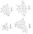
- components representing higher temporal and lower spatial frequencies e.g., the components represented by blocks R, G, B, V1, T1, H1, T2, T3, T4 in Fig. 4
- components representing lower temporal and higher spatial frequencies e.g., blocks R, G, B, V1, T1, H1, V2, V1, VH, V2 in Fig. 4
- This technique though it may result in some blurring of moving objects, provides an overall improvement in perceived image quality, for a given total channel bandwidth.
- the invention features taking advantage of the human eye's reduced sensitivity to noise in high frequency components by sharing the channel with additional data, such as digital audio, during transmission of such components.
- the high frequency component is attenuated and superimposed on the analog version of the additional data, with the attenuation selected so that the difference in adjacent levels of the analog version of the data is greater than the sum of the peak amplitude of the attenuated component and the expected noise on the channel.
- the invention features providing a true diamond-shaped frequency response by diagonally addressing frames of image data held in a frame store and passing the diagonally-addressed data through vertical and horizontal filters.
- the invention features a modulation technique that exhibits graceful deterioration of signal quality with a less-than-perfect transmission channel.
- Image data is transmitted by double-sideband quadrature modulation of two baseband signals onto a single carrier with the baseband signals being derived from closely related areas of the image so as to reduce the effect of demodulation errors in the receiver.
- one baseband signal is derived from the odd lines of a stored frame of image data and the other signal from adjacent even lines, so that the effect of demodulation errors at the receiver is merely to reduce vertical resolution.
- the invention features a high-definition television receiver adaptable to receiving a variety of transmission formats.
- the receiver has three principal sections: (1) front-end circuitry with a tuner for selecting and demodulating the received RF signal to provide a received video signal; (2) digital processing and associated circuitry for processing the video signal, the circuitry including a decoder for demodulating the video signal to provide image and control information in the form of a plurality of frequency components, an input memory including at least one input frame store for storing the image and control information, an input bus for transferring the image and control information from the input memory, a programmable interpolator for generating display data from the frequency components, a control module for responding to the control information and issuing control instructions to the programmable interpolator, and an output bus for transferring display data from the programmable interpolator; and (3) display circuitry including a screen-refresh memory for storing the display data received on the output bus, a display device for displaying images represented by the received data, and circuitry for transforming the display
- the programmable interpolator includes means for performing spatial and temporal interpolation for improving image quality; means for interfacing with a source of digital video is included in the processing section; the front-end circuitry is tunable but not programmable; the display circuitry is not programmable; the screen-refresh memory holds the display data in a compressed form and circuitry provided for transforming the compressed display data includes interpolation and transformation circuitry; the decoder includes circuitry capable of being programmed to distinguish between a predetermined range of possible modulation methods (e.g., the decoder is capable of demodulating an NTSC transmission, to provide receiver-compatibility); the programmable interpolation means is capable, under the control of the control module, of generating the display data at the same frame rate from image information of varying spatial and temporal resolution as represented by different sets of the frequency components.
- the invention features an EDTV system in which luminance and chrominance are one dimensionally filtered so as substantially to eliminate crosstalk, and enhancement information is added to increase the vertical resolution of the lower horizontal frequencies and to increase the horizontal resolution of the lower vertical frequencies.
- enhancement information is transmitted by double-sideband quadrature modulation, with two baseband signals each one half of the total bandwidth available for the enhancement information; enhancement information is transmitted at one half the normal frame rate so that it can have double the resolution, and intervening frames are filled in by interpolation at the receiver.
- the invention features a receiver-compatible, enhanced-definition television (EDTV) system in which the enhancement information is added to the NTSC signal by usurping a fraction of the image height and providing the remaining area with the same aspect ratio as that of EDTV image.
- EDTV enhanced-definition television
- the horizontal resolution of chrominance is doubled by subsampling a signal that has twice the normal resolution, so that every point of the higher resolution original is sampled once per two full frames; and missing points are filled in at the receiver by temporal interpolation.
- the invention features a receiver-compatible, enhanced-definition television (EDTV) in which the enhancement signals are adaptively modulated to suppress channel noise.
- EDTV enhanced-definition television
- the invention When applied to NTSC incompatible systems, the invention is capable of achieving as high picture and sound quality as possible in an analog channel of a prescribed bandwidth, and in particular, within existing 6-MHz channels.
- Such NTSC incompatible embodiments are useful for cable transmission or as the second stage in going to HDTV in broadcasting, the first EDTV stage being receiver-compatible.
- the invention is capable of operating properly in real cable and broadcasting channels, deteriorating gracefully with less-than-perfect transmissions systems.
- Double-sideband quadrature modulation is meant to include not only classical quadrature modulation of a carrier by two amplitude modulated signals but also all equivalent modulation schemes, e.g., combined phase and amplitude modulation.
- the term is also not meant to limit in any way the particular implementation, and thus, for example, includes not only actual modulation of a carrier followed by bandlimiting but also direct synthesis of the bandlimited transmitted signal from a library of stored waveforms.
- the temporal response of the visual system is lower for chrominance than for luminance, so an overall saving is possible by using different frame rates for the two kinds of signals.
- a lower spatial resolution for chrominance, both vertically and horizontally, is also used.
- NTSC uses only a lower horizontal resolution.
- Any particular frame rate represents a tradeoff between spatial and temporal resolution.
- the best tradeoff depends on the amount of motion. We therefore use different frame rates, and achieve different spatial resolution, according to the degree of motion. We also use, on average, lower frame rates than now used in TV, giving weight to spatial and temporal resolution more nearly as done in motion picture practice. This is possible because the frame store permits an arbitrarily high display frame rate, eliminating large-area flicker.
- NTSC uses a wideband luminance and narrow band chrominance.
- a better alternative for our purposes is "mixed highs," which means narrow band red, green, and blue signals (RGB) plus a luminance high-frequency component.
- the filtering used is two- or three-dimensional (horizontal, vertical, and temporal) rather than one-dimensional as in NTSC. This does not save channel capacity directly, but it facilitates using different frame rates for the different components, as well as noise reduction.
- the mixed highs system permits adaptive modulation of all of the signal components that have no dc-component, as disclosed in our copending application (herein incorporated by reference) Serial No. 61,140, filed June 6, 1987.
- the general idea is to raise the level of the highs components, which are typically very small, especially in the blank areas of the image where noise is most evident.
- the signals are multiplied by a factor, greater than one, as large as possible without channel overload.
- the components are divided by the same factor, at the same time greatly decreasing channel noise.
- Factors are assigned to blocks in spatiotemporal signal space and the actual factor used at any pel is chosen by interpolation, both in the transmitter and receiver. The block factors are transmitted to the receivers along with other control data.
- This psychophysical phenomenon can be utilized to advantage by inserting an extra signal into each highs component.
- the extra data can be used to increase resolution, to improve the operation of the noise-reduction process by using separate adaptation factors for each component, or for any other purpose.
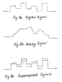
- the general idea is to reduce the amplitude of the highs component and superimpose it on a multi-level digital signal, as illustrated in Figs. 8A-8C. As long as the highs component summed with the expected noise does not exceed the separation between levels, the two signals can be separated perfectly at the receiver. Naturally, this reduces the arithmetic SNR by a factor equal to the number of levels.
- a TV receiver capable of decoding transmissions making use of all of the principles mentioned must have a fair amount of computational power. Using modern components and techniques, such a receiver appears to be quite practical. By arranging the receiver so that the computation section that actually accepts the various signal components and arranges them properly has the bus-structured architecture of a computer, substantial economies are possible. This will be especially true because of the very large volume in which TV receivers are typically manufactured. This structure also makes it possible to design the receiver in such a way that it can readily decode and display NTSC, EDTV, and HDTV, the latter two in a variety of formats. In this connection, it is highly desirable that all of the programmability be located in the computation section, while the other sections, which involve analog components, be fixed. Of course, the analog "front end" must be tunable.
- the processor can be controlled by a small amount of digital data transmitted along with the signal. It can also be controlled or even modified by adding hardware or software modules that plug into one of the buses.
- the receiver must be able to recognize each of the various modulation methods without instruction so that the demodulator may be suitably configured. To achieve this result, the receiver, when first tuned to a signal, may be caused to initiate a search routine in which the several demodulator configurations are employed in sequence. The processor section can then analyze the demodulated signal to determine which type of modulation is in use. Obviously only previously agreed-upon modulation methods may be detected in this manner. It is, of course, possible to increase the repertory of allowable modulation methods by adding some plug-in units, provision for which can be made in the original design.
- each receiver For cable use, it is necessary to encrypt the signal to prevent unauthorized viewing. Of course, authorized viewers must gain access to the proper programs, such access preferably being provided by addressing each receiver individually through the transmission system.
- the signal is inherently encrypted, so every receiver requires a decoding key.
- Each receiver can be assigned an address, much like a telphone number. This address can be transmitted at the beginning of the program, or periodically, and recognized by the processor. Following the address, a code word can be sent, utilized only after the correct address, that sets up the processor to operate properly.
- the TV camera operates at high line and frame rates, preferably using progressive scanning.
- the resulting signal is divided into a number of components by three-dimensional filters, i e., by filters operating in three-dimensional spatiotemporal frequency space.
- the components consist of rectangular blocks in this space, so that the three-dimensional filters are separable, meaning that they can be implemented as a cascade of one-dimensional filters, which are less expensive than nonseparable filters.
- the channel capacity required to transmit such a component is proportional to the volume of the corresponding block in three-dimensional frequency space, and preferably all blocks are of equal volume so as to simplify multiplexing.
- the video signals from the various blocks are time-multiplexed into one of the two baseband signals, and the latter are then quadrature modulated onto the carrier.
- Multiplexing can be done in many ways. In order to keep the temporal relationship among the various signals as close as possible to what prevailed in the input signal, thus minimizing the total amount of buffering needed, one scan line from each block is transmitted in sequence before a second scan line is used. Audio and miscellaneous data is multiplexed along with the block information.
- the received signal is decoded and buffered (e.g., stored in a frame store).
- the various components are taken out of the buffer, interpolated, and assembled in correct geometrical arrangement, into a second buffer.
- Account is taken of the frame rate of each signal, any adaptive modulation that may have been used, whether it is luminance or chrominance, and what its frequency range is.
- Data is read out of the second buffer, interpolated, and used to drive the display device, which operates at a higher line and frame rate. Since the display is not programmable, all kinds of input signals result in the same line and frame rate on the display for any one receiver, but all receivers need not have the same display standards Note that the particular arrangement of the display section depends on the cost of components.
- this system Since the resolution of this system is so high compared with NTSC, it can be used to transmit two or more independent signals simply by dividing the image area into sections. Of course, the receiver must "know" what arrangement is used so that proper decoding is done, and this is indicated by a code word in the data channel.
- the invention also has application to receiver-compatible systems.
- unmodified existing receivers will display a satisfactory picture
- new receivers identical to that discussed above for the noncompatible version, will display an improved picture, and possibly improved audio.
- the studio and transmission equipment must be capable of high-definition performance. The required signal processing is actually somewhat more complicated than in the noncompatible scheme.
- the compatible system can be thought of as using the HDTV format for a fraction of each frame and the NTSC format for the balance.
- the standard receiver displays only the NTSC portion, showing bars for the usurped area, while the smart receiver combines all the information to produce an enhanced wide aspect ratio image.
- the limited bandwidth available for enhancement information makes it preferable to forego scene-adaptive variable frame rate and motion compensation in receiver-compatible systems.
- Encoder 10 includes high-rate production system 12 for producing a production signal to be processed and transmitted to a television receiver, analog-to-digital converter 14, quadrature mirror filter bank 16 for dividing the production signal into fourteen components (nine of which are used at any one time), adaptive modulator 17 for adaptively compressing some of the high-frequency components, multiplexer 18 for selecting nine of the fourteen components (based on commands from control circuit 20), storage element 22 for storing the selected components and producing two streams of data, control circuit 20 for controlling multiplexer 18 and storage element 22, digital-to-analog converters 24 and 26, 3-megahertz low-pass filters 28 and 30, and quadrature modulator 32 for quadrature-modulating the two signals from storage element 22 onto carrier 34, which has a bandwidth of 6 megahertz.
- Encoder 10 may also include summer 35, for superimposing the analog signals onto a multilevel digital signal.
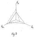
- the fourteen video components produced by filter bank 14 are best illustrated in three-dimensional spatio-temporal frequency space.
- a diagram of three-dimensional frequency space is shown in Fig. 3.
- the spectrum of moving video signals may be displayed with respect to vertical and horizontal spatial frequency axes 74 and 76, respectively, and with respect to temporal frequency axis 78.
- the three-dimensional frequency space may be divided into blocks 80, corresponding to possible components of data contained in the moving video signals.
- Figs. 4A through 4E The possible selections of the components are illustrated in three-dimensional frequency space in Figs. 4A through 4E.
- the three red, green, and blue chrominance "lows" signals represented by block 82 in Fig. 4A are always transmitted, as are the three luminance "highs" signals V1, H1, and T1, represented by blocks 84, 86, and 88, respectively, in Fig. 4B.
- the three components V2, VH, and H2 represented by blocks 90, 92, and 94 in Fig. 4C are also transmitted.
- the three components VT, HT, and T2 represented by blocks 96, 98, and 100 in Fig. 4D are transmitted.
- Two or more images may be transmitted simultaneously along a single carrier, at the expense of lower spatial or temporal resolution for each image, or a reduction in size for each image.
- the horizontal, vertical, or temporal resolution of each of the various components of the production signal may be varied as desired to accomodate such a scheme.
- the total number of components associated with each image may also be varied as desired.
- multiplexer 18 multiplexes the nine components, along with digital audio information and data, into storage element 22.
- Information is read out of storage in two streams, corresponding to odd and even scan lines, on a line-sequential basis, under the control of control circuit 20. Each line is read successively from each component before the next line is read out.
- Digital-to-analog converters 24 and 26 convert the two data streams into analog form.
- 3-Megahertz low-pass filters 28 and 30 filter the two data streams, and quadrature modulator 32 quadrature-modulates the two resultant 3-megahertz signals onto carrier signal 34, which has a bandwidth of 6 megahertz.
- Adaptive modulator 17 improves the signal-to-noise ratio for the transmission system by adaptively modulating the luminance components, so as to raise the signal strength where the signal strength is low.
- Adaptive modulator 17 also produces adaptation information, which is multiplexed into the baseband signals, so that receiver 36 may adaptively demodulate the luminance components in response to the adaptation information.
- Receiver 36 consists of input section 38, display section 40, and processing section 42.
- Input section 38 includes antenna 44 for receiving signals, tuner 46 for selecting a channel, detector 48 for detecting the signals selected by tuner 46, analog-to-digital converter 50, and input frame store 52 for storing the digitized signals.
- Input frame store 52 interfaces with input bus 54.
- analog-to-digital converter 50 may be placed before detector 48, so that detection may be done, digitally, in order to facilitate possible analog modulation schemes.
- Input section 38 is tunable, but not programmable. For a wide variety of input formats, it maintains in input frame store 52 a digital version of a complete "frame" as transmitted, but not in the form required for display.
- Programmable interpolator 68 receives signals from input frame store 52 via input bus 54, rearranges and interpolates the signals for storage in screen-refresh memory 56 and delivers the signals to output bus 58.
- Programmable interpolator 68 is supervised by control module 70, which receives programming data from input bus 54, and which interfaces with output bus 58.
- Third-party modules 72 which interface with input bus 54 and output bus 58, may provide signal enhancement, or may interface with digital signal sources, such as fiber-optic transmission lines.
- Display section 40 is not programmable.
- Screen-refresh memory 56 receives image data from programmable interpolator 68 and enhancement data and other data from third-party modules 72 and control module 70, via output bus 58.
- Screen-refresh memory 56 holds the image data in correct geometrical arrangement, at a standard frame and line rate, (not necessarily the frame and line rates transmitted or displayed) and in some slightly compressed form.
- the data is delivered to fixed interpolator 60, digital-to-analog converter 62, and 3-by-3 matrix transform 64, which process the analog signal for display on picture tube 66.
- All receivers 36 need not have the same display standard, but all kinds of signals received would be displayed at the same standard in any one receiver. A minimum would probably be 1200 lines, 60 frames per second progressively scanned, but higher would be better.
- Programmable interpolator 68 or control module 70 may include a decoding key, such as a decoding card for decoding the transmitted signals, that can control access to the television transmission system.
- programmable interpolator 68 or control module 70 of each receiver might store a unique address, so that messages might be sent to individual receivers granting access to the television transmission system as previously arranged.
- Programmable interpolator 68 in processing section 42 in display section 40 may provide improved temporal resolution by compensating for movement between successive frames. Thus, intermediate frames may be reconstructed, up to the maximum frame rate of which the display is capable.
- adaptive modulator 17 is used in encoder 10, then programmable interpolator 68 or control module 70 can receive the adaptation information produced by adaptive modulator 17 and transmitted along carrier 34, and adaptively demodulate the luminance components.
- a high-rate production system is used, preferably with at least 600 scan lines, 660 pels/line, and 60 fps, progressively scanned.
- the wideband RBG output signals are 3x3 matrix transformed to Y′I′Q′, which are like the NTSC components except for the resolution and scanning standards.
- Y′ is low-pass filtered to 360 lines vertical resolution and 330 pels horizontal resolution, and the highs are then formed as the difference between Y′ and its filtered version.
- Y′I′Q′ are low-pass filtered, subsampled, and filtered to form standard NTSC signals, which are then put into composite form in the normal manner and stored.
- the highs signal is separated into vertical and horizontal components by quadrature-mirror filters and stored.
- the highs signal can be adaptively modulated for noise suppression or can be placed "over" a digital signal, which in this case would in all likelihood be digital audio.
- the two signals are taken out of storage and combined to produce the enhanced signal, with NTSC occupying the center 75% of the picture height (360 lines) and the enhancement information the remaining 25% (120 lines).
- the normal receiver sees NTSC for the most part, the enhancement information forming bars at top and bottom.
- FIG. 6 A block diagram of the receiver-compatible system is shown in Fig. 6.
- the production system operates at least at 60 fps, progressively scanned, with resolution at least 600 high by 660 wide, with a 16:9 aspect ratio.
- the RGB signals are converted to Y′I′Q′ in an analog matrix and digitized.
- the subsequent operations are filtering, frame-rate conversion, storage, retrieval, modulation, and multiplexing, under the guidance of the control circuitry 20.
- Filters 1 and 2 confine the passband to 600 by 660.
- Filters 3 and 4 isolate the vertical enhancement data, and filters 5 and 6 isolate the horizontal enhancement data.
- Filters 7 and 8 limit the luminance bandwidth for the NTSC signal to 330 by 360, while filters 9 and 10 limit chrominance bandwidth to 126 by 360.
- Units 11-14 involve temporal filtering and subsampling. The NTSC luminance is reduced to 30 fps, interlaced, while luminance enhancement is reduced to 15 fps probably by 4th-order interlace.
- Chrominance is reduced to 15 fps by horizontal subsampling, so that it can be received compatibly on the NTSC receivers but expanded to the full 126 pels resolution by temporal interpolation (for the fixed areas) in the EDTV receiver. Spatial interpolation could be used for the moving areas in the EDTV receiver, as in MUSE. After frame-rate conversion, the chrominance information is stored.
- Data is retrieved from the stores by the control unit in the time relationship required for the final signal, e.g., NTSC for the middle 360 lines and enhancement for the top and bottom 60 lines each.
- Luminance enhancement is separated into even and odd-line information for the sake of the quadrature modulator 17.
- Information from store 16 feeds the NTSC modulator.
- the multiplexer also supervised by control circuitry 20, selects the appropriate signal for output.
- the smart receiver separates the various components and combines them to produce an EDTV picture.
- the NTSC luminance component is one-dimensional filtered to a horizontal resolution of 330 pels and it is 360 lines high. Since the sound carrier cannot be interrupted during the 120 lines used for enhancement, only 5.5 MHz of channel bandwidth is available. Using a carrier 1.5 MHz above the normal carrier, two baseband signals of 1.75 MHz can be used, for a total bandwidth of 5.5 MHz, or 11 million samples/sec. With about 60 microsec available on each line, 660 samples per sec are transmitted. We choose to form this 660x120 block (30/sec) into two 330x240 blocks, 15/sec.
- every other chrominance sample is chosen, in an off set pattern, from an original chrominance signal (separately for I and Q) which has 126 pels/picture width. Every sample is chosen at 15 fps.
- This technique which is used in some proposed HDTV systems, produces unacceptable flicker on standard receivers when used for luminance, but because of the lower temporal resolution of the visual system for chrominance than for luminance, little flicker is seen in chrominance.
- pels in successive frames although derived from adjacent points in the high resolution original, are deposited at the same point.
- temporal interpolation is used to fill in the missing samples in each frame. The net result is that the chrominance signals are 126x360, which is quite acceptable.
Applications Claiming Priority (2)
| Application Number | Priority Date | Filing Date | Title |
|---|---|---|---|
| US07/149,673 US4979041A (en) | 1988-01-28 | 1988-01-28 | High definition television system |
| US149673 | 1988-01-28 |
Publications (2)
| Publication Number | Publication Date |
|---|---|
| EP0326435A2 true EP0326435A2 (fr) | 1989-08-02 |
| EP0326435A3 EP0326435A3 (fr) | 1990-12-12 |
Family
ID=22531324
Family Applications (1)
| Application Number | Title | Priority Date | Filing Date |
|---|---|---|---|
| EP19890300869 Withdrawn EP0326435A3 (fr) | 1988-01-28 | 1989-01-30 | Systèmes de télévision à définition modifiée |
Country Status (3)
| Country | Link |
|---|---|
| US (1) | US4979041A (fr) |
| EP (1) | EP0326435A3 (fr) |
| JP (1) | JPH01265683A (fr) |
Cited By (4)
| Publication number | Priority date | Publication date | Assignee | Title |
|---|---|---|---|---|
| EP0400756A2 (fr) * | 1989-06-02 | 1990-12-05 | Koninklijke Philips Electronics N.V. | Méthode et appareil de traitement numérique d'un signal supplémentaire de télévision haute définition |
| DE3939829A1 (de) * | 1989-12-01 | 1991-06-06 | Grundig Emv | Sender zur erzeugung von videosignalen unterschiedlicher bildbreiten- zu bildhoehen-verhaeltnisse und empfaenger zur darstellung von videosignalen |
| DE4041708A1 (de) * | 1989-12-27 | 1991-07-04 | Nippon Television Network | Fernsehsystem |
| DE4102935A1 (de) * | 1990-02-01 | 1991-08-08 | Nippon Television Network | Fernsehsystem |
Families Citing this family (19)
| Publication number | Priority date | Publication date | Assignee | Title |
|---|---|---|---|---|
| US5179442A (en) * | 1989-06-02 | 1993-01-12 | North American Philips Corporation | Method and apparatus for digitally processing a high definition television augmentation signal |
| FR2651402B1 (fr) * | 1989-08-22 | 1991-10-25 | Europ Rech Electr Lab | Dispositif de conversion de frequence trame et du nombre de lignes pour un recepteur de television haute definition. |
| US5068728A (en) * | 1990-06-22 | 1991-11-26 | Albert Macovski | Compatible increased aspect ratio television system |
| KR940006735B1 (ko) * | 1991-01-22 | 1994-07-27 | 삼성전자 주식회사 | 지상동시방송방식 고품위 텔레비젼의 인코딩장치 및 방법 |
| NL9101080A (nl) * | 1991-06-24 | 1993-01-18 | Koninkl Philips Electronics Nv | Inrichting voor het splitsen van een digitaal geinterlinieerd televisie signaal in componenten. |
| US5272530A (en) * | 1991-11-01 | 1993-12-21 | Aware, Inc. | Method and apparatus for coding motion pictures utilizing motion compensation |
| US5301020A (en) * | 1991-11-01 | 1994-04-05 | Aware, Inc. | Method and apparatus for coding motion pictures utilizing motion compensation |
| US5280343A (en) * | 1992-01-21 | 1994-01-18 | Eastman Kodak Company | Separable subsampling of digital image data with general periodic symmetry |
| UA27117C2 (uk) * | 1993-01-15 | 2000-02-28 | Олександр Олександрович Антонов | Пристрій регеhерації відеосигhалів для кольорового телебачеhhя |
| JP3852024B2 (ja) * | 2001-02-28 | 2006-11-29 | 株式会社日立製作所 | 画像表示システム |
| US7120317B1 (en) * | 2001-03-01 | 2006-10-10 | Silicon Motion, Inc. | Method and system for a programmable image transformation |
| US7151749B2 (en) * | 2001-06-14 | 2006-12-19 | Microsoft Corporation | Method and System for providing adaptive bandwidth control for real-time communication |
| US7844122B2 (en) * | 2002-06-21 | 2010-11-30 | Droplet Technology, Inc. | Chroma temporal rate reduction and high-quality pause system and method |
| US7817717B2 (en) * | 2002-06-18 | 2010-10-19 | Qualcomm Incorporated | Motion estimation techniques for video encoding |
| US7738604B2 (en) * | 2005-07-28 | 2010-06-15 | Broadcom Corporation | Modulation-type discrimination in a wireless local area network |
| US7764741B2 (en) * | 2005-07-28 | 2010-07-27 | Broadcom Corporation | Modulation-type discrimination in a wireless communication network |
| US20110166968A1 (en) * | 2010-01-06 | 2011-07-07 | Richard Yin-Ching Houng | System and method for activating display device feature |
| RU2480838C2 (ru) * | 2011-07-29 | 2013-04-27 | Федеральное государственное унитарное предприятие "Государственный космический научно-производственный центр имени М.В. Хруничева" (ФГУП "ГКНПЦ им. М.В. Хруничева") | Способ передачи телеметрической информации, адаптированный к неравномерности потока данных телеизмерений, и система для его осуществления |
| US9516358B2 (en) | 2013-11-26 | 2016-12-06 | At&T Intellectual Property I, L.P. | Method and apparatus for providing media content |
Citations (4)
| Publication number | Priority date | Publication date | Assignee | Title |
|---|---|---|---|---|
| EP0082489A2 (fr) * | 1981-12-17 | 1983-06-29 | Nippon Hoso Kyokai | Système de traitement d'un signal d'image contenant un filtre spatio-temporel |
| WO1987004034A1 (fr) * | 1985-12-24 | 1987-07-02 | British Broadcasting Corporation | Compression de la largeur de bande de signaux de television |
| GB2191062A (en) * | 1984-09-06 | 1987-12-02 | British Broadcasting Corp | Transmitting television signals |
| EP0253623A2 (fr) * | 1986-07-14 | 1988-01-20 | Matsushita Electric Industrial Co., Ltd. | Appareil de traitement de signal multiplexé |
Family Cites Families (9)
| Publication number | Priority date | Publication date | Assignee | Title |
|---|---|---|---|---|
| GB505653A (en) * | 1937-10-11 | 1939-05-11 | Scophony Ltd | Improvements in or relating to television and the like systems |
| JPS54157033A (en) * | 1978-06-01 | 1979-12-11 | Victor Co Of Japan Ltd | Chrominance signal transmission system |
| US4268861A (en) * | 1978-09-18 | 1981-05-19 | Massachusetts Institute Of Technology | Image coding |
| GB2138238B (en) * | 1983-03-02 | 1987-07-08 | British Broadcasting Corp | High definition video signal transmission |
| JPS60208191A (ja) * | 1984-03-31 | 1985-10-19 | Toshiba Corp | 広帯域画像信号伝送方式 |
| US4621286A (en) * | 1984-05-29 | 1986-11-04 | Rca Corporation | Spatial-temporal frequency interleaved processing of a television signal with reduced amplitude interleaved sections |
| US4621287A (en) * | 1984-05-29 | 1986-11-04 | Rca Corporation | Time-multiplexing of an interleaved spectrum of a television signal |
| US4721998A (en) * | 1986-04-11 | 1988-01-26 | New York Institute Of Technology | Method and apparatus for processing color video signals |
| FR2606576B1 (fr) * | 1986-11-07 | 1989-02-03 | Labo Electronique Physique | Dispositif pour transmettre des images de television haute definition dans des canaux a bande etroite |
-
1988
- 1988-01-28 US US07/149,673 patent/US4979041A/en not_active Expired - Lifetime
-
1989
- 1989-01-30 EP EP19890300869 patent/EP0326435A3/fr not_active Withdrawn
- 1989-01-30 JP JP1020663A patent/JPH01265683A/ja active Pending
Patent Citations (4)
| Publication number | Priority date | Publication date | Assignee | Title |
|---|---|---|---|---|
| EP0082489A2 (fr) * | 1981-12-17 | 1983-06-29 | Nippon Hoso Kyokai | Système de traitement d'un signal d'image contenant un filtre spatio-temporel |
| GB2191062A (en) * | 1984-09-06 | 1987-12-02 | British Broadcasting Corp | Transmitting television signals |
| WO1987004034A1 (fr) * | 1985-12-24 | 1987-07-02 | British Broadcasting Corporation | Compression de la largeur de bande de signaux de television |
| EP0253623A2 (fr) * | 1986-07-14 | 1988-01-20 | Matsushita Electric Industrial Co., Ltd. | Appareil de traitement de signal multiplexé |
Cited By (5)
| Publication number | Priority date | Publication date | Assignee | Title |
|---|---|---|---|---|
| EP0400756A2 (fr) * | 1989-06-02 | 1990-12-05 | Koninklijke Philips Electronics N.V. | Méthode et appareil de traitement numérique d'un signal supplémentaire de télévision haute définition |
| EP0400756A3 (fr) * | 1989-06-02 | 1992-01-22 | Koninklijke Philips Electronics N.V. | Méthode et appareil de traitement numérique d'un signal supplémentaire de télévision haute définition |
| DE3939829A1 (de) * | 1989-12-01 | 1991-06-06 | Grundig Emv | Sender zur erzeugung von videosignalen unterschiedlicher bildbreiten- zu bildhoehen-verhaeltnisse und empfaenger zur darstellung von videosignalen |
| DE4041708A1 (de) * | 1989-12-27 | 1991-07-04 | Nippon Television Network | Fernsehsystem |
| DE4102935A1 (de) * | 1990-02-01 | 1991-08-08 | Nippon Television Network | Fernsehsystem |
Also Published As
| Publication number | Publication date |
|---|---|
| US4979041A (en) | 1990-12-18 |
| EP0326435A3 (fr) | 1990-12-12 |
| JPH01265683A (ja) | 1989-10-23 |
Similar Documents
| Publication | Publication Date | Title |
|---|---|---|
| US4979041A (en) | High definition television system | |
| US5010405A (en) | Receiver-compatible enhanced definition television system | |
| US5231491A (en) | Television system providing wide aspect ratio image information compatible with a standard aspect ratio format | |
| US5128754A (en) | Apparatus and method for encoding and decoding video | |
| US5159453A (en) | Video processing method and apparatus | |
| EP0187406B1 (fr) | Système de transmission de télévision à haute résolution | |
| US5021882A (en) | Definition television systems | |
| US5457498A (en) | Television signal digitizing method dividing progressive-scanned signal into two complementary interlace signals | |
| US5043805A (en) | TV signal transmission systems and methods | |
| WO1993000771A1 (fr) | Systeme de transmission a sous-echantillonnage servant a ameliorer la qualite des images transmises, dans la region d'image variable dans le temps d'un signal d'image couleur a large bande | |
| US4907069A (en) | Two-channel compatible HDTV system | |
| Schreiber et al. | Channel-compatible 6-MHz HDTV distribution systems | |
| US5029002A (en) | High definition television system | |
| US5111287A (en) | TV signal transmission systems and methods | |
| US5227879A (en) | Apparatus for transmitting an extended definition TV signal having compatibility with a conventional TV system | |
| KR0142586B1 (ko) | 종래의 텔레비젼 시스템과 호환가능한 텔레비젼 전송 시스템 | |
| US4772949A (en) | High resolution television transmission system | |
| GB2166021A (en) | Transmitting television signals | |
| EP0571362A1 (fr) | Systeme de transmission de signaux de television haute definition b-mac | |
| KR100300948B1 (ko) | 영상색차신호의포맷변환장치 | |
| CA2079318C (fr) | Methode et appareil de traitement de signaux video | |
| CA2332185C (fr) | Methode et appareil de traitement de signaux video | |
| JP3017240U (ja) | テレビジョン信号処理装置 | |
| Schreiber et al. | Single-channel high-definition television systems, compatible and noncompatible | |
| JP2512825B2 (ja) | 映像信号の記録/再生装置 |
Legal Events
| Date | Code | Title | Description |
|---|---|---|---|
| PUAI | Public reference made under article 153(3) epc to a published international application that has entered the european phase |
Free format text: ORIGINAL CODE: 0009012 |
|
| AK | Designated contracting states |
Kind code of ref document: A2 Designated state(s): DE FR GB IT |
|
| PUAL | Search report despatched |
Free format text: ORIGINAL CODE: 0009013 |
|
| AK | Designated contracting states |
Kind code of ref document: A3 Designated state(s): DE FR GB IT |
|
| STAA | Information on the status of an ep patent application or granted ep patent |
Free format text: STATUS: THE APPLICATION IS DEEMED TO BE WITHDRAWN |
|
| 18D | Application deemed to be withdrawn |
Effective date: 19910613 |