EP0326036A2 - Apparatus for the manufacture of moulded thermoplastic bodies - Google Patents
Apparatus for the manufacture of moulded thermoplastic bodies Download PDFInfo
- Publication number
- EP0326036A2 EP0326036A2 EP19890100986 EP89100986A EP0326036A2 EP 0326036 A2 EP0326036 A2 EP 0326036A2 EP 19890100986 EP19890100986 EP 19890100986 EP 89100986 A EP89100986 A EP 89100986A EP 0326036 A2 EP0326036 A2 EP 0326036A2
- Authority
- EP
- European Patent Office
- Prior art keywords
- scraper
- point
- loading
- mixing shaft
- outflow
- Prior art date
- Legal status (The legal status is an assumption and is not a legal conclusion. Google has not performed a legal analysis and makes no representation as to the accuracy of the status listed.)
- Withdrawn
Links
Images

Classifications
-
- B—PERFORMING OPERATIONS; TRANSPORTING
- B29—WORKING OF PLASTICS; WORKING OF SUBSTANCES IN A PLASTIC STATE IN GENERAL
- B29B—PREPARATION OR PRETREATMENT OF THE MATERIAL TO BE SHAPED; MAKING GRANULES OR PREFORMS; RECOVERY OF PLASTICS OR OTHER CONSTITUENTS OF WASTE MATERIAL CONTAINING PLASTICS
- B29B17/00—Recovery of plastics or other constituents of waste material containing plastics
-
- B—PERFORMING OPERATIONS; TRANSPORTING
- B29—WORKING OF PLASTICS; WORKING OF SUBSTANCES IN A PLASTIC STATE IN GENERAL
- B29C—SHAPING OR JOINING OF PLASTICS; SHAPING OF MATERIAL IN A PLASTIC STATE, NOT OTHERWISE PROVIDED FOR; AFTER-TREATMENT OF THE SHAPED PRODUCTS, e.g. REPAIRING
- B29C48/00—Extrusion moulding, i.e. expressing the moulding material through a die or nozzle which imparts the desired form; Apparatus therefor
- B29C48/25—Component parts, details or accessories; Auxiliary operations
- B29C48/36—Means for plasticising or homogenising the moulding material or forcing it through the nozzle or die
- B29C48/475—Means for plasticising or homogenising the moulding material or forcing it through the nozzle or die using pistons, accumulators or press rams
- B29C48/48—Two or more rams or pistons
-
- B—PERFORMING OPERATIONS; TRANSPORTING
- B29—WORKING OF PLASTICS; WORKING OF SUBSTANCES IN A PLASTIC STATE IN GENERAL
- B29C—SHAPING OR JOINING OF PLASTICS; SHAPING OF MATERIAL IN A PLASTIC STATE, NOT OTHERWISE PROVIDED FOR; AFTER-TREATMENT OF THE SHAPED PRODUCTS, e.g. REPAIRING
- B29C48/00—Extrusion moulding, i.e. expressing the moulding material through a die or nozzle which imparts the desired form; Apparatus therefor
- B29C48/25—Component parts, details or accessories; Auxiliary operations
- B29C48/36—Means for plasticising or homogenising the moulding material or forcing it through the nozzle or die
- B29C48/50—Details of extruders
- B29C48/505—Screws
- B29C48/63—Screws having sections without mixing elements or threads, i.e. having cylinder shaped sections
-
- B—PERFORMING OPERATIONS; TRANSPORTING
- B29—WORKING OF PLASTICS; WORKING OF SUBSTANCES IN A PLASTIC STATE IN GENERAL
- B29C—SHAPING OR JOINING OF PLASTICS; SHAPING OF MATERIAL IN A PLASTIC STATE, NOT OTHERWISE PROVIDED FOR; AFTER-TREATMENT OF THE SHAPED PRODUCTS, e.g. REPAIRING
- B29C48/00—Extrusion moulding, i.e. expressing the moulding material through a die or nozzle which imparts the desired form; Apparatus therefor
- B29C48/03—Extrusion moulding, i.e. expressing the moulding material through a die or nozzle which imparts the desired form; Apparatus therefor characterised by the shape of the extruded material at extrusion
-
- B—PERFORMING OPERATIONS; TRANSPORTING
- B29—WORKING OF PLASTICS; WORKING OF SUBSTANCES IN A PLASTIC STATE IN GENERAL
- B29C—SHAPING OR JOINING OF PLASTICS; SHAPING OF MATERIAL IN A PLASTIC STATE, NOT OTHERWISE PROVIDED FOR; AFTER-TREATMENT OF THE SHAPED PRODUCTS, e.g. REPAIRING
- B29C48/00—Extrusion moulding, i.e. expressing the moulding material through a die or nozzle which imparts the desired form; Apparatus therefor
- B29C48/25—Component parts, details or accessories; Auxiliary operations
- B29C48/285—Feeding the extrusion material to the extruder
- B29C48/288—Feeding the extrusion material to the extruder in solid form, e.g. powder or granules
-
- B—PERFORMING OPERATIONS; TRANSPORTING
- B29—WORKING OF PLASTICS; WORKING OF SUBSTANCES IN A PLASTIC STATE IN GENERAL
- B29C—SHAPING OR JOINING OF PLASTICS; SHAPING OF MATERIAL IN A PLASTIC STATE, NOT OTHERWISE PROVIDED FOR; AFTER-TREATMENT OF THE SHAPED PRODUCTS, e.g. REPAIRING
- B29C48/00—Extrusion moulding, i.e. expressing the moulding material through a die or nozzle which imparts the desired form; Apparatus therefor
- B29C48/25—Component parts, details or accessories; Auxiliary operations
- B29C48/285—Feeding the extrusion material to the extruder
- B29C48/29—Feeding the extrusion material to the extruder in liquid form
-
- Y—GENERAL TAGGING OF NEW TECHNOLOGICAL DEVELOPMENTS; GENERAL TAGGING OF CROSS-SECTIONAL TECHNOLOGIES SPANNING OVER SEVERAL SECTIONS OF THE IPC; TECHNICAL SUBJECTS COVERED BY FORMER USPC CROSS-REFERENCE ART COLLECTIONS [XRACs] AND DIGESTS
- Y02—TECHNOLOGIES OR APPLICATIONS FOR MITIGATION OR ADAPTATION AGAINST CLIMATE CHANGE
- Y02W—CLIMATE CHANGE MITIGATION TECHNOLOGIES RELATED TO WASTEWATER TREATMENT OR WASTE MANAGEMENT
- Y02W30/00—Technologies for solid waste management
- Y02W30/50—Reuse, recycling or recovery technologies
- Y02W30/62—Plastics recycling; Rubber recycling
Definitions
- the invention relates to a device for the production of molded articles from thermoplastic material, in particular thermoplastic waste material, comprising a cylindrical flow chamber with a material loading point in a first end section and an outflow point for thermoplastic material in a second end section, an essentially concentrically arranged within the cylindrical flow chamber a rotary drive connected mixing shaft, which defines an annular space together with the flow chamber and carries mixing elements within the annular space, heating means for heating the material contained in the flow chamber and ejection means for ejecting the thermoplastic material through the outflow point in portions.
- the mixing shaft is designed essentially over its entire length as a worm shaft, can be moved back and forth in the axial direction of the flow chamber and is provided with a check valve at its end facing the outflow opening.
- a metering chamber is formed in the area of the outflow point.
- the material is first conveyed towards the metering chamber with plasticization, the worm shaft rotating and at the same time withdrawing in the axial direction from the outflow point.
- the thermoplastic material flows into the metering chamber via the check valve.
- the check valve closes and the thermoplastic mass contained in the metering chamber is pushed out.
- the invention has for its object to provide a device of the type mentioned that it can be constructed from simple and inexpensive elements and largely avoids malfunctions.
- the annular space receives an annular piston which can be moved back and forth in its axial direction, which can be retracted behind the material loading point for refilling the flow chamber and can be advanced in the direction of the outflow point for expelling the thermoplastic material.
- an extrusion press for conveying plastic masses in which a first non-rotatable piston is arranged centrally in a cylindrical flow chamber and a likewise non-rotatable annular piston is arranged in the annular space between the first piston and the chamber jacket.
- a hydraulic linear drive is assigned to each of the two pistons.
- the first piston cooperates with a movable valve ring at its end facing the outflow of the flow chamber, which sealingly rests against the conical end of the first piston when the first piston is fed in the direction of the outflow, and when the first piston returns from the conical surface of the first Piston lifts up, but is carried along by the driving elements of the first piston under the valve opening. Heating is not provided since the mass to be pressed is obviously already offered in the plastic state.
- the same problems arise that have been dealt with in the generic state of the art as a result of the check valve there.
- a spraying machine for the continuous processing of meltable or thermoplastic materials is treated.
- a mixing and delivery shaft is arranged in a cylindrical flow chamber. This mixing and conveying shaft takes over the feed of the plasticized mass towards the outflow point.
- An organ comparable to the ring piston of the subject of the invention is not present.
- the device according to the invention is suitable for processing conventional thermoplastic raw materials in the form of granules or chips.
- the device is suitable for processing raw materials which have a considerable proportion of impurities, since the sensitive check valve is avoided. It has been shown that coarse waste material which contains infusible impurities, in particular metal parts, can also be processed with the device according to the invention. So it is z. B. possible to process yoghurt cups to which metal foil lids still adhere without disturbances to be expected.
- moldings are on the one hand those bodies which, because of their shape, are to be regarded as the end product. Molded body but are also intermediate products in strand or schnitzel form, which in turn have to be processed into functional parts.
- the mixing shaft can be designed as a screw conveyor in a first area adjacent to the material loading point and can be made essentially smooth in a second area adjoining it to the outflow point, the annular piston then directly abutting the inner peripheral surface of the flow chamber and the outer peripheral surface of the mixing shaft at least in the second area or at most with a small radial distance.
- the screw conveyor for the raw material filled in by the charging point can also take on a conveying function during its rotation, which basically serves the purpose of mixing, and convey the freshly filled raw material in the direction of the outflow point.
- the ring piston then becomes effective in the second region and pushes the filled raw material in the direction of the outflow point, the material in contact with the outflow point being thermoplasticized to such an extent that it is pushed out as a liquid to viscous mass through the outflow point.
- the mixing elements can be arranged on the mixing shaft in a third region which adjoins the second region towards the outflow point and which cannot be reached by the annular piston. In this way, any forms of mixing elements can be used which are optimized with regard to the mixing function and do not collide with the ring piston.
- the annular piston can be brought as close as possible to the screw conveyor in the first area and at the same time as close as possible to the inner peripheral surface of the flow chamber. It is thus achieved that the pushing-out action of the ring piston begins in the first area before the ring piston reaches the second area.
- the heating means are preferably arranged and dimensioned, taking into account the heat generated by mechanical work, such that when thermoplastic material is ejected from the outflow point in the ejection direction in front of the ring piston, a package of incompletely thermoplasticized material is provided as a separating layer to the one that follows in the direction of the outflow point thermoplastic material forms.
- This packing is highly compressed under the high pressures to be expected and is essentially tight.
- the density of the compressed material may be further increased under certain circumstances in that the particles forming the package are already partially thermoplasticized on the surface. This pack then ensures that the completely thermoplastic, liquid to viscous material cannot reach the sealing points between the annular piston on the one hand and the flow cylinder and the mixing shaft on the other. Sealing problems are therefore largely avoided.
- the material feed point be designed with a feed device which brings the material under pressure into the annular space.
- This charging device can be designed, for example, with a reciprocating charging piston, which in any case exerts pressure on the material contained in the annular space when the annular piston begins its advance.
- the charging device comprises two charging pistons diametrically opposite one another with respect to the mixing shaft and movable in an approximately horizontal direction, each of which is designed with a partial cylinder surface facing the mixing shaft, in particular a half-cylinder surface, and each in a guide on the bottom of a Feed housing is displaceably guided, these feed pistons being displaceable between a receiving position withdrawn from the mixing shaft and a loading position close to the mixing shaft, in which latter the partial cylinder surfaces form part of the annular space.
- a large feed volume is detected by the two pistons in the region of the mixing shaft and compressed to an annular volume around the mixing shaft by the two pistons approaching one another. This ring volume is then advanced during the next forward stroke of the ring piston.
- This embodiment can be further developed in such a way that the charging housing has a charging shaft assigned to a charging piston on each side of the mixing shaft, the two charging chutes being separated from one another by a partition.
- this loading device can also be used in connection with a screw conveyor on the mixing shaft, it must However, a particular advantage of this embodiment of the loading device is that the screw conveyor of the mixing shaft can also be dispensed with.
- the mixing shaft is no longer provided with a screw conveyor, there is the possibility that the mixing shaft is continuously driven during the loading and during the back and forth movement of the ring piston.
- the continuous drive is fundamentally also possible if a screw conveyor is arranged on the mixing shaft.
- An outflow chamber or metering chamber can be formed in front of the outflow point.
- the volume of the thermoplastic mass expelled per extension stroke of the ring piston can be adjusted by dimensioning this chamber and by dimensioning the stroke length of the ring piston. This makes it possible to adapt to a shape which may be arranged downstream, in accordance with its shape volume.
- a connected molding device can be a strand molding device which, for example, generates a profile as the end product. However, an intermediate product strand which can be chopped again can also be achieved with a strand shaping device, the chips obtained by the chopping being able to be further processed in a later operation.
- a shut-off device can also be provided in the area of the outflow point.
- Such a shut-off device can be from the outside be controlled valve spool that does not pose any problems during work, in any case no problems comparable to a check valve of the prior art.
- Such a valve slide can be closed each time at the start of the return stroke of the ring piston and opened again at the start of the feed.
- shut-off device it is also possible to close the shut-off device several times during a single forward stroke in the case of large-capacity devices which lead to the loading of small-volume molds, in order to be able to bring and fill different molds in succession after the device according to the invention.
- the invention also advantageously solves the problem of removing contaminants from the thermoplastic mass.
- Impurities is to be understood in a very general sense. These can include metal particles or higher melting plastic particles. However, it should be pointed out that the separation of impurities is not absolutely necessary.
- a flow is again a prerequisite for the device according to the invention for separating the contaminants chamber with a material loading point and an outflow point for the thermoplastic material, heating means, mixing elements and ejecting means in turn being provided.
- the flow through the flow chamber can be batch or continuous.
- a sieve is arranged in front of the outflow point, that a secondary outflow for coarse constituents is provided in front of the sieve, and that at least one scraper conveying the coarse constituents into the secondary outflow is arranged on the upstream surface of the sieve.
- the thermoplasticized liquid to viscous material passes through the sieve, while the impurities are discharged through the secondary drain.
- the secondary drain could be shut off by a shut-off valve, so that when the discharge pressure occurs in the flow chamber, the shut-off valve can be shut off and thus no uncontrolled drainage of usable thermoplastic mass occurs through the secondary drain.
- the coarse material flowing out through the secondary drain has a consistency which allows a shut-off valve to be omitted in the narrower sense, namely if a clamping point is provided in the secondary drain, which in each case, when a discharge pressure occurs in the flow chamber, leads through the secondary drain draining strand of coarse constituents stuck.
- the secondary drain gives a hard strand which, for example when processing yogurt cups with a metal foil lid, essentially consists of metal foil chips which are bound to one another by a small remnant of thermoplastic material.
- This strand material can either be further processed for the recovery of the impurities, in particular the metal, or it can also be stored in a space-saving manner on a waste dump.
- An immobile grip around the clamping point to allow the coarse material strand you can provide a cooling section at the secondary drain before the nip, so that this strand is already hard at the nip.
- the scraper scrape directly along the sieve and in particular that the scraper is guided in a guide groove of the upstream surface of the sieve, from which at least a part of the sieve openings originates.
- thermoplastic accompanying mass is then pushed back by these reflux recesses, and the more so, the higher the resistance to ejection of the strand emerging through the secondary outflow.
- This discharge resistance can be adjusted if necessary by regulating the clamping point.
- a simple design for the reflux recesses results from the fact that these are formed by grooves on the end of the scraper which plunges into the secondary outflow.
- scraper For reasons of simpler spatial accommodation, it may be advantageous to provide a plurality, preferably two, of scraper, the scraper preferably being guided along mutually parallel trajectories.
- the presence of two or more scrapers also allows a particularly advantageous mode of operation, in which the scrapers are guided in a push-pull manner in such a way that a part of the screen openings is free when the thermoplastic mass is expelled.
- the scraper can then be moved in the flow chamber under certain circumstances without coordination with the feed movement, because part of the screen openings is always available. Such a structure is therefore of particular interest when continuous cleaning is desired.
- a preferred embodiment for the shape of the scraper results from the fact that the scraper is formed by a prismatic or cylindrical rod which is guided in a corresponding guide which is aligned with the secondary drain. This embodiment is preferred because it prevents the coarse material from being carried backwards by the scraper when the scraper moves back from the secondary drain.
- the rod In order to take into account the problem of a constant opening of at least some of the sieve openings, it is also possible for the rod to have a scraper head immersed in the secondary drain at its free end and a reduced cross section to the rear of this scraper head. In this execution form, however, a backward take of the coarse contaminants is not excluded, so that the residence time of the coarse contaminants before the sieve - seen on average - is increased.
- a cylinder is designated 10.
- a flow chamber 12 is delimited within this cylinder.
- a mixing shaft 14 is arranged concentrically within the flow chamber 12 and is driven at its left end in FIG. 1 by a rotary drive 16.
- the mixing shaft 14 is supported in a bearing ring 18, which in turn is held in the cylinder 10 by a perforated plate or a spoke cross (not shown).
- An annular space 20 is enclosed between the mixing shaft 14 and the cylinder 10.
- the mixing shaft is designed in a first region A as a worm shaft 14a. In a second area B, the mixing shaft is smooth.
- the mixing shaft 14 is provided with mixing elements 22 which - as can be seen from FIG. 3 - are formed in the example by fins which are inserted in longitudinal grooves 24 of the mixing shaft 14.
- a material loading point 26 is attached to the cylinder. These comprises a feed cylinder 28 and a feed piston 30 guided in the feed cylinder. A material feed pipe connects to the feed cylinder.
- blocks or plates 34, 36 and 38 are flanged in a sandwich construction.
- An outflow chamber 40 is formed within the assembly formed by these blocks or plates, which is closed off by a sieve 42.
- a collection chamber 44 is formed in block 36, which is connected to a shut-off valve 46 in block 38.
- a channel 48 leads from the collecting chamber 44 via the shut-off valve 46 to a two-part mold 50.
- the two-part mold 50 can be detached from the plate 38 or can be pressed tightly against this plate.
- the mixing shaft 14 is surrounded by an annular piston 52 which can be pushed back and forth by force devices 54.
- the cylinder 10 is surrounded by annular radiators 56.
- the device described so far operates as follows: With the annular piston 52 retracted and the feed piston 30 retracted upward, raw material is introduced through the pipe 32 into the feed cylinder 28. The feed piston 30 pushes the raw material downwards.
- the screw conveyor 14a conveys the raw material in the annular space 20 to the right through the areas A, B and C.
- the heating elements 56 increasingly plasticize the raw material in the advancing direction to the right.
- the plasticized raw material is increasingly homogenized in the advancing direction to the right by the mixing elements 22.
- a filling of liquid to viscous material is formed in the partial area 58 indicated by horizontal lines, which also fills the outflow chamber 40.
- the raw material is in the partial area 60 still present in the consistency in which it is supplied. There is a transition consistency in area 62.
- the raw material is already partially plasticized, especially on the surface of the raw material particles.
- the loading point 26 is first closed.
- the raw material in the partial area 60 and in particular in the partial area 62 is compressed.
- the liquid to viscous thermoplastic material in the partial area 58 and in the outflow chamber 40 is pressed through the sieve 42 and flows into the mold 50 via the collecting chamber 44, the shut-off valve and the channel 48.
- the annular piston 52 is withdrawn again by the force devices 54. Start-up is now complete.
- the section 58, or at least the outflow chamber 40 contains constantly thermoplastic material.
- scrapers 70 are guided in block 36. These scrapers are designed in the form of cylindrical rods, which are each inserted into the block 36 through a bore 72 and can dip into the chamber 40. The scrapers lie with part of their circumference in grooves 74 in the sieve plate 42, from which the sieve bores 42a extend. When the scrapers 70 assume the upper position shown in FIG. 1 within the flow chamber 40, the screen openings 42a are all open.
- secondary drain holes 76 are also aligned with the scrapers. As can be seen in FIG. 1, secondary drain pipes 78 adjoin these secondary drain bores 76. The secondary drain pipes 78 are surrounded by a heat sink 80. A clamping point 82 connects to the heat sink 80 at the bottom.
- the strand 84 is then pushed downwards by the scraper 70, the feed resistance being able to be set by appropriately setting the clamping point 82. With this advance of the strand 84, thermoplastic material which has entered the secondary drain hole 76 flows back into the outflow chamber 40 in the direction of the arrow 86.
- the strand 84 therefore has a very low content of usable thermoplastic material and consists essentially only of waste.
- scrapers 70 can work in a push-pull manner, so that regardless of the lifting cycle of the annular piston 52, part of the drain bores 42a of the sieve 36 is constantly open and the drain of the thermoplasticized cleaned material through the sieve 42 is constantly guaranteed. Since the impurities predominantly collect in the channels 74 under the action of the flow in the outflow chamber 40, a constant and complete separation of the impurities is ensured. Since the scrapers 70 are designed as rods with a constant cross section, no upward transport of contaminants is possible.
- the stroke of the annular piston 52 can be adjusted so that a mold 50 is just filled with each feed stroke. However, it is also possible to intermittently shut off the outflow of the thermoplastic mass through the channel 48 by means of the shut-off valve 46 during the feed stroke of the annular piston 52, so that different shapes can be filled in succession during a feed stroke. It is also possible to fill a mold by means of several successive feed strokes of the annular piston 52, namely when the performance of the device is too small in relation to the mold volume of the mold 50. The shut-off valve 46 can then also be shut off between successive feed means of the annular piston 52.
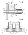
- FIGS. 5 and 6 show a modification of the loading area compared to FIG. 1. Analog parts are provided with the same reference numerals as in FIG. 1, each increased by the number 100.
- the charging housing 128, two charging pistons 130 are guided in opposite directions in the bottom region 129 by force devices 131. Each of the feed pistons 130 is provided with a half-cylinder surface 133.
- two charging chutes 135 are furthermore formed, which are separated from one another by a partition wall 137.
- the feed piston 130 is retracted (FIG. 6 - solid lines)
- the material to be processed falls from the feed chutes 135 into the enlarged spaces between the half-cylinder surfaces 133 and the mixing shaft 114.
Landscapes
- Engineering & Computer Science (AREA)
- Mechanical Engineering (AREA)
- Environmental & Geological Engineering (AREA)
- Processing And Handling Of Plastics And Other Materials For Molding In General (AREA)
Abstract
Description
Die Erfindung betrifft eine Einrichtung zur Herstellung von Formkörpern aus thermoplastischem Werkstoff, insbesondere thermoplastischem Abfallmaterial, umfassend eine zylindrische Durchflußkammer mit einer Materialbeschickungsstelle in einem ersten Endabschnitt und einer Ausflußstelle für thermoplastifiziertes Material in einem zweiten Endabschnitt, eine im wesentlichen konzentrisch innerhalb der zylindrischen Durchflußkammer angeordnete, mit einem Drehantrieb verbundene Mischwelle, welche zusammen mit der Durchflußkammer einen Ringraum definiert und Mischorgane innerhalb des Ringraums trägt, Beheizungsmittel zum Beheizen des jeweils in der Durchflußkammer enthaltenen Materials und Ausschubmittel zum portionsweisen Ausstoßen des thermoplastifizierten Materials durch die Ausflußstelle.The invention relates to a device for the production of molded articles from thermoplastic material, in particular thermoplastic waste material, comprising a cylindrical flow chamber with a material loading point in a first end section and an outflow point for thermoplastic material in a second end section, an essentially concentrically arranged within the cylindrical flow chamber a rotary drive connected mixing shaft, which defines an annular space together with the flow chamber and carries mixing elements within the annular space, heating means for heating the material contained in the flow chamber and ejection means for ejecting the thermoplastic material through the outflow point in portions.
Bei bekannten Einrichtungen dieser Art ist die Mischwelle im wesentlichen auf ihrer ganzen Länge als Schneckenwelle ausgeführt, in Achsrichtung der Durchflußkammer hin- und herbeweglich und an ihrem der Ausflußöffnung zugekehrten Ende mit einem Rückschlagventil versehen. Im Bereich der Ausflußstelle ist eine Dosierkammer gebildet. Im Arbeitsbetrieb wird zunächst das Material unter Plastifizierung in Richtung auf die Dosierkammer gefördert, wobei sich die Schneckenwelle dreht und gleichzeitig in axialer Richtung von der Ausflußstelle zurückweicht. Dabei fließt das thermoplastifizierte Material über das Rückschlagventil hinweg in die Dosierkammer ein. Wenn die Dosierkammer gefüllt ist, bewegt sich die Schneckenwelle in Richtung auf die Ausflußstelle, wobei sich das Rückschlagventil schließt und die in der Dosierkammer enthaltene thermoplastifizierte Masse ausgeschoben wird. Diese bekannte Einrichtung und das vorstehend behandelte Betriebsverfahren dieser Einrichtung haben sich bewährt und in großem Umfang durchgesetzt. Es wird aber hier beanstandet, daß die bekannte Einrichtung insbesondere hinsichtlich des Rückschlagventils aufwendig und störungsanfällig ist. Die Störungsanfälligkeit des Rückschlagventils macht sich insbesondere dann bemerkbar, wenn das zu verarbeitende Material Verunreinigungen enthält, die zu einer Blockierung des Rückschlagventils führen können. Dann besteht insbesondere die Gefahr, daß das Rückschlagventil beim Ausschub der thermoplastifizierten Masse aus der Dosierkammer nicht mehr ordnungsgemäß schließt und somit thermoplastifizierte Masse über das Rückschlagventil zurückfließt. Völlig ungeeignet ist die bekannte Einrichtung dann, wenn es gilt, thermoplastifizierte Abfallmassen zu verarbeiten, die in großem Umfang als Industrieabfälle und als Haushaltsmüll anfallen und die zum einen wertvolle Rohstoffe darstellen und zum anderen aus Gründen des Umweltschutzes aufgearbeitet werden müssen.In known devices of this type, the mixing shaft is designed essentially over its entire length as a worm shaft, can be moved back and forth in the axial direction of the flow chamber and is provided with a check valve at its end facing the outflow opening. A metering chamber is formed in the area of the outflow point. In the working mode, the material is first conveyed towards the metering chamber with plasticization, the worm shaft rotating and at the same time withdrawing in the axial direction from the outflow point. The thermoplastic material flows into the metering chamber via the check valve. When the metering chamber is filled, the screw shaft moves towards the outflow point, the check valve closes and the thermoplastic mass contained in the metering chamber is pushed out. This known device and the operating method of this device discussed above have proven themselves and have been widely adopted. However, it is criticized here that the known device is complex and prone to failure, in particular with regard to the check valve. The check valve's susceptibility to malfunction is particularly noticeable if the material to be processed contains impurities which can lead to the check valve being blocked. Then there is in particular the risk that the check valve no longer closes properly when the thermoplastic mass is ejected from the metering chamber and thus thermoplastic mass flows back via the check valve. The known device is completely unsuitable when it comes to processing thermoplastic waste that accumulates on a large scale as industrial waste and household waste and which on the one hand are valuable raw materials and on the other hand has to be processed for reasons of environmental protection.
Der Erfindung liegt die Aufgabe zugrunde, eine Einrichtung der eingangs bezeichneten Art zu auszubilden, daß sie aus einfachen und kostengünstigen Elementen aufgebaut werden kann und Betriebsstörungen weitgehend vermeidet.The invention has for its object to provide a device of the type mentioned that it can be constructed from simple and inexpensive elements and largely avoids malfunctions.
Zur Lösung dieser Aufgabe wird erfindungsgemäß vorgeschlagen, daß der Ringraum einen in seiner Achsrichtung hin- und herbeweglichen ringkolben aufnimmt, welcher zum Nachfüllen der Durchflußkammer bis hinter die Materialbeschickungsstelle zurückziehbar ist und zum Ausstoßen des thermoplastifizierten Materials in Richtung auf die Ausflußstelle vorschiebbar ist.To achieve this object, it is proposed according to the invention that the annular space receives an annular piston which can be moved back and forth in its axial direction, which can be retracted behind the material loading point for refilling the flow chamber and can be advanced in the direction of the outflow point for expelling the thermoplastic material.
Aus der DE-PS 841 057 ist eine Strangpresse zum Fördern plastischer Massen bekannt, bei welcher in einer zylindrischen Durchflußkammer zentrisch ein erster unverdrehbarer Kolben und in dem Ringraum zwischen dem ersten Kolben und dem Kammermantel ein ebenfalls unverdrehbarer Ringkolben angeordnet ist. Jedem der beiden Kolben ist ein hydraulischer Linearantrieb zugeordnet. Der erste Kolben arbeitet mit einem beweglichen Ventilring an seinem dem Ausfluß der Durchflußkammer zugekehrten Ende zusammen, welcher sich beim Vorschub des ersten Kolbens in Richtung auf den Ausfluß dichtend an das konische Ende des ersten Kolbens anlegt und beim Rückhub des ersten Kolbens von der Konusfläche des ersten Kolbens abhebt, jedoch durch Mitnahmeorgane des ersten Kolbens unter Ventilöffnung mitgenommen wird. Eine Beheizung ist nicht vorgesehen, da offensichtlich die zu verpressende Masse bereits im plastischen Zustand angeboten wird. Bei dieser bekannten Einrichtung treten die gleichen Probleme auf, die beim gattungsbildenden Stand der Technik als Folge des dortigen Rückschlagventils behandelt worden sind.From DE-PS 841 057 an extrusion press for conveying plastic masses is known, in which a first non-rotatable piston is arranged centrally in a cylindrical flow chamber and a likewise non-rotatable annular piston is arranged in the annular space between the first piston and the chamber jacket. A hydraulic linear drive is assigned to each of the two pistons. The first piston cooperates with a movable valve ring at its end facing the outflow of the flow chamber, which sealingly rests against the conical end of the first piston when the first piston is fed in the direction of the outflow, and when the first piston returns from the conical surface of the first Piston lifts up, but is carried along by the driving elements of the first piston under the valve opening. Heating is not provided since the mass to be pressed is obviously already offered in the plastic state. In this known device, the same problems arise that have been dealt with in the generic state of the art as a result of the check valve there.
Aus der DE-PS 1 019 080 ist eine Spritzmaschine zur kontinuierlichen Bearbeitung von schmelzbaren bzw. in der Wärme plastisch verformbaren Kunststoffen behandelt. Dabei ist eine Misch- und Förderwelle in einer zylindrischen Durchflußkammer angeordnet. Diese Misch- und Förderwelle übernimmt allein den Vorschub der plastifizierten Masse in Richtung auf die Ausflußstelle. Ein mit dem Ringkolben des Erfindungsgegenstands vergleichbares Organ ist nicht vorhanden.From DE-PS 1 019 080 a spraying machine for the continuous processing of meltable or thermoplastic materials is treated. A mixing and delivery shaft is arranged in a cylindrical flow chamber. This mixing and conveying shaft takes over the feed of the plasticized mass towards the outflow point. An organ comparable to the ring piston of the subject of the invention is not present.
Es ist ohne weiteres einzusehen, daß bei der erfindungsgemäßen Lösung das konstruktiv besonders aufwendige und gegen Störungen besonders empfindliche Rückschlagventil durch einen leicht herstellbaren und störungsunempfindlichen Ringkolben ersetzt ist.It can easily be seen that in the solution according to the invention the check valve, which is particularly complex in terms of construction and is particularly sensitive to malfunctions, is replaced by an easy-to-manufacture and failure-resistant annular piston.
Die erfindungsgemäße Einrichtung ist zur Verarbeitung üblicher thermoplastischer Rohstoffe in Form von Granulat oder Schnitzeln geeignet. Darüberhinaus und insbesonderere ist die Einrichtung zur Aufarbeitung von Rohstoffen geeignet, die einen erheblichen Anteil von Verunreinigungen besitzen, da das empfindliche Rückschlagventil vermieden ist. Es hat sich gezeigt, daß mit der erfindungsgemäßen Einrichtung auch grobes Abfallmaterial verarbeitet werden kann, welches unschmelzbare Verunreinigungen, insbesondere Metallteile enthält. So ist es z. B. möglich, Joghurtbecherbecher zu verarbeitet, an denen noch Metallfoliendeckel haften, ohne daß Störungen zu erwarten sind.The device according to the invention is suitable for processing conventional thermoplastic raw materials in the form of granules or chips. In addition, and in particular, the device is suitable for processing raw materials which have a considerable proportion of impurities, since the sensitive check valve is avoided. It has been shown that coarse waste material which contains infusible impurities, in particular metal parts, can also be processed with the device according to the invention. So it is z. B. possible to process yoghurt cups to which metal foil lids still adhere without disturbances to be expected.
Wenn eingangs der erfindungsgemäßen Einrichtung die Herstellung von "Formkörpern" zugeschrieben wird, so ist dabei zu beachten, daß der Begriff "Formkörper" in seiner allgemeinsten Bedeutung zu nehmen ist. Formkörper sind zum einen solche Körper, die aufgrund ihrer Form als Endprodukt anzusehen sind. Formkörper sind aber auch Zwischenprodukte in Strang- oder Schnitzelform, die ihrerseits zu Funktionsteilen weiterverarbeitet werden müssen.If the manufacture of “moldings” is initially attributed to the device according to the invention, it should be noted that the term “moldings” is to be taken in its most general meaning. Shaped bodies are on the one hand those bodies which, because of their shape, are to be regarded as the end product. Molded body but are also intermediate products in strand or schnitzel form, which in turn have to be processed into functional parts.
Es empfiehlt sich, den Ringkolben jeweils nur soweit zurückzuziehen, daß er knapp hinter der Materialbeschickungsstelle steht, so daß die durch den Ringkörper zu durchfahrende Strecke insoweit ein Minimum erreicht.It is advisable to retract the ring piston only to such an extent that it is just behind the material loading point so that the distance to be traveled through the ring body reaches a minimum in this respect.
Man kann die Mischwelle in einem ersten, der Materialbeschikkungsstelle benachbarten Bereich als Förderschnecke ausbilden und in einem daran zur Ausflußstelle hin anschließenden zweiten Bereich im wesentlichen glatt ausführen, wobei der Ringkolben dann zumindest in dem zweiten Bereich der Innenumfangsfläche der Durchflußkammer und der Außenumfangsfläche der Mischwelle unmittelbar anliegt oder mit allenfalls geringem Radialabstand. Bei dieser Ausführungsform kann die Förderschnecke für das durch die Beschickungsstelle eingefüllte Rohmaterial während ihrer grundsätzlich der Mischung dienenden Drehung auch eine Förderfunktion übernehmen und das frisch zugefüllte Rohmaterial in Richtung auf die Ausflußstelle fördern. Der Ringkolben wird dann in dem zweiten Bereich wirksam und schiebt das eingefüllte Rohmaterial in Richtung auf die Ausflußstelle, wobei das der Ausflußstelle anliegende Material soweit thermoplastifiziert ist, daß es als eine flüssige bis zähflüssige Masse durch die Ausflußstelle ausgeschoben wird. Die Mischorgane können auf der Mischwelle in einem an den zweiten Bereich zur Ausflußstelle hin anschließenden dritten Bereich angeordnet sein, der von dem Ringkolben nicht erreichbar ist. Auf diese Weise können beliebige Formen von Mischorganen eingesetzt werden, die im Hinblick auf die Mischfunktion optimiert sind und mit dem Ringkolben nicht in Kollision treten.The mixing shaft can be designed as a screw conveyor in a first area adjacent to the material loading point and can be made essentially smooth in a second area adjoining it to the outflow point, the annular piston then directly abutting the inner peripheral surface of the flow chamber and the outer peripheral surface of the mixing shaft at least in the second area or at most with a small radial distance. In this embodiment, the screw conveyor for the raw material filled in by the charging point can also take on a conveying function during its rotation, which basically serves the purpose of mixing, and convey the freshly filled raw material in the direction of the outflow point. The ring piston then becomes effective in the second region and pushes the filled raw material in the direction of the outflow point, the material in contact with the outflow point being thermoplasticized to such an extent that it is pushed out as a liquid to viscous mass through the outflow point. The mixing elements can be arranged on the mixing shaft in a third region which adjoins the second region towards the outflow point and which cannot be reached by the annular piston. In this way, any forms of mixing elements can be used which are optimized with regard to the mixing function and do not collide with the ring piston.
Ist im ersten Bereich eine Förderschnecke vorhanden, so kann man auch in dem ersten Bereich für eine möglichst enge Annäherung des Ringkolbens an die Förderschnecke und gleichzeitig für eine möglichst enge Anlage an der Innenumfangsfläche der Durchflußkammer sorgen. Damit erreicht man, daß die Ausschubwirkung des Ringkolbens bereits in dem ersten Bereich beginnt, bevor der Ringkolben den zweiten Bereich erreicht.If a screw conveyor is present in the first area, the annular piston can be brought as close as possible to the screw conveyor in the first area and at the same time as close as possible to the inner peripheral surface of the flow chamber. It is thus achieved that the pushing-out action of the ring piston begins in the first area before the ring piston reaches the second area.
Die Beheizungsmittel werden unter Mitberücksichtigung der durch mechanische Arbeit erzeugten Wärme vorzugsweise derart angeordnet und bemessen, daß sich beim Ausschub thermoplastifizierten Materials aus der Ausflußstelle in Ausschubrichtung vor dem Ringkolben eine Packung von nicht vollständig thermoplastifiziertem Material als Trennschicht zu dem in Richtung auf die Ausflußstelle hin anschließenden vollständig thermoplastifizierten Material bildet. Diese Packung wird unter den zu erwartenden hohen Drücken hoch komprimiert und im wesentlichen dicht. Die Dichte des komprimierten Materials wird dabei unter Umständen noch dadurch weiter erhöht, daß die die Packung bildenden Teilchen oberflächlich bereits teilweise thermoplastifiziert sind. Diese Packung sorgt dann dafür, daß das vollständig thermoplastifizierte, flüssige bis zähflüssige Material nicht an die Dichtstellen zwischen Ringkolben einerseits und Durchflußzylinder sowie Mischwelle andererseits herantreten kann. Abdichtprobleme sind deshalb weitestgehend vermieden. Die Passung des Ringkolbens gegenüber den anliegenden Flächen der zylindrischen Durchflußkammer und der Mischwelle ist toleranzunempfindlich; eine dichte Anlage im Sinne von flüssigkeitsdicht braucht nicht gewährleistet zu sein. Selbstverständlich muß die Packung dann bis zum Ende des Ringkolbenvorschubs wenigstens teilweise erhalten bleiben.The heating means are preferably arranged and dimensioned, taking into account the heat generated by mechanical work, such that when thermoplastic material is ejected from the outflow point in the ejection direction in front of the ring piston, a package of incompletely thermoplasticized material is provided as a separating layer to the one that follows in the direction of the outflow point thermoplastic material forms. This packing is highly compressed under the high pressures to be expected and is essentially tight. The density of the compressed material may be further increased under certain circumstances in that the particles forming the package are already partially thermoplasticized on the surface. This pack then ensures that the completely thermoplastic, liquid to viscous material cannot reach the sealing points between the annular piston on the one hand and the flow cylinder and the mixing shaft on the other. Sealing problems are therefore largely avoided. The fit of the ring piston with respect to the adjacent surfaces of the cylindrical flow chamber and the mixing shaft is insensitive to tolerances; a tight system in the sense of liquid-tight need not be guaranteed. Of course, the pack must then be at least partially preserved until the end of the ring piston feed.
Um beim beginnenden Vorschub des Ringkolbens, bevor dieser die Materialzuführungsstelle überfahren hat, ein Ausweichen des neu zugeführten Rohmaterials durch die Materialzuführungsstelle zu verhindern, empfiehlt es sich, daß die Materialbeschickungsstelle mit einer Beschickungsvorrichtung ausgeführt ist, welche das Material unter Druck in den ringraum einbringt. Diese Beschickungseinrichtung kann beispielsweise mit einem hin- und hergehenden Beschickungskolben ausgeführt sein, der jedenfalls dann Druck auf das im Ringraum enthaltene Material ausübt, wenn der Ringkolben seinen Vorschub beginnt.In order to prevent the newly supplied raw material from escaping through the material feed point when the ring piston begins to advance before it has passed the material feed point, it is recommended that the material feed point be designed with a feed device which brings the material under pressure into the annular space. This charging device can be designed, for example, with a reciprocating charging piston, which in any case exerts pressure on the material contained in the annular space when the annular piston begins its advance.
Bei einer bevorzugten Ausführungsform der Beschickungseinrichtung ist vorgesehen, daß die Beschickungseinrichtung zwei diametral in Bezug auf die Mischwelle einander gegenüberliegende, in annähernd horizontaler Richtung bewegliche Beschickungskolben umfaßt, deren jeder mit einer der Mischwelle zugekehrten Teilzylinderfläche, insbesondere Halbzylinderfläche ausgestaltet und jeweils in einer Führung am Boden eines Beschickungsgehäuses verschiebbar geführt ist, wobei diese Beschickungskolben zwischen jeweils einer von der Mischwelle zurückgezogenen Aufnahmestellung und einer mischwellennahen Beschickungsstellung verschiebbar sind, in welch letzterer die Teilzylinderflächen einen Teil des Ringraumes bilden. Bei dieser Ausführungsform wird ein großes Beschickungsvolumen durch die beiden Kolben im Bereich der Mischwelle erfaßt und durch gegenseitige Annäherung der beiden Kolben zu einem Ringvolumen um die Mischwelle herum komprimiert. Dieses Ringvolumen wird dann beim nächsten Vorhub des Ringkolbens vorgeschoben.In a preferred embodiment of the charging device, it is provided that the charging device comprises two charging pistons diametrically opposite one another with respect to the mixing shaft and movable in an approximately horizontal direction, each of which is designed with a partial cylinder surface facing the mixing shaft, in particular a half-cylinder surface, and each in a guide on the bottom of a Feed housing is displaceably guided, these feed pistons being displaceable between a receiving position withdrawn from the mixing shaft and a loading position close to the mixing shaft, in which latter the partial cylinder surfaces form part of the annular space. In this embodiment, a large feed volume is detected by the two pistons in the region of the mixing shaft and compressed to an annular volume around the mixing shaft by the two pistons approaching one another. This ring volume is then advanced during the next forward stroke of the ring piston.
Diese Ausführungsform kann im einzelnen so weitergebildet sein, daß das Beschickungsgehäuse beidseits der Mischwelle jeweils einem Beschickungskolben zugeordnet einen Beschickungsschacht aufweist, wobei die beiden Beschickungsschächte durch eine Trennwand voneinander getrennt sind.This embodiment can be further developed in such a way that the charging housing has a charging shaft assigned to a charging piston on each side of the mixing shaft, the two charging chutes being separated from one another by a partition.
Wenngleich diese Beschickungseinrichtung auch in Verbindung mit einer Förderschnecke auf der Mischwelle anwendbar ist, so muß es doch als ein besonderer Vorteil dieser Ausführungsform der Beschickungseinrichtung gelten, daß auf die Förderschnecke der Mischwelle auch verzichtet werden kann.Although this loading device can also be used in connection with a screw conveyor on the mixing shaft, it must However, a particular advantage of this embodiment of the loading device is that the screw conveyor of the mixing shaft can also be dispensed with.
Ist die Mischwelle nicht mehr mit einer Förderschnecke versehen, so besteht die Möglichkeit, daß die Mischwelle während der Beschickung und während des Hin- und Hergangs des Ringkolbens kontinuierlich angetrieben ist. Es sei aber erwähnt, daß der kontinuierliche Antrieb grundsätzlich auch dann möglich ist, wenn auf der Mischwelle eine Förderschnecke angeordnet ist.If the mixing shaft is no longer provided with a screw conveyor, there is the possibility that the mixing shaft is continuously driven during the loading and during the back and forth movement of the ring piston. However, it should be mentioned that the continuous drive is fundamentally also possible if a screw conveyor is arranged on the mixing shaft.
Vor der Ausflußstelle kann eine Ausflußkammer oder Dosierkammer gebildet sein. Das Volumen der pro Ausschubhub des Ringkolbens ausgestoßenen thermoplastifizierte Masse läßt sich durch die Bemessung dieser Kammer und durch die Bemessung der Hublänge des Ringkolbens einstellen. Damit ist eine Anpassung an eine gegebenenfalls nachgeschaltete Form entsprechend deren Formvolumen möglich. Eine angeschlossene Formeinrichtung kann eine Strangformeinrichtung sein, welche beispielsweise ein Profil als Endprodukt erzeugt. Es kann aber auch mit einer Strangformeinrichtung ein Zwischenproduktstrang erzielt werden, der wieder zerhackt werden kann, wobei die durch das Zerhacken gewonnenen Schnitzel in einem späteren Arbeitsgang weiterverarbeitet werden können.An outflow chamber or metering chamber can be formed in front of the outflow point. The volume of the thermoplastic mass expelled per extension stroke of the ring piston can be adjusted by dimensioning this chamber and by dimensioning the stroke length of the ring piston. This makes it possible to adapt to a shape which may be arranged downstream, in accordance with its shape volume. A connected molding device can be a strand molding device which, for example, generates a profile as the end product. However, an intermediate product strand which can be chopped again can also be achieved with a strand shaping device, the chips obtained by the chopping being able to be further processed in a later operation.
Die von der Durchflußkammer bis zur Strangdüse oder Hohlform auftretenden Verengungsstellen müssen natürlich so bemessen werden, daß die Verunreinigungen auch diese Stellen passieren können, sofern man nicht eine Abtrennung der Verunreinigungen in Betracht zieht, worauf noch eingeangen werden wird. Im Bereich der Ausflußstelle kann auch eine Absperrvorrichtung vorgesehen sein. Eine solche Absperrvorrichtung kann ein von außen gesteuerter Ventilschieber sein, der keine Probleme während des Arbeitsbetriebs aufwirft, jedenfalls keine mit einem Rückschlagventil des Standes der Technik vergleichbaren Probleme. Ein solcher Ventilschieber kann jedesmal bei Beginn des Rückhubs des Ringkolbens geschlossen und bei Beginn des Vorschubs wieder geöffnet werden. Es ist aber auch möglich, bei Einrichtungen großer Leistung, die zur Beschickung von kleinvolumigen Formen führen, während eines einzigen Vorhubs die Absperrvorrichtung mehrmals zu schließen, um nacheinander verschiedene Formen im Anschluß an die erfindungsgemäße Einrichtung bringen und füllen zu können.The constriction points occurring from the flow chamber to the extrusion die or hollow mold must of course be dimensioned such that the contaminants can also pass through these locations, provided that separation of the contaminants is not considered, which will be discussed later. A shut-off device can also be provided in the area of the outflow point. Such a shut-off device can be from the outside be controlled valve spool that does not pose any problems during work, in any case no problems comparable to a check valve of the prior art. Such a valve slide can be closed each time at the start of the return stroke of the ring piston and opened again at the start of the feed. However, it is also possible to close the shut-off device several times during a single forward stroke in the case of large-capacity devices which lead to the loading of small-volume molds, in order to be able to bring and fill different molds in succession after the device according to the invention.
Die Erfindung löst auch in vorteilhafter Weise das Problem des Ausscheidens von Verunreinigungen aus der thermoplastifizierten Masse. "Verunreinigungen" ist dabei ganz allgemein zu verstehen. Es können dies unter anderem Metallteilchen oder höher schmelzende Kunststoffteilchen sein. Es sei aber darauf hingewiesen, daß die Abscheidung von Verunreinigungen nicht zwingend erforderlich ist.The invention also advantageously solves the problem of removing contaminants from the thermoplastic mass. "Impurities" is to be understood in a very general sense. These can include metal particles or higher melting plastic particles. However, it should be pointed out that the separation of impurities is not absolutely necessary.
Es ist auch denkbar, daß man an die erfindungsgemäße Einrichtung ohne Abscheidung von Verunreinigungen eine Form zur Herstellung von Formkörpern anschließt, wobei dann die Verunreinigungen in die Formkörper eingehen. Diese Möglichkeit gestattet ein besonders preisgünstiges Arbeiten und wird gewählt, wenn man Formkörper für untergeordnete Zwecke herstellen will, in denen Verunreinigungen weder von der Funktion noch von der mechanischen Festigkeit her störend wirken.It is also conceivable that a mold for the production of moldings is connected to the device according to the invention without the separation of impurities, the impurities then entering the moldings. This possibility allows a particularly inexpensive work and is chosen if you want to produce molded articles for subordinate purposes, in which impurities do not interfere with the function or mechanical strength.
Die erfindungsgemäß weiter vorgeschlagenen Maßnahmen zur Abscheidung der Verunreinigungen sind insbesondere in Verbindung mit der soweit beschriebenen Einrichtung geeignet, sind aber auch in anderem Zusammenhang einsetzbar und sollen selbständigen Patentschutz genießen.The measures proposed further according to the invention for separating the impurities are particularly suitable in connection with the device described so far, but can also be used in another context and are intended to enjoy independent patent protection.
Voraussetzung für die erfindungsgemäße Einrichtung zur Abscheidung der Verunreinigungen ist wiederum eine Durchfluß kammer mit einer Materialbeschickungsstelle und einer Ausflußstelle für das thermoplastifizierte Material, wobei wiederum Beheizungsmittel, Mischorgane und Ausschubmittel vorgesehen sind. Der Durchfluß durch die Durchflußkammer kann dabei schubweise oder kontinuierlich erfolgen.A flow is again a prerequisite for the device according to the invention for separating the contaminants chamber with a material loading point and an outflow point for the thermoplastic material, heating means, mixing elements and ejecting means in turn being provided. The flow through the flow chamber can be batch or continuous.
Zur Abscheidung der Verunreinigungen ist vorgesehen, daß vor der Ausflußstelle ein Sieb angeordnet ist, daß vor dem Sieb ein Nebenabfluß für Grobbestandteile vorgesehen ist und daß an der stromoberseitigen Fläche des Siebs mindestens ein die Grobbestandteile in den Nebenabfluß fördernder Schaber angeordnet ist. Bei einer solchen Ausbildung tritt das thermoplastifizierte flüssige bis zähflüssige Material durch das Sieb hindurch, während die Verunreinigungen durch den Nebenabfluß abgeführt werden. Grundsätzlich könnte der Nebenabfluß durch ein Absperrventil absperrbar sein, so daß bei Auftreten des Ausschubdrucks in der Durchflußkammer das Absperrventil abgesperrt werden kann und damit kein unkontrollierter Abfluß von brauchbarer thermoplastifizierter Masse durch den Nebenabfluß eintritt. Es hat sich aber gezeigt, daß das durch den Nebenabfluß abfließende Grobgut eine Konsistenz besitzt, welche das Weglassen eines Absperrventils im engeren Sinne erlaubt, wenn man nämlich in dem Nebenabfluß eine Klemmstelle vorsieht, welche jeweils bei Auftreten eines Ausschubdrucks in der Durchflußkammer einen durch den Nebenabfluß abfließenden Strang von Grobbestandteilen klemmt. Durch den Nebenabfluß erhält man einen harten Strang, der beispielsweise bei der Verarbeitung von Joghurtbechern mit Metallfoliendeckel im wesentlichen aus Metallfolienschnitzeln besteht, die durch einen geringen Rest von thermoplastischer Masse aneinander gebunden sind. Dieses Strangmaterial kann entweder zur Rückgewinnung der Verunreinigungen, insbesondere des Metalls, weiterverarbeitet oder auch auf einer Müllhalde raumsparend gelagert werden. Um der Klemmstelle ein unbewegliches Festhalten des Grobmaterialstrangs zu gestatten, kann man vor der Klemmstelle eine Kühlstrecke an dem Nebenabfluß vorsehen, so daß dieser Strang an der Klemmstelle bereits hart ist.To separate the impurities, it is provided that a sieve is arranged in front of the outflow point, that a secondary outflow for coarse constituents is provided in front of the sieve, and that at least one scraper conveying the coarse constituents into the secondary outflow is arranged on the upstream surface of the sieve. With such a design, the thermoplasticized liquid to viscous material passes through the sieve, while the impurities are discharged through the secondary drain. In principle, the secondary drain could be shut off by a shut-off valve, so that when the discharge pressure occurs in the flow chamber, the shut-off valve can be shut off and thus no uncontrolled drainage of usable thermoplastic mass occurs through the secondary drain. It has been shown, however, that the coarse material flowing out through the secondary drain has a consistency which allows a shut-off valve to be omitted in the narrower sense, namely if a clamping point is provided in the secondary drain, which in each case, when a discharge pressure occurs in the flow chamber, leads through the secondary drain draining strand of coarse constituents stuck. The secondary drain gives a hard strand which, for example when processing yogurt cups with a metal foil lid, essentially consists of metal foil chips which are bound to one another by a small remnant of thermoplastic material. This strand material can either be further processed for the recovery of the impurities, in particular the metal, or it can also be stored in a space-saving manner on a waste dump. An immobile grip around the clamping point to allow the coarse material strand, you can provide a cooling section at the secondary drain before the nip, so that this strand is already hard at the nip.
Da sich die Verunreinigungen an der stromaufwärtigen Fläche des Sieb sammeln, empfiehlt es sich, daß der Schaber unmittelbar an dem Sieb entlangschabt und insbesondere, daß der Schaber in einer Führungsrinne der stromaufwärtigen Fläche des Siebs geführt ist, von welcher mindestens ein Teil der Sieböffnungen ausgeht.Since the contaminants collect on the upstream surface of the sieve, it is recommended that the scraper scrape directly along the sieve and in particular that the scraper is guided in a guide groove of the upstream surface of the sieve, from which at least a part of the sieve openings originates.
Um das vor dem Schaber hergeschobene Abfallgut möglichst unmittelbar in dem Nebenabfluß zu fördern, empfiehlt es sich, daß der Schaber in Flucht mit dem Nebenabfluß geführt ist. Dabei wird eine besonders vollständige Abführung des Grobmaterials insbesondere dann erreicht, wenn der Schaber in Vollzug seiner Schaberbewegung in den Nebenabfluß eintaucht. Taucht der Schaber in den Nebenabfluß ein, so ist nicht auszuschließen, daß er auch größere Mengen brauchbaren Thermoplasts in den Nebenabfluß drängt, welcher durchaus auch durch das Sieb hindurchtreten könnte. Um diese Verluste möglichst gering zu halten, wird vorgeschlagen, daß an dem Schaber siebende Rückflußausnehmungen vorgesehen sind, welche beim Eintauchen des Schabers in den Nebenabfluß einen Rückfluß von thermoplastifizierter Begleitmasse der Grobbestandteile in Richtung zur Durchflußkammer gestatten. Durch diese Rückflußausnehmungen wird dann die thermoplastifizierte Begleitmasse zurückgedrängt, und zwar umso mehr, je höher der Ausschubwiderstand des durch den Nebenabfluß austretenden Strangs ist. Dieser Abflußwiderstand kann gegebenenfalls durch Regulierung der Klemmstelle eingestellt werden. Eine einfache Gestaltung für die Rückflußausnehmungen ergibt sich dadurch, daß diese von Nuten an dem in den Nebenabfluß eintauchenden Ende des Schabers gebildet sind.In order to convey the waste material pushed in front of the scraper as directly as possible in the secondary drain, it is recommended that the scraper be aligned with the secondary drain. A particularly complete removal of the coarse material is achieved in particular when the scraper dips into the secondary drain in the course of its scraper movement. If the scraper is immersed in the secondary drain, it cannot be ruled out that it will also force large quantities of usable thermoplastic into the secondary drain, which could also pass through the sieve. In order to keep these losses as low as possible, it is proposed that on the scraper sieving reflux recesses are provided which, when the scraper is immersed in the secondary outflow, allow a backflow of thermoplastic accompanying mass of the coarse components in the direction of the flow chamber. The thermoplastic accompanying mass is then pushed back by these reflux recesses, and the more so, the higher the resistance to ejection of the strand emerging through the secondary outflow. This discharge resistance can be adjusted if necessary by regulating the clamping point. A simple design for the reflux recesses results from the fact that these are formed by grooves on the end of the scraper which plunges into the secondary outflow.
Da eine Querdrift von Verunreinigungen über die stromaufwärtige Fläche des Siebs kaum zu erwarten ist, empfiehlt es sich, daß im wesentlichen sämtliche Durchflußöffnungen des Siebs durch den Schaber bestreichbar sind.Since a cross drift of contaminants over the upstream surface of the sieve can hardly be expected, it is recommended that essentially all of the flow openings of the sieve can be brushed by the scraper.
Aus Gründen einer einfacheren räumlichen Unterbringung kann es vorteilhaft sein, daß mehrere, vorzugsweise zwei, Schaber vorgesehen sind, wobei die Schaber bevorzugt längs zueinander paralleler Bewegungsbahnen geführt sind.For reasons of simpler spatial accommodation, it may be advantageous to provide a plurality, preferably two, of scraper, the scraper preferably being guided along mutually parallel trajectories.
Das Vorhandensein von zwei oder mehr Schabern erlaubt auch eine besonders vorteilhafte Arbeitsweise, bei der die Schaber derart im Gegentakt geführt sind, daß beim Ausstoßen der thermoplastifizierten Masse jeweils ein Teil der Sieböffnungen frei ist. Dann kann man die Schaber unter Umständen ohne Abstimmung zur Vorschubbewegung in der Durchflußkammer bewegen, weil ja immer ein Teil der Sieböffnungen zur Verfügung steht. Ein solcher Aufbau ist deshalb insbesondere dann von Interesse, wenn eine kontinuierliche Reinigung gewünscht wird.The presence of two or more scrapers also allows a particularly advantageous mode of operation, in which the scrapers are guided in a push-pull manner in such a way that a part of the screen openings is free when the thermoplastic mass is expelled. The scraper can then be moved in the flow chamber under certain circumstances without coordination with the feed movement, because part of the screen openings is always available. Such a structure is therefore of particular interest when continuous cleaning is desired.
Eine bevorzugte Ausführungsform für die Form des Schabers ergibt sich dadurch, daß der Schaber von einer prismatischen oder zylindrischen Stange gebildet ist, welche in einer entsprechenden, mit dem Nebenabfluß fluchtenden Führung geführt ist. Bevorzugt ist diese Ausführung deshalb, weil bei ihr eine Rückwärtsmitnahme von Grobmaterial durch den Schaber ausgeschlossen ist, wenn sich der Schaber von dem Nebenabfluß zurückbewegt.A preferred embodiment for the shape of the scraper results from the fact that the scraper is formed by a prismatic or cylindrical rod which is guided in a corresponding guide which is aligned with the secondary drain. This embodiment is preferred because it prevents the coarse material from being carried backwards by the scraper when the scraper moves back from the secondary drain.
Um dem Problem einer ständigen Öffnung wenigstens eines Teils der Sieböffnungen Rechnung zu tragen, ist es auch möglich, daß die Stange an ihrem freien Ende einen in den Nebenabfluß eintauchenden Schaberkopf und rückwärts dieses Schaberkopfes einen verringerten Querschnitt aufweist. Bei dieser Ausführungs form ist allerdings eine Rückwärtsmitnahme der Grobverunreinigungen nicht ausgeschlossen, so daß die Verweilzeit der Grobvernreinigungen vor dem Sieb - im Durchschnitt gesehen - vergrößert wird.In order to take into account the problem of a constant opening of at least some of the sieve openings, it is also possible for the rod to have a scraper head immersed in the secondary drain at its free end and a reduced cross section to the rear of this scraper head. In this execution form, however, a backward take of the coarse contaminants is not excluded, so that the residence time of the coarse contaminants before the sieve - seen on average - is increased.
Die beiliegenden Figuren erläutern die Erfindung anhand eines Ausführungsbeispiels. Es stellen dar:
- Fig. 1 eine Gesamtansicht einer erfindungsgemäßen Einrichtung;
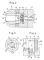
- Fig. 2 einen Schnitt nach Linie II-II der Fig. 1;
- Fig. 3 einen Schnitt nach Linie III-III der Fig. 1 und
- Fig. 4 eine Vergrößerung in dem Bereich IV der Fig. 1.
- Fig. 5 eine Teilabwandlung zu Fig. 1 und
- Fig. 6 einen Schnitt nach Linie VI-VI der Fig. 5.
- 1 shows an overall view of a device according to the invention;
- Fig. 2 is a section along line II-II of Fig. 1;
- Fig. 3 is a section along line III-III of Fig. 1 and
- 4 is an enlargement in the area IV of FIG. 1st
- Fig. 5 shows a partial modification to Fig. 1 and
- 6 shows a section along line VI-VI of FIG. 5th
In Fig. 1 ist ein Zylinder mit 10 bezeichnet. Innerhalb dieses Zylinders ist eine Durchflußkammer 12 begrenzt. Konzentrisch innerhalb der Durchflußkammer 12 ist eine Mischwelle 14 angeordnet, die an ihrem in der Fig. 1 linken Ende durch einen Drehantrieb 16 angetrieben ist. An ihrem rechten Ende ist die Mischwelle 14 in einem Lagerring 18 gelagert, welcher seinerseits in dem Zylinder 10 durch eine Lochplatte oder ein Speichenkreuz (nicht eingezeichnet) festgehalten ist. Zwischen der Mischwelle 14 und dem Zylinder 10 ist ein Ringraum 20 eingeschlossen. Die Mischwelle ist in einem ersten Bereich A als Schneckenwelle 14a ausgebildet. In einem zweiten Bereich B ist die Mischwelle glatt.In Fig. 1, a cylinder is designated 10. A
In einem dritten Bereich C ist die Mischwelle 14 mit Mischorganen 22 versehen, die - wie aus Fig. 3 zu ersehen - im Beispielsfall von Flossen gebildet sind, welche in Längsnuten 24 der Mischwelle 14 eingesetzt sind. Im Bereich A ist an dem Zylinder eine Materialbeschickungsstelle 26 angebracht. Diese umfaßt einen Beschickungszylinder 28 und einen in dem Beschickungszylinder geführten Beschickungskolben 30. An den Beschickungszylinder schließt sich ein Materialzuführungsrohr an.In a third area C, the mixing
Am rechten Ende des Zylinders 10 sind in Sandwich-Bauweise Blöcke oder Platten 34, 36 und 38 angeflanscht. Innerhalb der von diesen Blöcken oder Platten gebildeten Baugruppe ist eine Ausflußkammer 40 gebildet, welche durch ein Sieb 42 abgeschlossen ist. Auf der rechten Seite des Siebs ist eine Sammelkammer 44 in dem Block 36 gebildet, an welche sich ein Absperrventil 46 in dem Block 38 anschließt. Von der Sammelkammer 44 führt ein Kanal 48 über das Absperrventil 46 zu einer zweiteiligen Form 50. Die zweiteilige Form 50 ist von der Platte 38 lösbar bzw. dicht an diese Platte anpreßbar.At the right end of the
Die Mischwelle 14 ist von einem Ringkolben 52 umgeben, welcher durch Kraftgeräte 54 hin- und herverschiebbar ist. Der Zylinder 10 ist von ringförmigen Heizkörpern 56 umgeben.The mixing
Die soweit beschriebene Vorrichtung arbeitet wie folgt: Bei zurückgezogenem Ringkolben 52 und nach oben zurückgezogenem Beschickungskolben 30 wird Rohmaterial durch das Rohr 32 in den Beschickungszylinder 28 eingeführt. Der Beschickungskolben 30 schiebt das Rohmaterial nach unten nach. Die Förderschnecke 14a fördert das Rohmaterial in dem Ringraum 20 nach rechts durch die Bereiche A, B und C. Durch die Heizkörper 56 wird das Rohmaterial in Fortschreitrichtung nach rechts zunehmend plastifiziert. Durch die Mischorgane 22 wird das plastifizierte Rohmaterial in Fortschreitrichtung nach rechts zunehmend homogenisiert. Es bildet sich in dem durch horizontale Striche angedeuteten Teilbereich 58 eine Füllung von flüssigem bis zähflüssigem Material, welche auch die Ausflußkammer 40 füllt. In dem Teilbereich 60 ist das Rohmaterial noch in derjenigen Konsistenz vorhanden, in der es zugeführt wird. In dem Bereich 62 liegt eine Übergangskonsistenz vor. Das Rohmaterial ist bereits teilweise plastifiziert, insbesondere an der Oberfläche der Rohmaterialteilchen.The device described so far operates as follows: With the annular piston 52 retracted and the
Wenn nun der Ringkolben 52 nach rechts in die strichpunktiert gezeichnete Lage, d. h. in Pfeilrichtung 64 vorgeschoben wird, so wird zunächst die Beschickungsstelle 26 verschlossen. Das Rohmaterial in dem Teilbereich 60 und insbesondere in dem Teilbereich 62 wird komprimiert. Das flüssige bis zähflüssige thermoplastische Material im Teilbereich 58 und in der Ausflußkammer 40 wird durch das Sieb 42 hindurchgepreßt und fließt über die Sammelkammer 44, das Absperrventil und den Kanal 48 in die Form 50 ein. Dann wird der Ringkolben 52 durch die Kraftgeräte 54 wieder zurückgezogen. Damit ist der Anlaufbetrieb beendet. Im stationären Betrieb enthält der Teilbereich 58, zumindest aber die Ausflußkammer 40 ständig thermoplastifiziertes Material. In dem Teilbereich 62 ist ständig dicht gepacktes, teilweise plastifiziertes Material vorhanden und im Teilbereich 60 befindet sich ständig ein Rest von nicht thermoplastifiziertem Rohmaterial. Nach jedem Rückhub des Ringkolbens 52 wird erneut Material durch die Beschickungsstelle 26 eingeführt und durch die Förderschnecke 14a nach rechts vorgeschoben. Danach beginnt wieder der Vorschub des Ringkolbens 52. Das in Vorschubrichtung vordere Ende des Ringkolbens 52 ist von dem voll thermoplastifizierten Material im Teilbereich 58 ständig durch eine Packung 62 von teilweise plastifiziertem Material getrennt, so daß die Dichtflächen zwischen der Mischwelle 14 in deren glattem Bereich B und dem Ringkolben 52 und auch die Dichtflächen zwischen dem Ringkolben 52 und dem Zylinder 10 für das voll thermoplastifizierte Material im wesentlichen unzugänglich sind. Vor jedem Vorschubhub wird auch im stationären Betrieb durch die Drehung der Mischwelle 14 eine innige Durchmischung herbeigeführt. Der Ringkolben 52 liegt auch an der Schnecke der Schneckenwelle 14a eng an, so daß vom Beginn des Vorschubs des Ringkolbens 52 an eine Mitnahmebewegung auf das Material übertragen wird, spätestens dann, wenn der Ringkolben 52 das durch die Schneckenwelle 14a nach rechts geförderte Material im Teilbereich 60 erreicht hat.If the annular piston 52 is now pushed to the right into the position shown in broken lines, ie in the direction of the
Wie aus Fig. 1, 2 und 4 ersichtlich, sind in dem Block 36 Schaber 70 geführt. Diese Schaber sind in Form von zylindrischen Stäben ausgeführt, welche durch jeweils eine Bohrung 72 in den Block 36 eingeführt sind und in die Kammer 40 eintauchen können. Die Schaber liegen mit einem Teil ihres Umfangs in Rinnen 74 der Siebplatte 42, von denen die Siebbohrungen 42a ausgehen. Wenn die Schaber 70 die in Fig. 1 gezeigte obere Stellung innerhalb der Durchflußkammer 40 einnehmen, so sind die Sieböffnungen 42a alle offen. In dem Block 36 sind ferner in Flucht mit den Schabern 70 Nebenabflußbohrungen 76 angeordnet. An diese Nebenabflußbohrungen 76 schließen sich, wie aus Fig. 1 zu ersehen, Nebenabflußrohre 78 an. Die Nebenabflußrohre 78 sind von einem Kühlkörper 80 umgeben. An den Kühlkörper 80 schließt sich nach unten eine Klemmstelle 82 an. Wenn ein Schaber 70 nach unten geht, ausgehend von der Stellung der Fig. 1 in Richtung auf die Stellung gemäß Fig. 4, so werden die Verunreinigungen, die sich in der jeweiligen Rinne 74 angesammelt haben, von dem Schaber 70 nach unten in den Bereich der Nebenabflußbohrung 76 geschoben. Im stationären Zustand schließt sich an die Nebenabflußbohrung 76 bereits ein Strang 84 von Grobmaterial an, welcher durch die Klemmstelle 82 klemmbar ist. Die Abwärtsbewegung des Schabers 70 findet statt, während der Ringkolben 52 stillsteht, so daß in der Ausflußkammer 40 ein geringer Druck herrscht. Diesem Druck kann der Strang 84 unter der Wirkung der Klemmstelle 82, 84 jedenfalls so lange standhalten, bis der Schaber 70 - wie in Fig. 4 gezeigt - in die Nebenabflußbohrung 76 einge taucht ist. Dann wird der Strang 84 durch den Schaber 70 nach unten geschoben, wobei der Vorschubwiderstand durch entsprechende Einstellung der Klemmstelle 82 eingestellt werden kann. Bei diesem Vorschub des Strangs 84 strömt thermoplastifiziertes Material, welches in die Nebenabflußbohrung 76 gelangt ist, in Pfeilrichtung 86 zurück in die Ausflußkammer 40. Der Strang 84 hat deshalb einen sehr geringen Gehalt an brauchbarem thermoplastischem Material und besteht im wesentlichen nur aus Abfällen.1, 2 and 4,
Da - wie in Fig. 2 dargestellt - zwei Schaber 70 vorhanden sind, können diese Schaber 70 im Gegentakt arbeiten, so daß unabhängig von dem Hubzyklus des Ringkolbens 52 ständig ein Teil der Abflußbohrungen 42a des Siebs 36 geöffnet ist und der Abfluß des thermoplastifizierten gereinigten Materials durch das Sieb 42 ständig gewährleistet ist. Da sich die Verunreinigungen unter der Wirkung der Strömung in der Ausflußkammer 40 vorwiegend in den Rinnen 74 ansammeln, ist eine ständige und vollständige Absonderung der Verunreinigungen gewährleistet. Da die Schaber 70 als Stäbe von gleichbleibendem Querschnitt ausgebildet sind, ist kein Aufwärtstransport von Verunreinigungen möglich.Since - as shown in FIG. 2 - there are two
Der Hub des Ringkolbens 52 kann so eingestellt werden, daß bei jedem Vorschubhub eine Form 50 gerade gefüllt wird. Es ist aber auch möglich, während des Vorschubhubs des Ringkolbens 52 den Ausfluß der thermoplastifizierten Masse durch den Kanal 48 mittels des Absperrventils 46 intermittierend abzusperren, so daß nacheinander während eines Vorschubhubs verschiedene Formen gefüllt werden können. Weiter ist es möglich, eine Form durch mehrere aufeinanderfolgende Vorschubhübe des Ringkolbens 52 zu füllen, dann nämlich, wenn die Leistung der Einrichtung im Verhältnis zum Formvolumen der Form 50 zu klein ist. Auch dann kann das Absperrventil 46 zwischen aufeinanderfolgenden Vorschubmitteln des Ringkolbens 52 abgesperrt werden.The stroke of the annular piston 52 can be adjusted so that a
In den Figuren 5 und 6 ist eine Abwandlung des Beschickungsbereichs gegenüber Fig. 1 dargestellt. Analoge Teile sind mit gleichen Bezugszeichen versehen wie in Fig. 1, jeweils vermehrt um die Zahl 100. In dem Beschickungsgehäuse 128 sind im Bodenbereich 129 zwei Beschickungskolben 130 durch Kraftgeräte 131 gegenläufig geführt. Jeder der Beschickungskolben 130 ist mit einer Halbzylinderfläche 133 versehen. In dem Beschickungsgehäuse sind ferner zwei Beschickungsschächte 135 ausgebildet, die durch eine Trennwand 137 voneinander getrennt sind. Bei zurückgezogenem Beschikkungskolben 130 (Fig. 6 - ausgezogene Linien) fällt das zu verarbeitende Material aus den Beschickungsschächten 135 in die vergrößerten Zwischenräume zwischen den Halbzylinderflächen 133 und der Mischwelle 114. Danach gehen die Beschickungskolben 130 in die strichpunktiert eingezeichneten Positionen der Fig. 6 über, so daß die Halbzylinderflächen 133 dann einen geschlossenen Ringraum um die Mischwelle 114 bilden und damit die Durchflußkammer 112 glatt durchgehend ergänzen. In diesem Zustand führt der Ringkolben 152 seinen Vorhub aus und gibt das vorher zu einer Ringpackung komprimierte Material in den Bereich der Beheizung 156 und der Mischorgange 122. Eine Schneckenwelle ist dabei - wie gezeichnet - nicht mehr erforderlich, könnte aber immer noch vorhanden sein. Die Mischwelle 114 ist kontinuierlich angetrieben, auch während des Rückhubs des Ringkolbens 152. Wie bei der zuvor beschriebenen Ausführungsform bleibt auch hier zwischen dem thermoplastifizierten Material und dem rechten Ende des Ringkolbens 152 stets eine Packung von nicht vollständig thermoplastifiziertem Material, welche eine Dichtungsfunktion übernimmt. Im übrigen entspricht die Ausführungsform nach den Fig. 5 und 6 derjenigen nach den Fig. 1 bis 4.FIGS. 5 and 6 show a modification of the loading area compared to FIG. 1. Analog parts are provided with the same reference numerals as in FIG. 1, each increased by the number 100. In the charging
Claims (33)
Applications Claiming Priority (2)
| Application Number | Priority Date | Filing Date | Title |
|---|---|---|---|
| DE19883802719 DE3802719A1 (en) | 1988-01-29 | 1988-01-29 | DEVICE FOR PRODUCING MOLDED BODIES FROM THERMOPLASTIC MATERIAL |
| DE3802719 | 1988-01-29 |
Publications (2)
| Publication Number | Publication Date |
|---|---|
| EP0326036A2 true EP0326036A2 (en) | 1989-08-02 |
| EP0326036A3 EP0326036A3 (en) | 1991-10-23 |
Family
ID=6346276
Family Applications (1)
| Application Number | Title | Priority Date | Filing Date |
|---|---|---|---|
| EP19890100986 Withdrawn EP0326036A3 (en) | 1988-01-29 | 1989-01-20 | Apparatus for the manufacture of moulded thermoplastic bodies |
Country Status (2)
| Country | Link |
|---|---|
| EP (1) | EP0326036A3 (en) |
| DE (1) | DE3802719A1 (en) |
Cited By (2)
| Publication number | Priority date | Publication date | Assignee | Title |
|---|---|---|---|---|
| EP0467842A1 (en) * | 1990-07-17 | 1992-01-22 | GPW MACCHINE S.a.S. di GIUSEPPE PONZIELLI & C. | Method of and apparatus for transferring and compacting particulate solids |
| US5356280A (en) * | 1991-11-27 | 1994-10-18 | Gpw Machine S.A.S. Di Giuseppe Ponzielli & C. | Pump for particulate solids |
Families Citing this family (1)
| Publication number | Priority date | Publication date | Assignee | Title |
|---|---|---|---|---|
| DE202006018977U1 (en) * | 2006-12-15 | 2008-04-17 | Petersen Service Gmbh | cleaning device |
Citations (8)
| Publication number | Priority date | Publication date | Assignee | Title |
|---|---|---|---|---|
| US1770396A (en) * | 1926-07-16 | 1930-07-15 | Joseph C Fuller | Machine for molding tubular material and method of producing same |
| US2485523A (en) * | 1943-07-21 | 1949-10-18 | Hpm Dev Corp | Hydraulic injection of plastics as a continuous strip |
| FR1195939A (en) * | 1957-06-13 | 1959-11-20 | Battenfeld Maschfab | Device for plasticizing and injecting thermoplastic plastics |
| US3029471A (en) * | 1959-10-14 | 1962-04-17 | Owens Illinois Glass Co | Method and apparatus for making plastic articles |
| US3319297A (en) * | 1964-07-17 | 1967-05-16 | Goodrich Co B F | Injection molding machine |
| GB2005555A (en) * | 1977-09-14 | 1979-04-25 | Nihon Repro Machine Kogyo Kk | Device for removing foreignmaterial for use in a machine for reclaming synthetic resin from scrap |
| US4177234A (en) * | 1977-10-05 | 1979-12-04 | Metals & Plastics, Inc. | Method and apparatus for cleaning thermoplastic materials |
| US4225547A (en) * | 1975-12-15 | 1980-09-30 | Sumitomo Electric Industries, Ltd. | Extrusion process of polytetrafluoroethylene tubing materials and apparatus therefor |
Family Cites Families (2)
| Publication number | Priority date | Publication date | Assignee | Title |
|---|---|---|---|---|
| DE841057C (en) * | 1949-06-16 | 1952-06-13 | Friedrich Banz | Extrusion press |
| US3225963A (en) * | 1964-12-07 | 1965-12-28 | Vasken F Arpajian | Hopper apparatus and method |
-
1988
- 1988-01-29 DE DE19883802719 patent/DE3802719A1/en not_active Withdrawn
-
1989
- 1989-01-20 EP EP19890100986 patent/EP0326036A3/en not_active Withdrawn
Patent Citations (8)
| Publication number | Priority date | Publication date | Assignee | Title |
|---|---|---|---|---|
| US1770396A (en) * | 1926-07-16 | 1930-07-15 | Joseph C Fuller | Machine for molding tubular material and method of producing same |
| US2485523A (en) * | 1943-07-21 | 1949-10-18 | Hpm Dev Corp | Hydraulic injection of plastics as a continuous strip |
| FR1195939A (en) * | 1957-06-13 | 1959-11-20 | Battenfeld Maschfab | Device for plasticizing and injecting thermoplastic plastics |
| US3029471A (en) * | 1959-10-14 | 1962-04-17 | Owens Illinois Glass Co | Method and apparatus for making plastic articles |
| US3319297A (en) * | 1964-07-17 | 1967-05-16 | Goodrich Co B F | Injection molding machine |
| US4225547A (en) * | 1975-12-15 | 1980-09-30 | Sumitomo Electric Industries, Ltd. | Extrusion process of polytetrafluoroethylene tubing materials and apparatus therefor |
| GB2005555A (en) * | 1977-09-14 | 1979-04-25 | Nihon Repro Machine Kogyo Kk | Device for removing foreignmaterial for use in a machine for reclaming synthetic resin from scrap |
| US4177234A (en) * | 1977-10-05 | 1979-12-04 | Metals & Plastics, Inc. | Method and apparatus for cleaning thermoplastic materials |
Non-Patent Citations (2)
| Title |
|---|
| PATENT ABSTRACTS OF JAPAN, Band 3, Nr. 63 (C-47), 30 Mai 1979; & JP-A-54 036 371 (KOBE SEIKOSHO K.K.) 17-03-1979. * |
| PATENT ABSTRACTS OF JAPAN, Band 4, Nr. 171 (M-44)[653], 26 November 1980; & JP-A-55 123 440 (MATSUSHITA DENKO K.K.) 22-09-1980. * |
Cited By (3)
| Publication number | Priority date | Publication date | Assignee | Title |
|---|---|---|---|---|
| EP0467842A1 (en) * | 1990-07-17 | 1992-01-22 | GPW MACCHINE S.a.S. di GIUSEPPE PONZIELLI & C. | Method of and apparatus for transferring and compacting particulate solids |
| US5223199A (en) * | 1990-07-17 | 1993-06-29 | Gpw Macchine S.A.S. Di Giuseppe Ponzielli & C. Of Via Vallone | Method of and apparatus for pumping particulate solids |
| US5356280A (en) * | 1991-11-27 | 1994-10-18 | Gpw Machine S.A.S. Di Giuseppe Ponzielli & C. | Pump for particulate solids |
Also Published As
| Publication number | Publication date |
|---|---|
| EP0326036A3 (en) | 1991-10-23 |
| DE3802719A1 (en) | 1989-08-10 |
Similar Documents
| Publication | Publication Date | Title |
|---|---|---|
| DE1296336C2 (en) | DEVICE FOR MANUFACTURING TUBES BY PRESSING AND WELDING TUBE HEADS WITH PREFABRICATED TUBES MADE OF THERMOPLASTIC PLASTIC | |
| DE102013114570B4 (en) | Injector for filling a mold with plastic particles | |
| EP0078064B1 (en) | Apparatus for separating materials of different consistency | |
| DE2622001A1 (en) | METHOD AND DEVICE FOR MANUFACTURING FOAMED PLASTIC | |
| EP0925904A1 (en) | Method and device for changing the screen of a filtering apparatus | |
| DE2355458B1 (en) | Device for the injection molding of plastic particles with a smooth surface and a porous core | |
| WO2022135855A1 (en) | Discharge technology for plastic filters | |
| DE69502853T2 (en) | Process for the injection molding of curved hollow bodies | |
| EP1631435B1 (en) | Plant for the preparation of materials | |
| DE2135635A1 (en) | Method and device for impact injection molding of objects from plastic masses | |
| EP0326036A2 (en) | Apparatus for the manufacture of moulded thermoplastic bodies | |
| DE2128791A1 (en) | Method and device for compression molding of plastics | |
| EP0107778A2 (en) | Method and apparatus for the treatment of plastifiable material | |
| EP0204133B1 (en) | Method for making objects of thermoplastic material by injection moulding | |
| DE3113515A1 (en) | Dewatering and compacting press for waste substances | |
| EP0485909B1 (en) | Device for compacting small containers for liquids especially incorrectly-filled beer cans or similar compressible items | |
| DE1529962B1 (en) | Injection molding machine | |
| DE2406569B2 (en) | METHOD FOR EXTRUDING OR INJECTION MOLDING THERMOPLASTIC PLASTICS AND DEVICE FOR CARRYING OUT THE METHOD | |
| EP0564690A1 (en) | Method and apparatus for automatically manufacturing plastic articles, particularly recycled plastics | |
| EP0656251A1 (en) | Method and apparatus for manufacturing objects from thermoplastic material by injection moulding | |
| DE2733245C3 (en) | Plastic injection molding machine with several injection cylinders and rotating injection molds | |
| DE19849797A1 (en) | Injector for feeding thermoplastic material into a tool | |
| EP0160782A1 (en) | Apparatus for separating matter of different consistency | |
| DE2312957B2 (en) | Injection molding machine for injection molding of elastomers | |
| DE3239030A1 (en) | Apparatus for separating materials of different consistency |
Legal Events
| Date | Code | Title | Description |
|---|---|---|---|
| PUAI | Public reference made under article 153(3) epc to a published international application that has entered the european phase |
Free format text: ORIGINAL CODE: 0009012 |
|
| AK | Designated contracting states |
Kind code of ref document: A2 Designated state(s): AT BE CH DE ES FR GB GR IT LI LU NL SE |
|
| PUAL | Search report despatched |
Free format text: ORIGINAL CODE: 0009013 |
|
| AK | Designated contracting states |
Kind code of ref document: A3 Designated state(s): AT BE CH DE ES FR GB GR IT LI LU NL SE |
|
| 17P | Request for examination filed |
Effective date: 19920326 |
|
| 17Q | First examination report despatched |
Effective date: 19921001 |
|
| STAA | Information on the status of an ep patent application or granted ep patent |
Free format text: STATUS: THE APPLICATION IS DEEMED TO BE WITHDRAWN |
|
| 18D | Application deemed to be withdrawn |
Effective date: 19930414 |