EP0325181B1 - A method of manufacturing a polysilicon emitter and a polysilicon gate using the same etch of polysilicon on a thin gate oxide - Google Patents
A method of manufacturing a polysilicon emitter and a polysilicon gate using the same etch of polysilicon on a thin gate oxide Download PDFInfo
- Publication number
- EP0325181B1 EP0325181B1 EP19890100610 EP89100610A EP0325181B1 EP 0325181 B1 EP0325181 B1 EP 0325181B1 EP 19890100610 EP19890100610 EP 19890100610 EP 89100610 A EP89100610 A EP 89100610A EP 0325181 B1 EP0325181 B1 EP 0325181B1
- Authority
- EP
- European Patent Office
- Prior art keywords
- region
- layer
- polysilicon
- emitter
- bipolar
- Prior art date
- Legal status (The legal status is an assumption and is not a legal conclusion. Google has not performed a legal analysis and makes no representation as to the accuracy of the status listed.)
- Expired - Lifetime
Links
Images


Classifications
-
- H—ELECTRICITY
- H01—ELECTRIC ELEMENTS
- H01L—SEMICONDUCTOR DEVICES NOT COVERED BY CLASS H10
- H01L27/00—Devices consisting of a plurality of semiconductor or other solid-state components formed in or on a common substrate
- H01L27/02—Devices consisting of a plurality of semiconductor or other solid-state components formed in or on a common substrate including semiconductor components specially adapted for rectifying, oscillating, amplifying or switching and having at least one potential-jump barrier or surface barrier; including integrated passive circuit elements with at least one potential-jump barrier or surface barrier
- H01L27/04—Devices consisting of a plurality of semiconductor or other solid-state components formed in or on a common substrate including semiconductor components specially adapted for rectifying, oscillating, amplifying or switching and having at least one potential-jump barrier or surface barrier; including integrated passive circuit elements with at least one potential-jump barrier or surface barrier the substrate being a semiconductor body
- H01L27/06—Devices consisting of a plurality of semiconductor or other solid-state components formed in or on a common substrate including semiconductor components specially adapted for rectifying, oscillating, amplifying or switching and having at least one potential-jump barrier or surface barrier; including integrated passive circuit elements with at least one potential-jump barrier or surface barrier the substrate being a semiconductor body including a plurality of individual components in a non-repetitive configuration
- H01L27/0611—Devices consisting of a plurality of semiconductor or other solid-state components formed in or on a common substrate including semiconductor components specially adapted for rectifying, oscillating, amplifying or switching and having at least one potential-jump barrier or surface barrier; including integrated passive circuit elements with at least one potential-jump barrier or surface barrier the substrate being a semiconductor body including a plurality of individual components in a non-repetitive configuration integrated circuits having a two-dimensional layout of components without a common active region
- H01L27/0617—Devices consisting of a plurality of semiconductor or other solid-state components formed in or on a common substrate including semiconductor components specially adapted for rectifying, oscillating, amplifying or switching and having at least one potential-jump barrier or surface barrier; including integrated passive circuit elements with at least one potential-jump barrier or surface barrier the substrate being a semiconductor body including a plurality of individual components in a non-repetitive configuration integrated circuits having a two-dimensional layout of components without a common active region comprising components of the field-effect type
- H01L27/0623—Devices consisting of a plurality of semiconductor or other solid-state components formed in or on a common substrate including semiconductor components specially adapted for rectifying, oscillating, amplifying or switching and having at least one potential-jump barrier or surface barrier; including integrated passive circuit elements with at least one potential-jump barrier or surface barrier the substrate being a semiconductor body including a plurality of individual components in a non-repetitive configuration integrated circuits having a two-dimensional layout of components without a common active region comprising components of the field-effect type in combination with bipolar transistors
-
- H—ELECTRICITY
- H01—ELECTRIC ELEMENTS
- H01L—SEMICONDUCTOR DEVICES NOT COVERED BY CLASS H10
- H01L21/00—Processes or apparatus adapted for the manufacture or treatment of semiconductor or solid state devices or of parts thereof
- H01L21/02—Manufacture or treatment of semiconductor devices or of parts thereof
- H01L21/04—Manufacture or treatment of semiconductor devices or of parts thereof the devices having at least one potential-jump barrier or surface barrier, e.g. PN junction, depletion layer or carrier concentration layer
- H01L21/18—Manufacture or treatment of semiconductor devices or of parts thereof the devices having at least one potential-jump barrier or surface barrier, e.g. PN junction, depletion layer or carrier concentration layer the devices having semiconductor bodies comprising elements of Group IV of the Periodic System or AIIIBV compounds with or without impurities, e.g. doping materials
- H01L21/28—Manufacture of electrodes on semiconductor bodies using processes or apparatus not provided for in groups H01L21/20 - H01L21/268
- H01L21/28008—Making conductor-insulator-semiconductor electrodes
- H01L21/28017—Making conductor-insulator-semiconductor electrodes the insulator being formed after the semiconductor body, the semiconductor being silicon
- H01L21/28026—Making conductor-insulator-semiconductor electrodes the insulator being formed after the semiconductor body, the semiconductor being silicon characterised by the conductor
- H01L21/28035—Making conductor-insulator-semiconductor electrodes the insulator being formed after the semiconductor body, the semiconductor being silicon characterised by the conductor the final conductor layer next to the insulator being silicon, e.g. polysilicon, with or without impurities
-
- H—ELECTRICITY
- H01—ELECTRIC ELEMENTS
- H01L—SEMICONDUCTOR DEVICES NOT COVERED BY CLASS H10
- H01L21/00—Processes or apparatus adapted for the manufacture or treatment of semiconductor or solid state devices or of parts thereof
- H01L21/02—Manufacture or treatment of semiconductor devices or of parts thereof
- H01L21/04—Manufacture or treatment of semiconductor devices or of parts thereof the devices having at least one potential-jump barrier or surface barrier, e.g. PN junction, depletion layer or carrier concentration layer
- H01L21/18—Manufacture or treatment of semiconductor devices or of parts thereof the devices having at least one potential-jump barrier or surface barrier, e.g. PN junction, depletion layer or carrier concentration layer the devices having semiconductor bodies comprising elements of Group IV of the Periodic System or AIIIBV compounds with or without impurities, e.g. doping materials
- H01L21/30—Treatment of semiconductor bodies using processes or apparatus not provided for in groups H01L21/20 - H01L21/26
- H01L21/31—Treatment of semiconductor bodies using processes or apparatus not provided for in groups H01L21/20 - H01L21/26 to form insulating layers thereon, e.g. for masking or by using photolithographic techniques; After treatment of these layers; Selection of materials for these layers
- H01L21/3105—After-treatment
- H01L21/311—Etching the insulating layers by chemical or physical means
- H01L21/31105—Etching inorganic layers
- H01L21/31111—Etching inorganic layers by chemical means
- H01L21/31116—Etching inorganic layers by chemical means by dry-etching
-
- H—ELECTRICITY
- H01—ELECTRIC ELEMENTS
- H01L—SEMICONDUCTOR DEVICES NOT COVERED BY CLASS H10
- H01L21/00—Processes or apparatus adapted for the manufacture or treatment of semiconductor or solid state devices or of parts thereof
- H01L21/70—Manufacture or treatment of devices consisting of a plurality of solid state components formed in or on a common substrate or of parts thereof; Manufacture of integrated circuit devices or of parts thereof
- H01L21/77—Manufacture or treatment of devices consisting of a plurality of solid state components or integrated circuits formed in, or on, a common substrate
- H01L21/78—Manufacture or treatment of devices consisting of a plurality of solid state components or integrated circuits formed in, or on, a common substrate with subsequent division of the substrate into plural individual devices
- H01L21/82—Manufacture or treatment of devices consisting of a plurality of solid state components or integrated circuits formed in, or on, a common substrate with subsequent division of the substrate into plural individual devices to produce devices, e.g. integrated circuits, each consisting of a plurality of components
- H01L21/822—Manufacture or treatment of devices consisting of a plurality of solid state components or integrated circuits formed in, or on, a common substrate with subsequent division of the substrate into plural individual devices to produce devices, e.g. integrated circuits, each consisting of a plurality of components the substrate being a semiconductor, using silicon technology
- H01L21/8248—Combination of bipolar and field-effect technology
- H01L21/8249—Bipolar and MOS technology
Landscapes
- Engineering & Computer Science (AREA)
- Power Engineering (AREA)
- Microelectronics & Electronic Packaging (AREA)
- General Physics & Mathematics (AREA)
- Condensed Matter Physics & Semiconductors (AREA)
- Computer Hardware Design (AREA)
- Physics & Mathematics (AREA)
- Manufacturing & Machinery (AREA)
- Chemical & Material Sciences (AREA)
- Chemical Kinetics & Catalysis (AREA)
- General Chemical & Material Sciences (AREA)
- Inorganic Chemistry (AREA)
- Metal-Oxide And Bipolar Metal-Oxide Semiconductor Integrated Circuits (AREA)
- Bipolar Transistors (AREA)
- Bipolar Integrated Circuits (AREA)
Description
- This invention relates to semiconductor devices and, more particularly, to the simultaneous formation of bipolar and metal oxide semiconductor (MOS) devices on the same silicon substrate.
- Methods for the fabrication of bipolar devices and MOS devices are known. Typically, bipolar devices are fabricated separately from MOS devices because of the structural differences between the two types of devices. This means that a circuit which uses both bipolar and MOS devices must be constructed using discrete chips, which increases the size and cost of the product. EP-A-0 196 757 discloses a method defined by the preamble of
claim 1. - If bipolar and MOS devices are to be combined, an integrated approach to device fabrication must be devised. However, applying the fabrication techniques used for one type of device to another type of device typically degrades the performance of the other device. For example, a common method for making electrical contact to a silicon substrate in a bipolar transistor involves the use of a layer of polysilicon deposited on the surface of the substrate. Electrical contact to the silicon substrate is made through this layer of polysilicon. The resulting structure is termed a "buried contact." However, the polysilicon/silicon interface layer increases the series resistance through the device. This is insignificant in bipolar devices, because the base of bipolar devices has small current flowing through it, and bipolar devices have intrinsically high resistances. However, the source and drain in MOS devices carry all of the current, so any increase in series resistance significantly affects performance of the devices. Series resistance can be improved by increasing the contact area, but with a resulting decrease in yield. Finally, the thin gate oxide layer used in MOS devices is subject to contamination and mechanical damage when subjected to bipolar fabrication methods.
- The present invention is directed to a method of making bipolar and MOS devices simultaneously using a single fabrication process. The process according to
Claim 1 of the present invention employs the use of buried contacts without significantly affecting the performance of the MOS devices, and a very thin gate oxide layer may be used in the MOS devices without jeopardizing the integrity or performance of the devices. - In one embodiment of the present invention, a silicon substrate is divided into bipolar and MOS regions. A thin layer of gate oxide then is thermally grown on the silicon substrate. A thin layer of polysilicon is deposited on the gate oxide layer to protect the gate oxide layer during subsequent processing, and then both the thin polysilicon layer and the gate oxide layer are removed from the bipolar region where the emitter is to be formed. To maintain the integrity of the gate oxide layer, the photoresist mask used during the polysilicon etch is retained during the gate oxide etch, and the gate oxide is etched in a buffered oxide etch solution. A thick layer of polysilicon then is deposited on the bipolar and MOS regions of the silicon substrate, and the substrate is masked for forming the emitter and gates of the bipolar and MOS devices, respectively, After the emitter and gate locations are masked, the polysilicon is simultaneously etched from the bipolar and MOS regions for forming the respective emitter and gates. Since the polysilicon over the area where the emitter is formed is thinner than the polysilicon over the MOS region, the silicon substrate surrounding the emitter is etched for forming the emitter island. The areas for the base and collector of the bipolar device and the source and drain of the MOS devices are selectively masked during etching of the polysilicon for providing buried contacts to these regions, if desired.
- These and other features and advantages of the invention will become apparent to those skilled in the art upon a reading of the following detailed description of the invention, which should be taken in conjunction with the accompanying drawings.
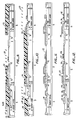
- Figs. 1-16 illustrate the steps of forming a combination bipolar/CMOS device according to the present invention.
- Fig. 1 shows a
silicon substrate 4 after having undergone preliminary processing according to conventional methods. For example,silicon substrate 4 has been processed to form abipolar region 8, anNMOS region 12, and aPMOS region 16.Bipolar region 8 is intended to be used for forming an NPN transistor, whereasNMOS region 12 is intended to be used for forming an N-channel MOS device, andPMOS region 16 is intended to be used for forming a P-channel MOS device. -
Silicon substrate 4 is formed of a P-type material. Consequently,bipolar region 8 andPMOS region 16 have formed therein arsenic doped N+ buriedlayers layers layers wells substrate 4 according to well known techniques. N+ buriedlayers wells - Disposed above
substrate 4 are a layer ofsilicon dioxide 36 and a layer ofsilicon nitride 40.Silicon dioxide layer 36 preferably is thermally grown on the surface ofsubstrate 4 by placingsubstrate 4 in an oxygen or steam, preferably steam, environment at a temperature of approximately 900°C for 30 minutes.Silicon dioxide layer 36 has a thickness in the range of from approximately 350 angstroms to 450 angstroms, preferably 400 angstroms (10 Å = 1 nm = 10⁻³ »m).Silicon nitride layer 40 may be deposited on top ofsilicon dioxide layer 36 by chemical vapor deposition (CVD).Silicon nitride layer 40 has a thickness in the range of from approximately 1500 angstroms to approximately 1700 angstroms, preferably 1600 angstroms. - Finally, a layer of
photoresist 44 is deposited onsilicon nitride layer 40 through a blanket coating, preferably by spinning, to a thickness of approximately 1.5»m. Thephotoresist layer 44 is subjected to a pattern exposure so that development of the photoresist produces portions ofphotoresist layer 44, as shown in Fig. 2. These remaining portions ofphotoresist layer 44 function as a mask to enable etching of thelayer 40 of silicon nitride in the areas not protected by the remaining portions ofphotoresist layer 44. This etching preferably is a dry etch with a plasma, such as SF₆. This produces the structure illustrated in Fig. 2. - After
silicon nitride layer 40 is etched, semi-recessed isolation oxide (SROX)regions SROX regions bipolar region 8 is electrically isolated fromNMOS region 12 bySROX region 52, andNMOS region 12 is electrically isolated fromPMOS region 16 by SROXregion 56. SROXregion 48 separatesbipolar region 8 into acollector region 64 and a base/emitter region 68. The remaining portions ofphotoresist layer 44 are removed by a solvent or oxygen plasma, for example. - After formation of the
SROX regions silicon nitride layer 40 andsilicon dioxide layer 36 are removed to produce the structure shown in Fig. 4. The portions ofsilicon nitride layer 40 may be removed by wet etching in orthophosphoric acid, andsilicon dioxide layer 36 may be removed by wet etching in hydroflouric acid. - As shown in Fig. 5, the next step is to form a thin layer of
silicon dioxide 70 on the exposed surfaces ofsubstrate 4.Silicon dioxide layer 70 preferably is grown in the same manner assilicon dioxide layer 36, and it has a thickness in the range of from approximately 150 angstroms to 300 angstroms, preferably 170 angstroms. This range has been found by experimentation to be critical in order to avoid contamination and mechanical damage during subsequent processing. Next, a thinpolycrystalline silicon layer 72 is deposited as a blanket coating over thesilicon dioxide layer 70 and theSROX regions polycrystalline silicon layer 72 is deposited by CVD, and it has a thickness of from approximately 500 angstroms to 1000 angstroms, preferably 700 angstroms. This thickness ofpolycrystalline silicon layer 72 has been found by experimentation to be critical to protectsilicon dioxide layer 70 during subsequent processing. - Next, as shown in Fig. 6, a
photoresist layer 76 is deposited as a blanket coating overpolycrystalline silicon layer 72 in the same manner asphotoresist layer 44. Afterphotoresist layer 76 is deposited and developed,openings 80 are formed over base/emitter region 68 and over those regions where buried contacts to the silicon substrate are desired. Two such regions are shown. With the remaining portions ofphotoresist layer 76 functioning as a mask, the exposed sections ofpolycrystalline silicon layer 72 are removed by a dry etch. The dry etch may be performed with a plasma, such as SF₆. Then, the exposed portions ofgate oxide layer 70 are ion-implanted with a P-type impurity, preferably boron, with an energy of 40 KeV to a concentration of approximately 1 x 10¹⁸ atoms/cm³. This P-type implant forms theinitial base region 84 in N-well 28 ofbipolar region 8 and thesource contact region 85 inPMOS region 16. On the other hand, the P-type implant has a negligible effect on the P-type substrate beneath the exposed region inNMOS region 12. - Next, as shown in Fig. 7, the exposed portions of
gate oxide layer 70 are removed through a buffered oxide etch while maintainingphotoresist layer 76 as a mask.Photoresist layer 76 then is removed, and a relatively thickpolycrystalline silicon layer 74 is deposited as a blanket coating by CVD over the remaining portions ofpolycrystalline silicon layer 72 and the exposed areas ofsilicon substrate 4.Polycrystalline silicon layer 74 is substantially thicker thanpolycrystalline silicon layer 72, and preferably has a thickness of from approximately 2200 angstroms to 2800 angstroms, preferably 2500 angstroms. Next, a layer ofphotoresist 77 is deposited and developed to form openings 88 over base/emitter region 68, where an emitter is to be formed, and overNMOS region 12. Polycrystalline silicon layers 72 and 74 then are doped by ion implantation to reduce their resistivity. Preferably, an N-type impurity, such as arsenic, is used, and the ions are implanted with an energy of 80 KeV to a concentration of from approximately 1 x 10¹⁵ to 1 x 10¹⁶ atoms/cm³. This is to make the conductivity of the exposed polysilicon layers as high as possible to function as a conductor. The remaining portions ofphotoresist layer 77 are removed, and the structure is then annealed at a temperature of from approximately 900°C to 950°C for approximately 30 minutes in a nitrogen atmosphere. This causes diffusion to expand theinitial base region 84 andP+ region 85 and to formN+ region 92. - Next, a shown in Fig. 8, a
photoresist layer 96 is deposited overpolysilicon layer 74.Photoresist layer 96 is developed to expose all areas ofpolysilicon layer 74, except over aregion 100 which will form the emitter of the bipolar device, over aregion 104 which will form the gate of the NMOS device, over aregion 106 which will form the gate of the PMOS device, and over the regions ofpolysilicon layer 74 where buried contacts to the silicon substrate are to be made, e.g., overSROX region 52. The exposed portions ofpolysilicon layer 74 then are etched by a plasma, such as SF₆, until the exposed portions of polysilicon are removed. Since some areas of polysilicon comprisepolysilicon layers only polysilicon layer 74, portions ofsubstrate 4 not protected bygate oxide layer 70 are etched to a depth approximately equal to that of thepolysilicon layer 72. This occurs in base/emitter region 68 and forms anemitter island 108. Consequently, the thickness ofpolysilicon layers regions polysilicon layer 74 andemitter island 108 inregion 100. - Next, as shown in Fig. 9,
photoresist layer 96 is removed and aphotoresist layer 110 is deposited oversubstrate 4 everywhere exceptcollector region 64 ofbipolar region 8 andNMOS region 12. Then, a lightly doped drain (LDD) implant is performed with phosphorous ions on the exposed regions at an implantation energy of 40 KeV to a concentration of from approximately 1 x 10¹³ to 1 x 10¹⁴ atoms/cm³. - Next, as shown in Fig. 10,
photoresist layer 110 is removed and a photoresist layer 114 is deposited oversubstrate 4. Photoresist layer 114 then is developed to formopenings 118 over base/emitter region 68 andPMOS region 16. Then, a P-type LDD implant is performed, preferably with boron difluoride at an implantation energy of 50 KeV to a concentration of from approximately 1 x 10¹³ to 1 x 10¹⁴, preferably 5 x 10¹³ atoms/cm³. Thereafter, photoresist layer 114 is removed. - Next, as shown in Fig. 11, a conformal silicon dioxide layer is deposited by CVD over the entire surface of
substrate 4 to a thickness of from approximately 1500 to 4000 angstroms, preferably 2000 angstroms.Silicon dioxide layer 122 then is subjected to an LTO densification by heating at approximately 900°C for approximately 15 minutes. - Then, as shown in Fig. 12,
silicon dioxide layer 122 is subjected to an anisotropic etch, preferably in a plasma comprising He·C₂F₆·CHF₃ to formspacers - In the next step, shown in Fig. 13, a
photoresist mask 144, similar tophotoresist mask 110, is deposited and developed to exposecollector region 64 andNMOS region 12. An N-type ion implant then is performed, preferably with arsenic, at an implantation energy of 100 KeV to a concentration of approximately 5 x 10¹⁵ atoms/cm³ for forming the source and drain regions of the NMOS device and the collector of the bipolar device. Afterwards,substrate 4 is annealed at a temperature of 900°C for approximately 30 minutes to formN+ collector 145, inbipolar region 8, and N+ source 146 (which merges with N+ region 92) andN+ drain 147 inNMOS region 12. - Similarly, as shown in Fig. 14, a photoresist layer 150 is deposited and developed to form an
opening 154 overPMOS region 16, and then a P-type ion implant is performed with boron difluoride at an implantation energy of 50 KeV to a concentration of approximately 3 x 10¹⁵ atoms/cm³ for creating the source and drain of the PMOS device. Then, as shown in Fig. 15, photoresist layer 150 is removed and a final blanket, unmasked P-type implant with BF₂ at an implantation energy of 50 KeV to a concentration of 1 x 10¹⁴ atoms/cm³ is performed for forming the extrinsic base of the bipolar device.Substrate 4 then is annealed at a temperature of 900° for approximately 40 minutes to form base 155 (which merges with region 84), inbipolar region 8, and P+ source 156 (which merges with P+ region 85) andP+ drain 157 inPMOS region 16. - Finally, as shown in Fig. 16, the exposed silicon and polysilicon regions are silicided using well known techniques to form silicide layers 173. The
substrate 4 is covered with aplanarizing layer 174 of deposited oxide using well known techniques, such as LTO.Planarizing layer 174 then is etched, andmetal contacts 178 are made to the conductive regions also using well known techniques. - While the above is a complete description of a preferred embodiment of the present invention, various modifications may be employed. For example, techniques may be used to construct a single MOS device without the bipolar devices, and the base, collector, and emitter of bipolar devices formed and the source, drain, and gate of MOS devices formed may be selectively electrically contacted with buried contacts, as desired.
Claims (7)
- A method of making a polysilicon emitter and a polysilicon gate in a semiconductor device, comprising the steps of:
growing a thin layer (70) of gate oxide on emitter and gate regions of a silicon substrate (4),
removing the gate oxide layer from the emitter region of the silicon substrate,
depositing a thick polysilicon layer (74) on the emitter and gate regions of the silicon substrate,
masking the emitter and gate regions for defining a respective emitter and gate,
simultaneously etching portions of the polysilicon from the emitter and gate regions for forming the respective emitter and gate, characterized in that prior to the gate oxide removing step, a thin layer (72) of polysilicon is deposited on the gate oxide layer and is subsequently removed from the emitter region, and that upon said simultaneous etching step the etch in the emitter region extends into the substrate by an amount corresponding to the thickness of said thin polysilicon layer. - The method according to claim 1 wherein the polysilicon layer removing step comprises the steps of:
depositing a photoresist layer (76) as a blanket coating above the thin polysilicon layer;
developing the photoresist layer for forming an opening (80) in the photoresist layer for exposing the portion of the polysilicon layer above the emitter region; and
etching the exposed portion of the polysilicon layer for exposing the portion of the gate oxide layer above the emitter region. - The method according to claim 2 wherein the gate oxide layer removing step comprises the steps of:
retaining the photoresist layer (76); and
etching the exposed portion of the gate oxide layer (70) in a buffered oxide etching solution. - The method according to claim 3 wherein the gate oxide growing step comprises the step of:
growing a layer (70) of silicon dioxide on emitter and gate regions of the silicon substrate, the silicon dioxide having a thickness in the range of from approximately 15 nm (150 angstroms) to approximately 30 nm (300 angstroms). - The method according to claim 4 wherein the thin polysilicon layer depositing step comprises the step of depositing a polysilicon layer (72) to a thickness of from approximately 50 nm (500 angstroms) to approximately 100 nm (1000 angstroms).
- The method according to claim 5 further comprising the steps of:
depositing a conformal oxide layer (122) as a blanket coating over the silicon substrate (4); and
anisotropically etching the conformal layer from the bipolar region and from the MOS region. - The method according to one of claims 1 to 6, comprising the steps:
forming a bipolar region (8) in said silicon substrate for a bipolar device, the bipolar region having a first region (64), termed a collector region, and a second region (68), the first and second regions being separated by a first fields oxide region (48);
forming a MOS region (12, 16) in the silicon substrate for a MOS device, the MOS region being separate from the bipolar region by a second field oxide region (52);
forming said thin gate oxide layer (70) on the bipolar region and on the MOS region;
forming said thin polysilicon layer on the bipolar region and on the MOS region;
removing the thin polysilicon layer from the second region;
removing the thin gate oxide layer from the second region;
depositing said thick polysilicon layer on the bipolar region and on the MOS region;
masking a portion of the second region for forming an emitter;
masking a portion of the MOS region for forming a gate;
simultaneously etching the polysilicon from the bipolar region and from the MOS region other than from the masked portions of the bipolar region and the MOS region;
removing the thin gate oxide layer from the collector region;
doping the collector region and the MOS region to a first conductivity type;
doping the second region to a conductivity type opposite the conductivity type of the collector region;
depositing a conformal oxide layer (122) on the bipolar region and on the MOS region; and
anisotropically etching the conformal layer from the bipolar region and from the MOS region.
Applications Claiming Priority (2)
| Application Number | Priority Date | Filing Date | Title |
|---|---|---|---|
| US14507688A | 1988-01-19 | 1988-01-19 | |
| US145076 | 1988-01-19 |
Publications (3)
| Publication Number | Publication Date |
|---|---|
| EP0325181A2 EP0325181A2 (en) | 1989-07-26 |
| EP0325181A3 EP0325181A3 (en) | 1990-10-10 |
| EP0325181B1 true EP0325181B1 (en) | 1995-04-05 |
Family
ID=22511513
Family Applications (1)
| Application Number | Title | Priority Date | Filing Date |
|---|---|---|---|
| EP19890100610 Expired - Lifetime EP0325181B1 (en) | 1988-01-19 | 1989-01-14 | A method of manufacturing a polysilicon emitter and a polysilicon gate using the same etch of polysilicon on a thin gate oxide |
Country Status (4)
| Country | Link |
|---|---|
| EP (1) | EP0325181B1 (en) |
| JP (2) | JP2895845B2 (en) |
| CA (1) | CA1296111C (en) |
| DE (1) | DE68921995T2 (en) |
Families Citing this family (10)
| Publication number | Priority date | Publication date | Assignee | Title |
|---|---|---|---|---|
| JPS62274471A (en) * | 1986-05-23 | 1987-11-28 | Fanuc Ltd | Picture processor |
| JPH03198371A (en) * | 1989-12-27 | 1991-08-29 | Oki Electric Ind Co Ltd | Manufacture of semiconductor device |
| IT1248534B (en) * | 1991-06-24 | 1995-01-19 | Sgs Thomson Microelectronics | PROCEDURE FOR THE CREATION OF CALIBRATION STRUCTURES PARTICULARLY FOR THE CALIBRATION OF MACHINES FOR MEASURING THE MISALIGNMENT IN INTEGRATED CIRCUITS IN GENERAL. |
| KR930008018B1 (en) * | 1991-06-27 | 1993-08-25 | 삼성전자 주식회사 | Bicmos device and manufacturing method of the same |
| JPH05226589A (en) * | 1992-02-17 | 1993-09-03 | Mitsubishi Electric Corp | C-bicmos semiconductor device and manufacture thereof |
| FR2702307B1 (en) * | 1993-03-05 | 1995-08-18 | Itt Ind Gmbh Deutsche | Method for manufacturing a monolithic integrated circuit with at least one CMOS field effect transistor and a bipolar npn transistor. |
| US5411900A (en) * | 1993-03-05 | 1995-05-02 | Deutsche Itt Industries, Gmbh | Method of fabricating a monolithic integrated circuit with at least one CMOS field-effect transistor and one NPN bipolar transistor |
| DE4319437C1 (en) * | 1993-03-05 | 1994-05-19 | Itt Ind Gmbh Deutsche | BiCMOS monolithic IC mfr. - avoids need for epitaxial and buried layers |
| DE19523536A1 (en) * | 1994-07-12 | 1996-01-18 | Siemens Ag | CMOS FET and complementary bipolar transistor mfr. |
| US6448124B1 (en) * | 1999-11-12 | 2002-09-10 | International Business Machines Corporation | Method for epitaxial bipolar BiCMOS |
Family Cites Families (7)
| Publication number | Priority date | Publication date | Assignee | Title |
|---|---|---|---|---|
| JPS6072255A (en) * | 1983-09-28 | 1985-04-24 | Toshiba Corp | Semiconductor ic device and manufacture thereof |
| GB8507624D0 (en) * | 1985-03-23 | 1985-05-01 | Standard Telephones Cables Ltd | Semiconductor devices |
| JPH0628296B2 (en) * | 1985-10-17 | 1994-04-13 | 日本電気株式会社 | Method for manufacturing semiconductor device |
| JPS6298663A (en) * | 1985-10-24 | 1987-05-08 | Nec Corp | Semiconductor integrated circuit device |
| US4735911A (en) * | 1985-12-17 | 1988-04-05 | Siemens Aktiengesellschaft | Process for the simultaneous production of bipolar and complementary MOS transistors on a common silicon substrate |
| DE3680520D1 (en) * | 1986-03-22 | 1991-08-29 | Itt Ind Gmbh Deutsche | METHOD FOR PRODUCING A MONOLITHICALLY INTEGRATED CIRCUIT WITH AT LEAST ONE BIPOLAR PLANAR TRANSISTOR. |
| JPS62239563A (en) * | 1986-04-11 | 1987-10-20 | Nec Corp | Manufacture of semiconductor device |
-
1989
- 1989-01-14 EP EP19890100610 patent/EP0325181B1/en not_active Expired - Lifetime
- 1989-01-14 DE DE1989621995 patent/DE68921995T2/en not_active Expired - Fee Related
- 1989-01-18 CA CA000588500A patent/CA1296111C/en not_active Expired - Fee Related
- 1989-01-19 JP JP1008734A patent/JP2895845B2/en not_active Expired - Fee Related
-
1998
- 1998-10-05 JP JP28286898A patent/JP3165118B2/en not_active Expired - Lifetime
Also Published As
| Publication number | Publication date |
|---|---|
| JP3165118B2 (en) | 2001-05-14 |
| EP0325181A3 (en) | 1990-10-10 |
| DE68921995D1 (en) | 1995-05-11 |
| JP2895845B2 (en) | 1999-05-24 |
| CA1296111C (en) | 1992-02-18 |
| JPH11191597A (en) | 1999-07-13 |
| JPH023964A (en) | 1990-01-09 |
| EP0325181A2 (en) | 1989-07-26 |
| DE68921995T2 (en) | 1995-12-07 |
Similar Documents
| Publication | Publication Date | Title |
|---|---|---|
| US4752589A (en) | Process for the production of bipolar transistors and complementary MOS transistors on a common silicon substrate | |
| US5424572A (en) | Spacer formation in a semiconductor structure | |
| US5668024A (en) | CMOS device structure with reduced risk of salicide bridging and reduced resistance via use of a ultra shallow, junction extension, ion implantation process | |
| US5082796A (en) | Use of polysilicon layer for local interconnect in a CMOS or BiCMOS technology incorporating sidewall spacers | |
| US5001081A (en) | Method of manufacturing a polysilicon emitter and a polysilicon gate using the same etch of polysilicon on a thin gate oxide | |
| US5336625A (en) | BiCMOS process with low base recombination current bipolar transistors | |
| EP0296627A2 (en) | Method for manufacturing a semiconductor device | |
| US5079177A (en) | Process for fabricating high performance bicmos circuits | |
| JPH04226064A (en) | Interconnection body for semiconductor device use its manufacture | |
| EP0325181B1 (en) | A method of manufacturing a polysilicon emitter and a polysilicon gate using the same etch of polysilicon on a thin gate oxide | |
| US5328860A (en) | Method of manufacturing a semiconductor device | |
| JPH09232445A (en) | Semiconductor device and its manufacture | |
| US5179031A (en) | Method of manufacturing a polysilicon emitter and a polysilicon gate using the same etch of polysilicon on a thin gate oxide | |
| US5348896A (en) | Method for fabricating a BiCMOS device | |
| US5081518A (en) | Use of a polysilicon layer for local interconnect in a CMOS or BICMOS technology incorporating sidewall spacers | |
| JPH0645343A (en) | Semiconductor device provided with borosilicate glass spacer and its manufacture | |
| US5124817A (en) | Polysilicon emitter and a polysilicon gate using the same etch of polysilicon on a thin gate oxide | |
| US5158900A (en) | Method of separately fabricating a base/emitter structure of a BiCMOS device | |
| EP0763256B1 (en) | METHOD OF MANUFACTURING A SEMICONDUCTOR DEVICE WITH BiCMOS CIRCUIT | |
| EP0398247A2 (en) | Semidonductor device and method of manufacturing the same | |
| US5904519A (en) | Method of manufacturing Bi-CMOS | |
| KR970005147B1 (en) | Semiconductor memory device | |
| KR930008898B1 (en) | Manufacturing method of semiconductor device | |
| JPH08102505A (en) | Fabrication of semiconductor device | |
| JP2889246B2 (en) | Semiconductor device |
Legal Events
| Date | Code | Title | Description |
|---|---|---|---|
| PUAI | Public reference made under article 153(3) epc to a published international application that has entered the european phase |
Free format text: ORIGINAL CODE: 0009012 |
|
| AK | Designated contracting states |
Kind code of ref document: A2 Designated state(s): DE FR GB IT NL |
|
| PUAL | Search report despatched |
Free format text: ORIGINAL CODE: 0009013 |
|
| AK | Designated contracting states |
Kind code of ref document: A3 Designated state(s): DE FR GB IT NL |
|
| 17P | Request for examination filed |
Effective date: 19901220 |
|
| 17Q | First examination report despatched |
Effective date: 19921023 |
|
| GRAA | (expected) grant |
Free format text: ORIGINAL CODE: 0009210 |
|
| AK | Designated contracting states |
Kind code of ref document: B1 Designated state(s): DE FR GB IT NL |
|
| PG25 | Lapsed in a contracting state [announced via postgrant information from national office to epo] |
Ref country code: IT Free format text: LAPSE BECAUSE OF FAILURE TO SUBMIT A TRANSLATION OF THE DESCRIPTION OR TO PAY THE FEE WITHIN THE PRE;WARNING: LAPSES OF ITALIAN PATENTS WITH EFFECTIVE DATE BEFORE 2007 MAY HAVE OCCURRED AT ANY TIME BEFORE 2007. THE CORRECT EFFECTIVE DATE MAY BE DIFFERENT FROM THE ONE RECORDED.SCRIBED TIME-LIMIT Effective date: 19950405 Ref country code: NL Free format text: LAPSE BECAUSE OF FAILURE TO SUBMIT A TRANSLATION OF THE DESCRIPTION OR TO PAY THE FEE WITHIN THE PRESCRIBED TIME-LIMIT Effective date: 19950405 Ref country code: FR Effective date: 19950405 |
|
| REF | Corresponds to: |
Ref document number: 68921995 Country of ref document: DE Date of ref document: 19950511 |
|
| EN | Fr: translation not filed | ||
| NLV1 | Nl: lapsed or annulled due to failure to fulfill the requirements of art. 29p and 29m of the patents act | ||
| PG25 | Lapsed in a contracting state [announced via postgrant information from national office to epo] |
Ref country code: GB Effective date: 19960114 |
|
| PLBE | No opposition filed within time limit |
Free format text: ORIGINAL CODE: 0009261 |
|
| STAA | Information on the status of an ep patent application or granted ep patent |
Free format text: STATUS: NO OPPOSITION FILED WITHIN TIME LIMIT |
|
| 26N | No opposition filed | ||
| GBPC | Gb: european patent ceased through non-payment of renewal fee |
Effective date: 19960114 |
|
| PGFP | Annual fee paid to national office [announced via postgrant information from national office to epo] |
Ref country code: DE Payment date: 20070228 Year of fee payment: 19 |
|
| PG25 | Lapsed in a contracting state [announced via postgrant information from national office to epo] |
Ref country code: DE Free format text: LAPSE BECAUSE OF NON-PAYMENT OF DUE FEES Effective date: 20080801 |