EP0325027B1 - Betätigungseinrichtung mit Lösemechanismus für den Störfall - Google Patents
Betätigungseinrichtung mit Lösemechanismus für den Störfall Download PDFInfo
- Publication number
- EP0325027B1 EP0325027B1 EP88310243A EP88310243A EP0325027B1 EP 0325027 B1 EP0325027 B1 EP 0325027B1 EP 88310243 A EP88310243 A EP 88310243A EP 88310243 A EP88310243 A EP 88310243A EP 0325027 B1 EP0325027 B1 EP 0325027B1
- Authority
- EP
- European Patent Office
- Prior art keywords
- shaft
- actuator assembly
- kinetic energy
- housing member
- energy output
- Prior art date
- Legal status (The legal status is an assumption and is not a legal conclusion. Google has not performed a legal analysis and makes no representation as to the accuracy of the status listed.)
- Expired - Lifetime
Links
- 230000008878 coupling Effects 0.000 claims description 28
- 238000010168 coupling process Methods 0.000 claims description 28
- 238000005859 coupling reaction Methods 0.000 claims description 28
- 230000033001 locomotion Effects 0.000 claims description 20
- 238000009877 rendering Methods 0.000 claims description 3
- 230000000717 retained effect Effects 0.000 claims description 3
- 238000012544 monitoring process Methods 0.000 claims description 2
- 230000004044 response Effects 0.000 claims description 2
- RZVHIXYEVGDQDX-UHFFFAOYSA-N 9,10-anthraquinone Chemical compound C1=CC=C2C(=O)C3=CC=CC=C3C(=O)C2=C1 RZVHIXYEVGDQDX-UHFFFAOYSA-N 0.000 description 3
- 230000004048 modification Effects 0.000 description 3
- 238000012986 modification Methods 0.000 description 3
- 230000007246 mechanism Effects 0.000 description 2
- 238000000034 method Methods 0.000 description 2
- 230000000712 assembly Effects 0.000 description 1
- 238000000429 assembly Methods 0.000 description 1
- 230000001186 cumulative effect Effects 0.000 description 1
- 238000010586 diagram Methods 0.000 description 1
- 230000000694 effects Effects 0.000 description 1
- 230000007257 malfunction Effects 0.000 description 1
Images


Classifications
-
- F—MECHANICAL ENGINEERING; LIGHTING; HEATING; WEAPONS; BLASTING
- F16—ENGINEERING ELEMENTS AND UNITS; GENERAL MEASURES FOR PRODUCING AND MAINTAINING EFFECTIVE FUNCTIONING OF MACHINES OR INSTALLATIONS; THERMAL INSULATION IN GENERAL
- F16H—GEARING
- F16H25/00—Gearings comprising primarily only cams, cam-followers and screw-and-nut mechanisms
- F16H25/18—Gearings comprising primarily only cams, cam-followers and screw-and-nut mechanisms for conveying or interconverting oscillating or reciprocating motions
- F16H25/20—Screw mechanisms
- F16H25/205—Screw mechanisms comprising alternate power paths, e.g. for fail safe back-up
-
- B—PERFORMING OPERATIONS; TRANSPORTING
- B64—AIRCRAFT; AVIATION; COSMONAUTICS
- B64C—AEROPLANES; HELICOPTERS
- B64C13/00—Control systems or transmitting systems for actuating flying-control surfaces, lift-increasing flaps, air brakes, or spoilers
- B64C13/24—Transmitting means
- B64C13/26—Transmitting means without power amplification or where power amplification is irrelevant
- B64C13/28—Transmitting means without power amplification or where power amplification is irrelevant mechanical
- B64C13/341—Transmitting means without power amplification or where power amplification is irrelevant mechanical having duplication or stand-by provisions
-
- B—PERFORMING OPERATIONS; TRANSPORTING
- B64—AIRCRAFT; AVIATION; COSMONAUTICS
- B64C—AEROPLANES; HELICOPTERS
- B64C13/00—Control systems or transmitting systems for actuating flying-control surfaces, lift-increasing flaps, air brakes, or spoilers
- B64C13/24—Transmitting means
- B64C13/38—Transmitting means with power amplification
- B64C13/50—Transmitting means with power amplification using electrical energy
- B64C13/505—Transmitting means with power amplification using electrical energy having duplication or stand-by provisions
-
- F—MECHANICAL ENGINEERING; LIGHTING; HEATING; WEAPONS; BLASTING
- F16—ENGINEERING ELEMENTS AND UNITS; GENERAL MEASURES FOR PRODUCING AND MAINTAINING EFFECTIVE FUNCTIONING OF MACHINES OR INSTALLATIONS; THERMAL INSULATION IN GENERAL
- F16H—GEARING
- F16H25/00—Gearings comprising primarily only cams, cam-followers and screw-and-nut mechanisms
- F16H25/18—Gearings comprising primarily only cams, cam-followers and screw-and-nut mechanisms for conveying or interconverting oscillating or reciprocating motions
- F16H25/20—Screw mechanisms
- F16H2025/2062—Arrangements for driving the actuator
- F16H2025/2071—Disconnecting drive source from the actuator, e.g. using clutches for release of drive connection during manual control
-
- Y—GENERAL TAGGING OF NEW TECHNOLOGICAL DEVELOPMENTS; GENERAL TAGGING OF CROSS-SECTIONAL TECHNOLOGIES SPANNING OVER SEVERAL SECTIONS OF THE IPC; TECHNICAL SUBJECTS COVERED BY FORMER USPC CROSS-REFERENCE ART COLLECTIONS [XRACs] AND DIGESTS
- Y10—TECHNICAL SUBJECTS COVERED BY FORMER USPC
- Y10T—TECHNICAL SUBJECTS COVERED BY FORMER US CLASSIFICATION
- Y10T74/00—Machine element or mechanism
- Y10T74/18—Mechanical movements
- Y10T74/18568—Reciprocating or oscillating to or from alternating rotary
- Y10T74/18576—Reciprocating or oscillating to or from alternating rotary including screw and nut
- Y10T74/18624—Plural inputs, single output
-
- Y—GENERAL TAGGING OF NEW TECHNOLOGICAL DEVELOPMENTS; GENERAL TAGGING OF CROSS-SECTIONAL TECHNOLOGIES SPANNING OVER SEVERAL SECTIONS OF THE IPC; TECHNICAL SUBJECTS COVERED BY FORMER USPC CROSS-REFERENCE ART COLLECTIONS [XRACs] AND DIGESTS
- Y10—TECHNICAL SUBJECTS COVERED BY FORMER USPC
- Y10T—TECHNICAL SUBJECTS COVERED BY FORMER US CLASSIFICATION
- Y10T74/00—Machine element or mechanism
- Y10T74/19—Gearing
- Y10T74/19023—Plural power paths to and/or from gearing
- Y10T74/19051—Single driven plural drives
- Y10T74/19056—Parallel
-
- Y—GENERAL TAGGING OF NEW TECHNOLOGICAL DEVELOPMENTS; GENERAL TAGGING OF CROSS-SECTIONAL TECHNOLOGIES SPANNING OVER SEVERAL SECTIONS OF THE IPC; TECHNICAL SUBJECTS COVERED BY FORMER USPC CROSS-REFERENCE ART COLLECTIONS [XRACs] AND DIGESTS
- Y10—TECHNICAL SUBJECTS COVERED BY FORMER USPC
- Y10T—TECHNICAL SUBJECTS COVERED BY FORMER US CLASSIFICATION
- Y10T74/00—Machine element or mechanism
- Y10T74/19—Gearing
- Y10T74/19023—Plural power paths to and/or from gearing
- Y10T74/19144—Miscellaneous [plural power paths]
Definitions
- This invention relates to mechanical actuators, and more particularly to mechanical actuators which release the actuated load when the actuator fails.
- US patent US-A-4179944 discloses an electro mechanical actuator capable of disconnecting the output shaft and the drive mechanisms such that, in the event of a rotational or translational failure during operation, the output shaft can be effectively freed so that it will not resist the motion produced by other actuators which have not failed.
- an actuator assembly for selectively moving a load comprises: first means for normally producing a first rotational kinetic energy output; second means for normally producing a second rotational kinetic energy output concurrently with the first rotational kinetic energy output; third means responsive to the first and second rotational kinetic energy outputs for normally producing a third kinetic energy output which is the sum of the first and second rotational kinetic energy outputs; fourth means for normally applying the third kinetic energy output to the load to cause the load to move; first force limiting coupling means operatively connected between the first means and the third means for preventing force in excess of a first predetermined force threshold from being transmitted from the first means to the third means via the first rotational kinetic energy output; fifth means for monitoring the first and second rotational kinetic energy outputs and for producing an output indication in the event that the relationship between the first and second kinetic energy outputs deviates from a predetermined relationship; sixth means responsive to the output indication for causing the fourth means to positively disengage the load from the third energy output rendering the load free
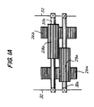
- Fig. 1 is a schematic block diagram of an illustrative embodiment of the actuator assembly of this invention.
- Fig. 1a is a view taken along the line 1A-1A in Fig. 1.
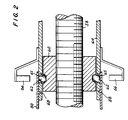
- Fig. 2 is a simplified longitudinal sectional view of a portion of the apparatus of Fig. 1.
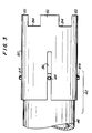
- Fig. 3 is a simplified elevational view of a portion of the apparatus of Fig. 1.
- FIG. 4 is a simplified longitudinal sectional view of an alternative embodiment of a portion of the apparatus of FIG. 1.
- FIG. 5A is a view similar to a portion of FIG. 4 showing one possible modification of that apparatus.
- FIG. 5B is a view similar to FIG. 5A showing that apparatus after release.
- FIGS. 6A and 7A show alternative ways of constructing a portion of the apparatus of FIG. 5, and FIGS. 6B and 7B show the apparatus of FIGS. 6A and 7A, respectively, in the operating condition depicted in FIG. 5B.
- FIGS. 8A and 8B are respectively similar to FIGS. 5A and 5B, and show another possible modification of the apparatus of FIG. 4.
- FIGS. 9 and 10 are similar to FIGS. 5A and 8A, and show two more possible modifications of the apparatus of FIG. 4.
- FIG. 11 is a simplified longitudinal sectional view of another alternative embodiment of a portion of the apparatus of FIG. 1.
- a typical fail-free actuator assembly 10 constructed in accordance with the principles of this invention includes first and second motors 12a and 12b, each of which may be a conventional rotary electric motor.
- Motors 12 are preferably identical to one another (although they may rotate in opposite directions). When actuator assembly 10 is operating normally, both motors rotate at the same time at the same speed.
- the kinetic energy output of motor 12a is rotating armature shaft 14a; the kinetic energy output of motor 12b is rotating armature shaft 14b.
- monitor device 16 is a mechanical differential-type device which produces an output proportional to the difference in the rate at which shafts 14 rotate.
- Spur gear 20a rotates with shaft 14a
- spur gear 20b similarly rotates with shaft 14b.
- Spur gear 22a meshes with spur gear 20a and thereby transmits the rotation of spur gear 20a to spur gear 26a via shaft 24a.
- Elements 22b, 24b, and 26b perform similarly with respect to the rotation of spur gear 20b.
- Spur gear 26a meshes with spur gear 28a, which is rotatable mounted on a shaft 30a connected to housing or cage 32.
- Spur gear 26b meshes with spur gear 28b, which is rotatably mounted on a shaft 30b connected to cage 32.
- Spur gears 28 mesh with one another.
- Cage 32 is rotatable about the coaxial longitudinal axes of shafts 24. Accordingly, as long as shafts 14 are rotating in the opposite directions at the same speed, gears 28 also rotate in the opposite directions at the same speed and therefore hold cage 32 stationary (i.e., prevent cage 32 from rotating in either direction about the longitudinal axes of shafts 24). On the other hand, if shafts 14 begin to rotate at different speeds, gears 28 also rotate at different speeds, which causes cage 32 to rotate about the longitudinal axes of shafts 24.
- the rotational position of cage 32 is therefore proportional to the time integral of the instantaneous difference in the angular speeds of shafts 14. Stated another way, the rotational position of cage 32 indicates the cumulative difference in the amounts of angular motion of shafts 14, the relative angular positions of shafts 14, or the phase difference between shafts 14.
- the rotational position of cage 32 is conveyed to quick-release actuator 80 by member 40. Note that monitor differential 16 does not transmit the kinetic energy outputs of motors 12; it merely monitors those outputs (in particular, the relative rates, amounts, or phases of those outputs).
- torque limiter 50a On the side of monitor differential 16 remote from motor 12a, shaft 14a is connected to torque limiter 50a. Shaft 14b is similarly connected to torque limiter 50b.
- torque limiters 50 is a conventional device (e.g., a detent- or clutch-type device) for limiting the amount of torque that can be transmitted from the associated input shaft 14 to the associated output shaft 52.
- the torque limits of devices 50a and 50b are different from one another. (Either of torque limiters 50 can be eliminated if desired.)
- devices 50a and 50b transmit all of the torque from shafts 14 to shafts 52. If the torque required to turn the output shaft 52 of either torque limiter becomes too high, however, the associated motor 12 has sufficient power to cause that torque limiter to "break-out", thereby allowing the associated shaft 14 to turn faster than normal relative to that shaft 52.
- gears 54 and 56 normally cooperate to sum the kinetic energy outputs of motors 12 and to apply that kinetic energy sum to rotate threaded shaft 58.
- Shaft 58 threadedly engages collar 60 (see FIG. 2) so that rotation of shaft 58 causes translation of collar 60 parallel to the longitudinal axis of shaft 58.
- Collar 60 is normally linked to bracket 64 by a plurality of balls 62 spaced around the circumference of collar 60.
- the load to be moved by actuator assembly 10 is connected to the right-hand end of bracket 64 in FIG. 1.
- Each ball 62 is mutually disposed in a recess 61 in the outer surface of collar 60 and an aperture 65 in bracket 64.
- Each ball is normally retained in elements 61 and 65 by quick-release actuator 80, which is shown in more detail in FIG. 3.
- actuator 80 has a longitudinal projection 82 adjacent each ball 62. Between projections 82, however, actuator 80 has recesses 84.
- actuator 80 is rotated by a sufficient amount in either direction about the longitudinal axis of shaft 58, balls 62 will no longer be retained in elements 61 and 65 by projections 82, but will instead be free to pass through recesses 84 and adhere to magnets 66. This uncouples bracket 64 from collar 60.
- the angular position of quick-release actuator 80 is controlled by the angular position of cage 32. Actuator 80 is constrained to move axially with bracket 64 by lugs 88 extending radially inwardly into annular slot 68 in the outer surface of bracket 64.
- Telescopic coupling 42 (i.e., a coupling which allows quick-release actuator 80 to move longitudinally but not angularly relative to cage 32) is included between elements 32 and 80.
- telescopic coupling 42 may include lugs 44 extending radially outwardly from coupling member 46 (connected to cage 32) into axially extending slots 86 in actuator 80.
- FIG. 4 shows an alternative embodiment in which quick release actuator 180 releases when capture ring 182 translates parallel to the longitudinal axis of shaft 158.
- Elements 40, 52, and 54 in FIG. 4 are the same as the correspondingly numbered elements in FIG. 1.
- Spur gears 54 engage teeth on the outer surface of hollow cylindrical member 184 in order to rotate member 184 about the longitudinal axis of shaft 158 when gears 54 are rotated.
- pins 186 (which extend through member 184 into recesses 188 in the outer surface of collar 190) cause collar 190 to rotate with member 184.
- Collar 190 threadedly engages shaft 158 so that shaft 158 translates parallel to its longitudinal axis in response to rotation of collar 190.
- Bracket 64 (similar to bracket 64 in FIG. 1) is connected to the end of shaft 158 and therefore translates with shaft 158.
- Pins 186 are normally held in recesses 188 by capture ring 182.
- Shaft 40 conveys any rotation of cage 32 (FIG. 1) to spur gear 192 which engages axially extending teeth in the outer surface of capture ring 182.
- a fixed finger 194 extends into a spiral recess 196 also formed in the outer surface of capture ring 182.
- shaft 40 does not rotate, so that capture ring 182 also does not rotate. If the actuator malfunctions, however, cage 32 rotates as described above in connections with FIG. 1. This causes elements 40, 192, and 182 to also rotate. As capture ring 182 rotates, elements 194 and 196 cooperate to cause the capture ring to translate parallel to the longitudinal axis of shaft 158.
- pin 186 has an annular recess 186a
- the capture device is a spring 166a which springs into recess 186a as shown in FIG. 5B when pin 186 moves radially outward.
- Spring 166a may either have two opposing tines and be secured to cylindrical member 184 by screw 166b as shown in FIG. 6, or may have a single tine and be both secured and prestressed by pins 166c and 166d.
- a shutter or sleeve 166e actuated by spring 166f prevents pin 186 from returning to its radially inward position after it has moved outward.
- function is performed by spring-loaded ball 166g entering annular slot 186b in pin 186.
- FIG. 11 shows how the embodiment of FIG. 4 can be modified to produce a fail-free rotary actuator.
- Elements in FIG. 11 which are substantially the same as elements in FIG. 4 have either the same reference numbers in FIG. 11 or reference numbers which are increased by 100 over the corresponding reference numbers in FIG. 4.
- spur gears 54 engage teeth in the outer surface of hollow cylindrical member 284. Pins 286 extend through member 284 into recesses 288 in output shaft 258. Accordingly, rotation of spur gears 54 normally causes rotation of member 284 and output shaft 258.
Landscapes
- Engineering & Computer Science (AREA)
- General Engineering & Computer Science (AREA)
- Mechanical Engineering (AREA)
- Automation & Control Theory (AREA)
- Aviation & Aerospace Engineering (AREA)
- Transmission Devices (AREA)
- Structure Of Transmissions (AREA)
Claims (29)
- Stellglied-Anordnung (10) zum selektiven Bewegen einer Last, welche Stellglied-Anordnung umfaßt:
erstes Mittel (12a), um normalerweise eine erste rotationskinetische Ausgangsenergie (14a) zu erzeugen;
zweites Mittel (12b), um normalerweise eine zweite rotations-kinetische Ausgangsenergie (14b) gleichzeitig mit der ersten rotations-kinetischen Ausgangsenergie (14a) zu erzeugen;
drittes Mittel (56), das in Reaktion auf die erste und die zweite rotations-kinetische Ausgangsenergie (14) normalerweise eine dritte rotations-kinetische Ausgangsenergie (58) erzeugt, welche die Summe der ersten und zweiten rotations-kinetischen Ausgangsenergien (14) ist;
viertes Mittel (60, 64), um normalerweise die dritte rotations-kinetische Ausgangsenergie (58) an die Last anzulegen, um die Last bewegen zu lassen;
erstes kraftbegrenzendes Kopplungsmittel (50a), das wirksam zwischen dem ersten Mittel (12a) und dem dritten Mittel (56) angeschlossen ist, um eine Übertragung einer Kraft, die eine erste vorbestimmte Kraftschwelle überschreitet, von dem ersten Mittel (12a) zu dem dritten Mittel (56) über die erste rotations-kinetische Ausgangsenergie (14a) zu vermeiden;
fünftes Mittel (16) zum Überwachen der ersten und der zweiten rotations-kinetischen Ausgangsenergie (14) und zum Erzeugen einer Abgabeanzeige, falls die Beziehung zwischen der ersten und zweiten rotations-kinetischen Ausgangsenergie (14) von einer vorbestimmten Beziehung abweicht, und
sechstes Mittel (40, 4280), in Abhängigkeit von der Abgabeanzeige, um das vierte Mittel (60, 64) zwangsweise die Last von der dritten Ausgangsenergie (58) zu lösen und so die Last frei bewegen zu lassen. - Stellglied-Anordnung (10) nach Anspruch 1, bei dem die Last frei zur Bewegung relativ zur dritten rotations-kinetischen Ausgangsenergie (58) ist, wenn das sechste Mittel (40, 42, 80) das vierte Mittel (60, 64) die Last von der dritten rotations-kinetischen Ausgangsenergie abtrennen läßt.
- Stellglied-Anordnung (10) nach Anspruch 1, bei der das fünfte Mittel (16) umfaßt:
siebtes Mittel (22, 24, 26, 28, 30, 32) zum Bestimmen des Zeitintegrals der augenblicklichen Differenz zwischen den Bewegungen der ersten und zweiten rotations-kinetischen Ausgangsenergien (14) und zur Erzeugung einer Ausgangsanzeige in dem Fall, daß das Zeitintegral einen vorbestimmten Zeitintegral-Schwellwert überschreitet. - Stellglied-Anordnung (10) nach Anspruch 1, bei der die Ausgangsanzeige die Bewegung eines mechanischen Elements (32) ist, wobei das vierte Mittel (60, 64) Riegelmittel (62, 82, 84) zum losbaren Verbinden des dritten kinetischen Ausgangsenergie (58) mit der Last umfaßt, und wobei das sechste Mittel (40, 42, 80) Riegel-Lösemittel (80) zum Lösen des Riegelmittels (62, 82, 84) in Reaktion auf Bewegung des mechanischen Elements (32) umfaßt.
- Stellglied-Anordnung (10) nach Anspruch 4, bei der das Riegelmittel (62, 82, 84) ein mechanischer Riegel ist, das Riegel-Lösemittel (80) eine mechanische Riegellösung ist und die Stellglied-Anordnung (10) weiter umfaßt eine mechanische Verbindung (40, 42) zwischen dem mechanischen Element (32) und der mechanischen Riegellösung (80).
- Stellglied-Anordnung (10) nach Anspruch 3, bei der das siebte Mittel (16) umfaßt:
eine mechanische Differentialanordnung (20, 22, 24, 26, 28, 30, 32) zur Erzeugung von Bewegung eines Ausgangsgliedes (32) proportional zu der Differenz zwischen der Bewegungsgröße von ersten und zweiten Eingangsgliedern (14a, 14b);
Mittel zum Koppeln des ersten Eingangsglieds (14) mit der ersten rotations-kinetischen Ausgangsenergie (52a); und Mittel zum Koppeln des zweiten Eingangsgliedes (14b) mit dem zweiten rotations-kinetischen Ausgangsenergie (52b, c, d), wobei die Bewegung des Ausgangsgliedes die Ausgangsanzeige ist. - Stellglied-Anordnung (10) nach Anspruch 1, die weiter umfaßt:
zweites Kraftbegrenzungs-Kopplungsmittel (50b), das wirksam zwischen dem zweiten Mittel (12b) und dem dritten Mittel (56) angeschlossen ist, um das Übertragen einer Kraft, die eine zweite vorbestimmte Kraftschwelle überschreitet, von dem zweiten Mittel (12b) zu dem dritten Mittel (56) über die zweite rotations-kinetische Ausgangsenergie zu verhindern. - Stellglied-Anordnung (10) nach Anspruch 7, bei der die erste und die zweite vorbestimmte Kraftschwelle im wesentlichen voneinander verschieden sind.
- Stellglied-Anordnung (10) nach Anspruch 8, bei der das fünfte Mittel umfaßt:
eine mechanische Differentialanordnung (20, 22, 24, 26, 28, 30, 32) zur Erzeugung von Bewegung eines Ausgangsgliedes 832, 40) proportional zur Differenz zwischen der Bewegungsgröße von ersten und zweiten Eingangsgliedern (14a, 14b), wobei die Bewegung des Ausgangsgliedes (32, 40) die Ausgangsanzeige ist;
Mittel zum Verbinden des ersten Eingangsgliedes (14a) mit der ersten rotations-kinetischen Ausgangsenergie (52a), so daß die Bewegung des ersten Eingangsgliedes (14a) proportional zur Bewegung der ersten rotations-kinetischen Ausgangsenergie (52a) ist; und
Mittel zum Verbinden des zweiten Eingangsgliedes (14b) mit der zweiten rotations-kinetischen Ausgangsenergie (52b, c, d), so daß die Bewegung des zweiten Eingangsgliedes (14b) proportional zu der Bewegung der zweiten rotations-kinetischen Ausgangsenergie (52b, c, d) ist. - Stellglied-Anordnung (10) nach Anspruch 9, bei der das vierte Mittel (60, 64) eine lösbare mechanische Verbindung (61, 62, 65) zwischen der dritten rotations-kinetischen Ausgangsenergie (58) und der Last umfaßt, und wobei das sechste Mittel (40, 42, 50) auf die Bewegung des Ausgangsgliedes (32, 40) zum Lösen der mechanischen Verbindung (61, 62, 65) reagierendes mechanisches Mittel (82, 84) umfaßt.
- Stellglied-Anordnung (10) nach Anspruch 1, bei der das erste bzw. zweite Mittel (12) jeweils einen ersten (12a) bzw. zweiten (12b) Motor umfaßt.
- Stellglied-Anordnung (10) nach Anspruch 11, bei der der erste Motor (12a) die erste rotations-kinetische Ausgangsenergie durch Drehen einer ersten Welle (14a) erzeugt und bei der der zweite Motor (12b) die zweite rotations-kinetische Ausgangsenergie durch Drehen einer zweiten Welle (14b) erzeugt.
- Stellglied-Anordnung (10) nach Anspruch 12, bei der das erste Kraftbegrenzungs-Kopplungsmittel (50a) umfaßt:
einen zwischen der ersten Welle (14a) und dem dritten Mittel angeschlossenen Drehmomentbegrenzer (50a) zum begrenzen der Drehmomentgröße, die an das dritte Mittel (56) von der ersten Welle (14a) angelegt werden kann. - Stellglied-Anordnung (10) nach Anspruch 12, bei der das dritte Mittel (56) die dritte rotations-kinetische Ausgangsenergie (58) durch Drehen einer dritten Welle (58) erzeugt.
- Stellglied-Anordnung (10) nach Anspruch 14, bei der das vierte Mittel (60, 64) umfaßt:
ein Gewinde an der dritte Welle (58);
ein Folgeglied (60) zum Eingriff mit dem Gewinde, so daß, wenn die dritte Welle (58) um ihre Längsachse gedreht wird, das Folgeglied (60) sich parallel zu der Längsachse verschiebt; und
Kopplungsmittel (61, 62, 65) zum lösbaren Koppeln der Last mit dem Folgeglied (60). - Stellglied-Anordnung (10) nach Anspruch 15, bei der das sechste Mittel (40, 42, 80) das Kopplungsmittel (61, 62, 65) zum Entkoppeln der Last von dem Folgeglied (60) veranlaßt.
- Stellglied-Anordnung (10) nach Anspruch 16, bei der das fünfte Mittel (16) umfaßt:
ein erstes mit der ersten Welle (14a) drehbares Zahnrad (20a);
ein zweites mit der zweiten Welle (14b) drehbares Zahnrad (20b); und
eine Differentialgetriebe-Anordnung (22, 24, 26, 28, 30, 32) einschließlich Differentialgetriebemittel (22, 24, 26, 28, 30), das drehbar in einem Gehäuseteil (32) angebracht ist, wobei das Differentialgetriebemittel (22, 24, 26, 28, 30) mit sowohl dem ersten wie auch dem zweiten Zahnrad (20) in Eingriff ist, so daß, wenn das erste und das zweite Zahnrad (20) sich mit der gleichen Rate drehen, das Differentialgetriebemittel (22, 24, 26, 28, 30) das Gehäuseteil (32) stationär hält, jedoch, wenn das erste und das zweite Zahnrad (20) sich nicht mit der gleichen Rate drehen, das Differentialgetriebe (22, 24, 26, 28, 30) das Gehäuseteil (32) zur Bewegung veranlaßt. - Stellglied-Anordnung (10) nach Anspruch 17, bei der das sechste Mittel (40, 42, 80) Mittel zum Verbinden des Gehäuseteils (32) mit dem Kopplungsmittel (61, 62, 65) umfaßt, so daß eine Bewegung des Gehäuseteils (32) das Kopplungsmittel (61, 62, 65) veranlaßt, die Last von dem Folgeglied (60) zu entkoppeln.
- Stellglied-Anordnung (10) nach Anspruch 18, bei der das Kopplungsmittel (61, 62, 65) umfaßt:
eine Vertiefung (61) in einer Fläche des Folgegliedes (60), die im wesentlichen parallel zur Längsachse der dritten Welle (58) ist;
einen Bund (64) benachbart der Fläche mit einem Durchbruch (65) benachbart der Vertiefung (61);
ein Rückhalteteil (80), das relativ zu dem Bund (64) bewegbar an der dem Durchbruch (65) abgewendeten Seite des Bundes (64) angebracht ist;
Mittel (40, 42) zum Verbinden des Gehäuseteils (32) mit dem Rückhalteteil (82) so, daß das Rückhalteteil (80) anfangs dem Durchbruch (65) benachbart ist, jedoch so, daß, wenn das Gehäuseteil (32) sich bewegt, das Rückhalteteil (80) sich von dem Durchbruch (65) weg bewegt; und
eine Kugel (62), die wechselweise in der Vertiefung (61) und dem Durchbruch (65) untergebracht und darin durch das Halteteil (80) zurückgehalten ist, wenn nicht das Halteteil (80) von dem Durchbruch (65) durch Bewegung des Gehäuseteils (32) wegbewegt wird. - Stellglied-Anordnung (10) nach Anspruch 14, bei der das vierte Mittel (60, 64) umfaßt:
ein mit der dritten Welle (58) konzentrisches Folgeglied (60);
Kopplungsmittel (61, 62, 65) zum lösbaren Koppeln des Folgegliedes (60) mit der dritten Welle (50), so daß, wenn die dritte Welle (58) um ihre Längsachse gedreht wird, das Folgeglied (60) sich um die dritte Welle (58) dreht; und
eine vierte Welle in konzentrischem Gewindeeingriff mit dem Folgeglied (60), so daß, wenn das Folgeglied (60) sich mit der dritten Welle (58) dreht, das Folgeglied (60) sich parallel zur Längsachse der dritten Welle (58) verschiebt. - Stellglied-Anordnung (10) nach Anspruch 20, bei der das sechste Mittel (40, 42, 80) das Kopplungsmittel (61, 62, 65) zum Entkoppeln des Folgegliedes (60) von der dritten Welle (58) veranlaßt.
- Stellglied-Anordnung (10) nach Anspruch 21, bei dem das fünfte Mittel (16) umfßat:
ein erstes mit der ersten Welle (14a) drehbares Zahnrad (20a);
ein zweites mit der zweiten Welle (14b) drehbares Zahnrad (20b); und
eine Differentialgetriebe-Anordnung (22, 24, 26, 28, 30, 32) einschließlich Differentialzahnradmittel (22, 24, 26, 28, 30), die drehbar in einem Gehäuseteil (32) angebracht sind, wobei das Differentialzahnradmittel (22, 24, 26, 28, 30) mit sowohl dem ersten als auch dem zweiten Zahnrad (20) in Eingriff ist, so daß, wenn das erste und das zweite Zahnrad (20) sich mit der gleichen Rate drehen, das Differentialzahnradmittel (22, 24, 26, 28, 30) das Gehäuseteil (32) stationär hält, jedoch, wenn das erste und das zweite Zahnrad (20) sich nicht mit der gleichen Rate drehen, das Differentialzahnradmittel (22, 24, 26, 28, 30) das Gehäuse (32) zur Bewegung veranlaßt. - Stellglied-Anordnung (10) nach Anspruch 22, bei der das sechste Mittel (40, 42, 80) Mittel (40, 42) umfaßt zum Verbinden des Gehäuseteils (32) mit dem Kopplungsmittel (61, 62, 65), so daß eine Bewegung des Gehäuseteils (32) das Kopplungsmittel (61, 62, 65) veranlaßt, das Folgeglied (60) von der dritten Welle (58) zu entkoppeln.
- Stellglied-Anordnung (10) nach Anspruch 23, bei der das Kopplungsmittel umfaßt:
eine Vertiefung (188) in einer Oberfläche des Folgegliedes (190), die im wesentlichen parallel zur Längsachse der dritten Welle (158) ist;
einen Stift (186), der sich durch die dritte Welle so erstreckt, daß das erste Ende des Stiftes (186) normalerweise in die Vertiefung (188) vorsteht;
einen Einfangring (182) benachbart dem zweiten Ende des Stiftes, das von der Vertiefung (188) abgelegen ist, um normalerweise das erste Ende des Stiftes (186) in der Vertiefung (188) zu halten; und
Mittel (40, 192) zum Verbinden des Gehäusegliedes (32) mit dem Einfangring (182) in der Weise, daß der Einfangring (182) anfangs der Vertiefung (188) benachbart ist, jedoch so, daß wenn das Gehäuseglied (32) sich bewegt, der Einfangring (182) sich von dem zweiten Ende des Stiftes (186) weg bewegt und dadurch zuläßt, daß das erste Ende des Stiftes (186) aus der Vertiefung (188) entweicht. - Stellglied-Anordnung (10) nach Anspruch 14, bei der das vierte Mittel umfaßt:
eine vierte Welle (158), die mit der dritten Welle (184) konzentrisch ist; und
Kopplungsmittel (182, 186, 188) zum lösbaren Koppeln der vierten Welle (158) mit der dritten Welle (184), so daß, wenn die dritte Welle (184) um ihre Längsachse gedreht wird, die vierte Welle (158) sich mit der dritten Welle (184) dreht. - Stellglied-Anordnung (10) nach Anspruch 25, bei der das sechste Mittel (40, 42) das Kopplungsmittel (182, 186, 188) zum Entkoppeln der vierten Welle (158) von der dritten Welle (184) veranlaßt.
- Stellglied-Anordnung (10) nach Anspruch 26, bei der das fünfte Mittel (16) umfaßt:
ein erstes Zahnrad (20a), das mit der ersten Welle (14a) drehbar ist;
ein zweites Zahnrad (20b), das mit der zweiten Welle (14b) drehbar ist; und
eine Differentialgetriebe-Anordnung (22, 24, 26, 28, 30, 32) einschließlich Differentialzahnradmittel (22, 24, 26, 28, 30), das drehbar in einem Gehäuseteil (32) angeordnet sind, wobei das Differentialzahnradmittel (22, 24, 26, 28, 30) mit sowohl dem ersten wie dem zweiten Zahnrad (20) in Eingriff ist, so daß, wenn das erste und das zweite Zahnrad (20) sich mit der gleichen Rate drehen, das Differentialzahnradmittel (22, 24, 26, 28, 30) das Gehäuseteil (22) stationär hält, aber, wenn das erste und das zweite Zahnrad (20) sich nicht mit der gleichen Rate drehen, das Differentialzahnradmittel (22, 24, 26, 28, 30) das Gehäuseteil (32) zur Bewegung veranlaßt. - Stellglied-Anordnung (10) nach Anspruch 27, bei dem das sechste Mittel Mittel (40, 192) zum Verbinden des Gehäuseteils (32) mit dem Kopplungsmittel (182, 186, 188) umfaßt, so daß eine Bewegung des Gehäuseteils 82) das Kopplungsmittel (182, 186, 188) zum Entkoppeln der vierten Welle 8158) von der dritten Welle (184) veranlaßt.
- Stellglied-Anordnung (10) nach Anspruch 28, bei der das Kopplungsmittel (182, 186, 188) umfaßt:
eine Vertiefung (188) in der Oberfläche der vierten Welle (158), die im wesentlichen parallel zur Längsachse der dritten Welle (184) ist;
einen Stift (186), der sich durch die dritte Welle (184) so erstreckt, daß ein erstes Ende des Stiftes normalerweise in die Vertiefung (188) vorsteht;
einen Einfangring (182) benachbart dem zweiten, von der Vertiefung (188) abgewendeten Ende des Stiftes (186), um normalerweise das erste Ende des Stiftes (186) in der Vertiefung (188) zu halten; und
Mittel (40, 192) zum Verbinden des Gehäuseteils (32) mit dem Einfangring (182) so, daß der Einfangring (182) anfangs dem Durchbruch (188) benachbart ist, jedoch so, daß, wenn das Gehäuseteil (32) sich bewegt, der Einfangring (182) sich von dem zweiten Ende des Stiftes (186) weg bewegt und dadurch zuläßt, daß das erste Ende des Stiftes (186) sich aus der Vertiefung (188) entfernt.
Applications Claiming Priority (4)
| Application Number | Priority Date | Filing Date | Title |
|---|---|---|---|
| US14630188A | 1988-01-21 | 1988-01-21 | |
| US146301 | 1988-01-21 | ||
| US07/183,928 US4858491A (en) | 1988-01-21 | 1988-04-20 | Fail-free actuator assembly |
| US183928 | 1988-04-20 |
Publications (2)
| Publication Number | Publication Date |
|---|---|
| EP0325027A1 EP0325027A1 (de) | 1989-07-26 |
| EP0325027B1 true EP0325027B1 (de) | 1993-08-18 |
Family
ID=26843772
Family Applications (1)
| Application Number | Title | Priority Date | Filing Date |
|---|---|---|---|
| EP88310243A Expired - Lifetime EP0325027B1 (de) | 1988-01-21 | 1988-11-01 | Betätigungseinrichtung mit Lösemechanismus für den Störfall |
Country Status (4)
| Country | Link |
|---|---|
| US (1) | US4858491A (de) |
| EP (1) | EP0325027B1 (de) |
| JP (1) | JPH01238758A (de) |
| DE (1) | DE3883365D1 (de) |
Families Citing this family (49)
| Publication number | Priority date | Publication date | Assignee | Title |
|---|---|---|---|---|
| US5511439A (en) * | 1994-07-22 | 1996-04-30 | Las Navas Garcia; Jose M. | Pushing mechansim |
| US5628234A (en) * | 1995-10-30 | 1997-05-13 | Gec-Marconi Aerospace Inc. | Fail-free actuator assembly |
| US5918836A (en) * | 1997-03-25 | 1999-07-06 | Sundstrand Corporation | Aircraft spoiler blow-down mechanism |
| US5957798A (en) | 1997-09-10 | 1999-09-28 | Gec-Marconi Aerospace Inc. | Fail-free actuator assembly |
| DE59708507D1 (de) * | 1997-11-03 | 2002-11-21 | Honeywell Ag | Einrichtung zur Erzeugung einer Längsbewegung und -oder einer Drehbewegung |
| FR2778797B1 (fr) * | 1998-05-12 | 2000-08-04 | Lucas Aerospace Fcs | Actionneur electro-mecanique du type a systeme vis/ecrou |
| US6461265B1 (en) * | 2000-02-02 | 2002-10-08 | Ex-Cello Machine Tools, Inc. | Coaxial gear box |
| WO2001071217A1 (en) * | 2000-03-22 | 2001-09-27 | Alliedsignal Inc. | Dual load path ball screw with thrust bearing |
| FR2832685A1 (fr) * | 2001-11-23 | 2003-05-30 | Conception & Dev Michelin Sa | Direction electrique pour vehicule, a redondance triple |
| DE10308301B3 (de) * | 2003-02-26 | 2004-07-15 | Liebherr-Aerospace Lindenberg Gmbh | Flugzeughochauftriebssystem mit Überlastsicherung |
| US20050084345A1 (en) * | 2003-10-17 | 2005-04-21 | Frye Randy C. | Dual motor tapping machine |
| US7098619B2 (en) * | 2004-01-28 | 2006-08-29 | Stridsberg Innovation Ab | Actuator and movement linkage system |
| US7834494B2 (en) * | 2004-06-04 | 2010-11-16 | The Boeing Company | Fault-tolerant electromechanical actuator having a torque sensing control system |
| US7190096B2 (en) * | 2004-06-04 | 2007-03-13 | The Boeing Company | Fault-tolerant electro-mechanical actuator having motor armatures to drive a ram and having an armature release mechanism |
| US7211971B2 (en) * | 2005-03-31 | 2007-05-01 | Hitachi Automotive Products (Usa), Inc. | Linear actuator |
| US7560888B2 (en) * | 2005-09-08 | 2009-07-14 | Honeywell International Inc. | Electromechanical actuator including redundant, dissimilar position feedback |
| US7536927B2 (en) * | 2006-06-05 | 2009-05-26 | Brose Fahrzeugteile GmbH & Co. Kommanditgesellschaft, Würzburg | Window lift drive for raising and lowering windows in a vehicle door |
| ES2353975T3 (es) | 2006-10-18 | 2011-03-08 | Moog Inc. | Accionadores de tipo diferencial con redundancia, resistentes al bloqueo. |
| GB0719689D0 (en) * | 2007-10-09 | 2007-11-14 | Goodrich Actuation Systems Ltd | Actuator arrangement |
| DE102008047521A1 (de) * | 2008-09-16 | 2010-04-15 | Mbb Palfinger Gmbh | Hubladebühne |
| US8499653B1 (en) * | 2009-06-18 | 2013-08-06 | The Boeing Company | Fault tolerant electro-mechanical actuator |
| US8925586B2 (en) | 2009-07-14 | 2015-01-06 | Woodward Hrt, Inc. | Direct drive servovalve having redundant drive motors |
| US8322242B2 (en) * | 2009-09-29 | 2012-12-04 | Hamilton Sundstrand Corporation | Velocity summing linear actuator |
| US8127912B2 (en) * | 2009-12-15 | 2012-03-06 | Hamilton Sundstrand Corporation | Feedback torque limiter |
| US8424416B2 (en) * | 2010-06-18 | 2013-04-23 | Hamilton Sundstrand Corporation | Layshaft generator |
| EP2415669B1 (de) | 2010-08-04 | 2015-05-13 | AIRBUS HELICOPTERS DEUTSCHLAND GmbH | Steuersystem |
| GB2489503A (en) * | 2011-03-31 | 2012-10-03 | Ge Aviat Systems Ltd | Rotary actuator and method of operation with failsafe mechanism |
| GB2490959A (en) | 2011-05-20 | 2012-11-21 | Ge Aviat Systems Ltd | High integrity linear actuator |
| BR112014019610A8 (pt) | 2012-02-09 | 2017-07-11 | Moog Inc | Sistema de atuador, atuador, e, método de controlar um sistema de atuador |
| US9255632B2 (en) | 2012-05-23 | 2016-02-09 | Hamilton Sundstrand Corporation | Integrated torque limiter/no-back device |
| US9086125B2 (en) | 2013-03-15 | 2015-07-21 | Moog Inc. | Rotary actuator |
| EP2981740A1 (de) * | 2013-04-03 | 2016-02-10 | Thomson Industries Inc. | Verdrehsichere vorrichtung für ein linearstellglied und linearstellglied damit |
| CN103968811B (zh) * | 2013-04-18 | 2016-02-17 | 常州华达科捷光电仪器有限公司 | 一种调整机构及具有该调整机构的激光准直仪器 |
| EP3052835A2 (de) * | 2013-10-02 | 2016-08-10 | Linak A/S | Linearer aktuator |
| CN104595451B (zh) * | 2013-10-31 | 2017-04-05 | 北京精密机电控制设备研究所 | 一种双输入通道差速器式机电作动器 |
| EP3143306B1 (de) | 2014-05-16 | 2021-06-23 | Bombardier Inc. | Aktuatoren und verfahren für flugzeugflugsteuerungsoberflächen |
| US9586675B2 (en) * | 2014-06-09 | 2017-03-07 | The Boeing Company | Apparatus and method for arrestment of a flight control surface |
| TWI550216B (zh) * | 2014-07-21 | 2016-09-21 | 第一傳動科技股份有限公司 | 線性致動器 |
| US10066715B2 (en) | 2015-04-24 | 2018-09-04 | Moog Inc. | Fail-safe electromechanical actuator |
| US10024405B2 (en) * | 2015-05-12 | 2018-07-17 | Hamilton Sundstrand Corporation | Dual redundant linear actuator |
| JP6835855B2 (ja) | 2016-01-13 | 2021-02-24 | ムーグ インコーポレーテッド | 合成および耐故障性の回転式アクチュエータアセンブリ |
| FR3055308B1 (fr) * | 2016-08-26 | 2018-08-17 | Safran Aircraft Engines | Moyen de commande d'un systeme de changement de pas comprenant un dispositif anti-rotation, systeme de changement de pas equipe dudit moyen de commande et turbomachine correspondante |
| IT201700058891A1 (it) * | 2017-05-30 | 2018-11-30 | Umbragroup S P A | Metodo per verificare un guasto elettrico, elettronico e/o meccanico in un attuatore elettromeccanico lineare |
| CN111137437A (zh) * | 2019-12-27 | 2020-05-12 | 航天时代飞鸿技术有限公司 | 一种双余度电动舵机 |
| US12234900B2 (en) * | 2020-02-06 | 2025-02-25 | Exonetik Inc. | Low-impedance actuation device using magnetorheological fluid clutch apparatuses |
| TWM614035U (zh) * | 2021-03-09 | 2021-07-01 | 第一傳動科技股份有限公司 | 具有可限位快速釋放結構的線性致動器 |
| US11591192B2 (en) * | 2021-03-29 | 2023-02-28 | Elgoteam Ltd | Electro mechanical operated bollard |
| CN113697089B (zh) * | 2021-08-26 | 2024-06-11 | 航天时代飞鹏有限公司 | 一种电气双余度舵机 |
| IT202200020793A1 (it) * | 2022-10-10 | 2024-04-10 | Umbragroup S P A | Attuatore elettromeccanico lineare perfezionato |
Family Cites Families (26)
| Publication number | Priority date | Publication date | Assignee | Title |
|---|---|---|---|---|
| US2630022A (en) * | 1951-10-26 | 1953-03-03 | Boeing Co | Dual screw drive |
| US3081664A (en) * | 1960-01-20 | 1963-03-19 | Voigtlaender Ag | Block type photographic viewfinder with parallax compensation |
| US3277736A (en) * | 1964-07-27 | 1966-10-11 | Goodman Robert | Device for translating rotary motion into linear motion |
| US3682283A (en) * | 1970-03-02 | 1972-08-08 | Mitumasa Sato | Motor-driven actuator and safety overload mechanism therefor |
| US3766790A (en) * | 1971-12-29 | 1973-10-23 | Boeing Co | Non-jamming ball screw linear actuator |
| US3735228A (en) * | 1972-01-03 | 1973-05-22 | E Systems Inc | Non-electronic servo actuator |
| US3858452A (en) * | 1973-07-09 | 1975-01-07 | Vemco Products Inc | Emergency release for screw drive operator traveler assembly |
| US3950686A (en) * | 1974-12-11 | 1976-04-13 | Trw Inc. | Series redundant drive system |
| US4046241A (en) * | 1976-03-24 | 1977-09-06 | Essex Group, Inc. | Over-ride mechanism for screw drive actuator |
| US4179944A (en) * | 1977-06-27 | 1979-12-25 | United Technologies Corporation | Fail safe redundant actuator |
| US4094481A (en) * | 1977-06-30 | 1978-06-13 | Sperry Rand Corporation | Fail passive dual servo with continuous motor speed and acceleration and monitoring |
| US4162438A (en) * | 1978-03-27 | 1979-07-24 | Sperry Rand Corporation | Dual servo automatic pilot with improved failure monitoring |
| US4226129A (en) * | 1978-04-12 | 1980-10-07 | Harvey Henderson | Worm drive mechanism |
| US4289996A (en) * | 1978-08-29 | 1981-09-15 | Frazer Nash Limited | Actuators |
| US4304375A (en) * | 1979-05-17 | 1981-12-08 | Textron Inc. | Electrically controlled elevator |
| FR2468798A1 (fr) * | 1979-09-11 | 1981-05-08 | Tech Integrale | Mecanisme debrayable, de vis et ecrou a roulement |
| DE3270901D1 (en) * | 1981-12-18 | 1986-06-05 | Lars Int Sa | Linear drive device with two motors |
| US4591313A (en) * | 1983-12-30 | 1986-05-27 | The Boeing Company | Propeller pitch control system and apparatus |
| US4574654A (en) * | 1984-01-30 | 1986-03-11 | Griffiths Edward E | Selectively engageable linear power actuator |
| CA1238210A (en) * | 1984-02-07 | 1988-06-21 | Yvan Poulin | Drive mechanism |
| FR2562028B1 (fr) * | 1984-04-03 | 1986-06-27 | Aerospatiale | Systeme pour la commande d'une surface aerodynamique horizontale a incidence variable d'un aeronef et agencement de commande hydraulique a servovalve pour un tel systeme |
| US4603594A (en) * | 1984-05-31 | 1986-08-05 | Sundstrand Corporation | Fail safe actuator |
| US4637272A (en) * | 1985-10-28 | 1987-01-20 | Sundstrand Corporation | Ballscrew actuator |
| US4663985A (en) * | 1986-03-07 | 1987-05-12 | Sundstrand Corporation | Shaft relative speed limiting system |
| US4751988A (en) * | 1986-03-17 | 1988-06-21 | Sundstrand Corporation | Torque limiting and overtravel stop device |
| US4745815A (en) * | 1986-12-08 | 1988-05-24 | Sundstrand Corporation | Non-jamming screw actuator system |
-
1988
- 1988-04-20 US US07/183,928 patent/US4858491A/en not_active Expired - Lifetime
- 1988-11-01 EP EP88310243A patent/EP0325027B1/de not_active Expired - Lifetime
- 1988-11-01 DE DE8888310243T patent/DE3883365D1/de not_active Expired - Lifetime
-
1989
- 1989-01-20 JP JP1010120A patent/JPH01238758A/ja active Pending
Also Published As
| Publication number | Publication date |
|---|---|
| JPH01238758A (ja) | 1989-09-22 |
| EP0325027A1 (de) | 1989-07-26 |
| DE3883365D1 (de) | 1993-09-23 |
| US4858491A (en) | 1989-08-22 |
Similar Documents
| Publication | Publication Date | Title |
|---|---|---|
| EP0325027B1 (de) | Betätigungseinrichtung mit Lösemechanismus für den Störfall | |
| RU2440915C2 (ru) | Привод, узел шасси летательного аппарата, летательный аппарат, набор частей привода и способ перемещения детали | |
| US6202803B1 (en) | Output load limiter | |
| KR102680123B1 (ko) | 합산 및 결함 허용성 로터리 액추에이터 어셈블리 | |
| US12404009B2 (en) | Drive arrangements | |
| US4643290A (en) | Bi-directional overtravel stop | |
| US12397903B2 (en) | Strain wave gearing and drive arrangements | |
| EP0404772B1 (de) | Nichtblockierender, rotierender, mechanischer steller | |
| US20250010979A1 (en) | Drive arrangements | |
| US5028828A (en) | Dual drive mechanism with a redundant feature | |
| GB2159599A (en) | Actuators | |
| GB2306610A (en) | Fail-free Actuator Assembly | |
| US4544052A (en) | Resettable disconnect device for rotating machines | |
| US12428137B2 (en) | Drive arrangements | |
| EP4190692A1 (de) | Antriebsanordnungen | |
| EP4190691A1 (de) | Antriebsanordnungen | |
| US4953675A (en) | Simply supported secondary shafting system torque sensor | |
| EP4191088A1 (de) | Dehnungswellengetriebe und antriebsanordnungen | |
| EP4296542A1 (de) | Verformungswellgetriebe | |
| EP4190686A1 (de) | Antriebsanordnungen | |
| GB2613380A (en) | Strain wave gearing and drive arrangements | |
| EP4190693A1 (de) | Antriebsanordnungen | |
| TR2024020350A2 (tr) | Manyeti̇k ve mekani̇k hi̇bri̇t yataklamali hiz/tork sinirlandirmali eyleyi̇ci̇ |
Legal Events
| Date | Code | Title | Description |
|---|---|---|---|
| PUAI | Public reference made under article 153(3) epc to a published international application that has entered the european phase |
Free format text: ORIGINAL CODE: 0009012 |
|
| AK | Designated contracting states |
Kind code of ref document: A1 Designated state(s): DE FR GB IT SE |
|
| 17P | Request for examination filed |
Effective date: 19900125 |
|
| 17Q | First examination report despatched |
Effective date: 19911022 |
|
| GRAA | (expected) grant |
Free format text: ORIGINAL CODE: 0009210 |
|
| AK | Designated contracting states |
Kind code of ref document: B1 Designated state(s): DE FR GB IT SE |
|
| PG25 | Lapsed in a contracting state [announced via postgrant information from national office to epo] |
Ref country code: IT Free format text: LAPSE BECAUSE OF FAILURE TO SUBMIT A TRANSLATION OF THE DESCRIPTION OR TO PAY THE FEE WITHIN THE PRE;WARNING: LAPSES OF ITALIAN PATENTS WITH EFFECTIVE DATE BEFORE 2007 MAY HAVE OCCURRED AT ANY TIME BEFORE 2007. THE CORRECT EFFECTIVE DATE MAY BE DIFFERENT FROM THE ONE RECORDED.SCRIBED TIME-LIMIT Effective date: 19930818 Ref country code: FR Effective date: 19930818 Ref country code: DE Effective date: 19930818 Ref country code: SE Effective date: 19930818 |
|
| REF | Corresponds to: |
Ref document number: 3883365 Country of ref document: DE Date of ref document: 19930923 |
|
| REG | Reference to a national code |
Ref country code: GB Ref legal event code: 732E |
|
| EN | Fr: translation not filed | ||
| PLBE | No opposition filed within time limit |
Free format text: ORIGINAL CODE: 0009261 |
|
| STAA | Information on the status of an ep patent application or granted ep patent |
Free format text: STATUS: NO OPPOSITION FILED WITHIN TIME LIMIT |
|
| 26N | No opposition filed | ||
| REG | Reference to a national code |
Ref country code: GB Ref legal event code: IF02 |
|
| REG | Reference to a national code |
Ref country code: GB Ref legal event code: 732E |
|
| PGFP | Annual fee paid to national office [announced via postgrant information from national office to epo] |
Ref country code: GB Payment date: 20071114 Year of fee payment: 20 |
|
| REG | Reference to a national code |
Ref country code: GB Ref legal event code: PE20 Expiry date: 20081031 |
|
| PG25 | Lapsed in a contracting state [announced via postgrant information from national office to epo] |
Ref country code: GB Free format text: LAPSE BECAUSE OF EXPIRATION OF PROTECTION Effective date: 20081031 |