EP0324668B1 - System for transforming wastes - Google Patents
System for transforming wastes Download PDFInfo
- Publication number
- EP0324668B1 EP0324668B1 EP89400037A EP89400037A EP0324668B1 EP 0324668 B1 EP0324668 B1 EP 0324668B1 EP 89400037 A EP89400037 A EP 89400037A EP 89400037 A EP89400037 A EP 89400037A EP 0324668 B1 EP0324668 B1 EP 0324668B1
- Authority
- EP
- European Patent Office
- Prior art keywords
- residues
- reactor
- conversion
- gas
- tank
- Prior art date
- Legal status (The legal status is an assumption and is not a legal conclusion. Google has not performed a legal analysis and makes no representation as to the accuracy of the status listed.)
- Expired - Lifetime
Links
- 239000002699 waste material Substances 0.000 title abstract description 6
- 230000001131 transforming effect Effects 0.000 title 1
- 238000006243 chemical reaction Methods 0.000 claims abstract description 21
- 238000010438 heat treatment Methods 0.000 claims abstract description 12
- 238000001914 filtration Methods 0.000 claims abstract description 8
- 238000000034 method Methods 0.000 claims abstract description 6
- 230000008569 process Effects 0.000 claims abstract description 6
- 238000000227 grinding Methods 0.000 claims abstract description 5
- 239000007789 gas Substances 0.000 claims description 39
- XLYOFNOQVPJJNP-UHFFFAOYSA-N water Substances O XLYOFNOQVPJJNP-UHFFFAOYSA-N 0.000 claims description 26
- 238000011282 treatment Methods 0.000 claims description 25
- 239000000463 material Substances 0.000 claims description 11
- OKTJSMMVPCPJKN-UHFFFAOYSA-N Carbon Chemical compound [C] OKTJSMMVPCPJKN-UHFFFAOYSA-N 0.000 claims description 9
- 238000000605 extraction Methods 0.000 claims description 7
- 230000005294 ferromagnetic effect Effects 0.000 claims description 7
- 230000032258 transport Effects 0.000 claims description 7
- 239000004033 plastic Substances 0.000 claims description 6
- 229920003023 plastic Polymers 0.000 claims description 6
- 238000000197 pyrolysis Methods 0.000 claims description 6
- 238000007599 discharging Methods 0.000 claims description 5
- 239000011521 glass Substances 0.000 claims description 5
- 230000005291 magnetic effect Effects 0.000 claims description 5
- 239000002245 particle Substances 0.000 claims description 5
- 229910052799 carbon Inorganic materials 0.000 claims description 4
- 238000001816 cooling Methods 0.000 claims description 4
- 239000003610 charcoal Substances 0.000 claims description 3
- 229910052751 metal Inorganic materials 0.000 claims description 3
- 239000002184 metal Substances 0.000 claims description 3
- 150000002739 metals Chemical class 0.000 claims description 3
- 239000007787 solid Substances 0.000 claims description 3
- 230000005540 biological transmission Effects 0.000 claims description 2
- 238000002347 injection Methods 0.000 claims description 2
- 239000007924 injection Substances 0.000 claims description 2
- 238000000746 purification Methods 0.000 claims description 2
- 239000011819 refractory material Substances 0.000 claims description 2
- 239000000725 suspension Substances 0.000 claims description 2
- 238000012546 transfer Methods 0.000 claims description 2
- 235000013311 vegetables Nutrition 0.000 claims description 2
- 238000005303 weighing Methods 0.000 claims description 2
- 238000011049 filling Methods 0.000 claims 1
- 238000000926 separation method Methods 0.000 claims 1
- 239000007921 spray Substances 0.000 claims 1
- 238000009434 installation Methods 0.000 description 17
- 230000009466 transformation Effects 0.000 description 9
- 238000011084 recovery Methods 0.000 description 6
- 239000000126 substance Substances 0.000 description 6
- 238000011068 loading method Methods 0.000 description 5
- 238000002485 combustion reaction Methods 0.000 description 4
- 239000012071 phase Substances 0.000 description 4
- 208000031968 Cadaver Diseases 0.000 description 3
- ZAMOUSCENKQFHK-UHFFFAOYSA-N Chlorine atom Chemical compound [Cl] ZAMOUSCENKQFHK-UHFFFAOYSA-N 0.000 description 3
- 239000002956 ash Substances 0.000 description 3
- 230000008901 benefit Effects 0.000 description 3
- 230000015572 biosynthetic process Effects 0.000 description 3
- 239000000460 chlorine Substances 0.000 description 3
- 229910052801 chlorine Inorganic materials 0.000 description 3
- 238000011109 contamination Methods 0.000 description 3
- 238000013461 design Methods 0.000 description 3
- 239000000446 fuel Substances 0.000 description 3
- 239000007788 liquid Substances 0.000 description 3
- 239000000203 mixture Substances 0.000 description 3
- 230000002378 acidificating effect Effects 0.000 description 2
- 230000005587 bubbling Effects 0.000 description 2
- 239000005539 carbonized material Substances 0.000 description 2
- 239000002361 compost Substances 0.000 description 2
- 238000010276 construction Methods 0.000 description 2
- 239000000428 dust Substances 0.000 description 2
- 239000012530 fluid Substances 0.000 description 2
- 238000012423 maintenance Methods 0.000 description 2
- 230000000717 retained effect Effects 0.000 description 2
- 239000002904 solvent Substances 0.000 description 2
- 239000002028 Biomass Substances 0.000 description 1
- 101100536354 Drosophila melanogaster tant gene Proteins 0.000 description 1
- 235000002918 Fraxinus excelsior Nutrition 0.000 description 1
- 229910000831 Steel Inorganic materials 0.000 description 1
- NINIDFKCEFEMDL-UHFFFAOYSA-N Sulfur Chemical compound [S] NINIDFKCEFEMDL-UHFFFAOYSA-N 0.000 description 1
- ATJFFYVFTNAWJD-UHFFFAOYSA-N Tin Chemical compound [Sn] ATJFFYVFTNAWJD-UHFFFAOYSA-N 0.000 description 1
- 240000008042 Zea mays Species 0.000 description 1
- 239000000654 additive Substances 0.000 description 1
- 230000000996 additive effect Effects 0.000 description 1
- 239000012223 aqueous fraction Substances 0.000 description 1
- 150000001491 aromatic compounds Chemical class 0.000 description 1
- 239000011449 brick Substances 0.000 description 1
- 230000015556 catabolic process Effects 0.000 description 1
- 239000003054 catalyst Substances 0.000 description 1
- 239000004568 cement Substances 0.000 description 1
- 239000000919 ceramic Substances 0.000 description 1
- 239000003795 chemical substances by application Substances 0.000 description 1
- 210000000078 claw Anatomy 0.000 description 1
- 239000003245 coal Substances 0.000 description 1
- 239000000567 combustion gas Substances 0.000 description 1
- 239000000470 constituent Substances 0.000 description 1
- 239000000498 cooling water Substances 0.000 description 1
- 230000008878 coupling Effects 0.000 description 1
- 238000010168 coupling process Methods 0.000 description 1
- 238000005859 coupling reaction Methods 0.000 description 1
- 238000005520 cutting process Methods 0.000 description 1
- 230000006378 damage Effects 0.000 description 1
- 238000010586 diagram Methods 0.000 description 1
- 230000000694 effects Effects 0.000 description 1
- 230000007613 environmental effect Effects 0.000 description 1
- 230000003203 everyday effect Effects 0.000 description 1
- 238000004880 explosion Methods 0.000 description 1
- 239000000835 fiber Substances 0.000 description 1
- 239000007792 gaseous phase Substances 0.000 description 1
- 210000004907 gland Anatomy 0.000 description 1
- 229910002804 graphite Inorganic materials 0.000 description 1
- 239000010439 graphite Substances 0.000 description 1
- 239000010763 heavy fuel oil Substances 0.000 description 1
- 238000004519 manufacturing process Methods 0.000 description 1
- 238000012986 modification Methods 0.000 description 1
- 230000004048 modification Effects 0.000 description 1
- 238000006386 neutralization reaction Methods 0.000 description 1
- 239000003960 organic solvent Substances 0.000 description 1
- 230000003647 oxidation Effects 0.000 description 1
- 238000007254 oxidation reaction Methods 0.000 description 1
- 238000012545 processing Methods 0.000 description 1
- 230000009467 reduction Effects 0.000 description 1
- 238000005057 refrigeration Methods 0.000 description 1
- 238000005096 rolling process Methods 0.000 description 1
- 238000012216 screening Methods 0.000 description 1
- 238000007789 sealing Methods 0.000 description 1
- 239000000779 smoke Substances 0.000 description 1
- 239000000243 solution Substances 0.000 description 1
- 229910001220 stainless steel Inorganic materials 0.000 description 1
- 239000010935 stainless steel Substances 0.000 description 1
- 239000010959 steel Substances 0.000 description 1
- 238000004659 sterilization and disinfection Methods 0.000 description 1
- 238000003860 storage Methods 0.000 description 1
- 229910052717 sulfur Inorganic materials 0.000 description 1
- 239000011593 sulfur Substances 0.000 description 1
- 230000009182 swimming Effects 0.000 description 1
- 239000004753 textile Substances 0.000 description 1
- -1 tires Substances 0.000 description 1
- 238000005406 washing Methods 0.000 description 1
- 238000004078 waterproofing Methods 0.000 description 1
- 239000002023 wood Substances 0.000 description 1
Images


Classifications
-
- C—CHEMISTRY; METALLURGY
- C09—DYES; PAINTS; POLISHES; NATURAL RESINS; ADHESIVES; COMPOSITIONS NOT OTHERWISE PROVIDED FOR; APPLICATIONS OF MATERIALS NOT OTHERWISE PROVIDED FOR
- C09C—TREATMENT OF INORGANIC MATERIALS, OTHER THAN FIBROUS FILLERS, TO ENHANCE THEIR PIGMENTING OR FILLING PROPERTIES ; PREPARATION OF CARBON BLACK ; PREPARATION OF INORGANIC MATERIALS WHICH ARE NO SINGLE CHEMICAL COMPOUNDS AND WHICH ARE MAINLY USED AS PIGMENTS OR FILLERS
- C09C1/00—Treatment of specific inorganic materials other than fibrous fillers; Preparation of carbon black
- C09C1/44—Carbon
- C09C1/48—Carbon black
- C09C1/482—Preparation from used rubber products, e.g. tyres
-
- C—CHEMISTRY; METALLURGY
- C10—PETROLEUM, GAS OR COKE INDUSTRIES; TECHNICAL GASES CONTAINING CARBON MONOXIDE; FUELS; LUBRICANTS; PEAT
- C10B—DESTRUCTIVE DISTILLATION OF CARBONACEOUS MATERIALS FOR PRODUCTION OF GAS, COKE, TAR, OR SIMILAR MATERIALS
- C10B1/00—Retorts
- C10B1/10—Rotary retorts
-
- C—CHEMISTRY; METALLURGY
- C10—PETROLEUM, GAS OR COKE INDUSTRIES; TECHNICAL GASES CONTAINING CARBON MONOXIDE; FUELS; LUBRICANTS; PEAT
- C10B—DESTRUCTIVE DISTILLATION OF CARBONACEOUS MATERIALS FOR PRODUCTION OF GAS, COKE, TAR, OR SIMILAR MATERIALS
- C10B47/00—Destructive distillation of solid carbonaceous materials with indirect heating, e.g. by external combustion
- C10B47/02—Destructive distillation of solid carbonaceous materials with indirect heating, e.g. by external combustion with stationary charge
- C10B47/04—Destructive distillation of solid carbonaceous materials with indirect heating, e.g. by external combustion with stationary charge in shaft furnaces
-
- C—CHEMISTRY; METALLURGY
- C10—PETROLEUM, GAS OR COKE INDUSTRIES; TECHNICAL GASES CONTAINING CARBON MONOXIDE; FUELS; LUBRICANTS; PEAT
- C10B—DESTRUCTIVE DISTILLATION OF CARBONACEOUS MATERIALS FOR PRODUCTION OF GAS, COKE, TAR, OR SIMILAR MATERIALS
- C10B53/00—Destructive distillation, specially adapted for particular solid raw materials or solid raw materials in special form
- C10B53/02—Destructive distillation, specially adapted for particular solid raw materials or solid raw materials in special form of cellulose-containing material
-
- C—CHEMISTRY; METALLURGY
- C10—PETROLEUM, GAS OR COKE INDUSTRIES; TECHNICAL GASES CONTAINING CARBON MONOXIDE; FUELS; LUBRICANTS; PEAT
- C10B—DESTRUCTIVE DISTILLATION OF CARBONACEOUS MATERIALS FOR PRODUCTION OF GAS, COKE, TAR, OR SIMILAR MATERIALS
- C10B53/00—Destructive distillation, specially adapted for particular solid raw materials or solid raw materials in special form
- C10B53/07—Destructive distillation, specially adapted for particular solid raw materials or solid raw materials in special form of solid raw materials consisting of synthetic polymeric materials, e.g. tyres
-
- Y—GENERAL TAGGING OF NEW TECHNOLOGICAL DEVELOPMENTS; GENERAL TAGGING OF CROSS-SECTIONAL TECHNOLOGIES SPANNING OVER SEVERAL SECTIONS OF THE IPC; TECHNICAL SUBJECTS COVERED BY FORMER USPC CROSS-REFERENCE ART COLLECTIONS [XRACs] AND DIGESTS
- Y02—TECHNOLOGIES OR APPLICATIONS FOR MITIGATION OR ADAPTATION AGAINST CLIMATE CHANGE
- Y02E—REDUCTION OF GREENHOUSE GAS [GHG] EMISSIONS, RELATED TO ENERGY GENERATION, TRANSMISSION OR DISTRIBUTION
- Y02E50/00—Technologies for the production of fuel of non-fossil origin
- Y02E50/10—Biofuels, e.g. bio-diesel
-
- Y—GENERAL TAGGING OF NEW TECHNOLOGICAL DEVELOPMENTS; GENERAL TAGGING OF CROSS-SECTIONAL TECHNOLOGIES SPANNING OVER SEVERAL SECTIONS OF THE IPC; TECHNICAL SUBJECTS COVERED BY FORMER USPC CROSS-REFERENCE ART COLLECTIONS [XRACs] AND DIGESTS
- Y02—TECHNOLOGIES OR APPLICATIONS FOR MITIGATION OR ADAPTATION AGAINST CLIMATE CHANGE
- Y02P—CLIMATE CHANGE MITIGATION TECHNOLOGIES IN THE PRODUCTION OR PROCESSING OF GOODS
- Y02P20/00—Technologies relating to chemical industry
- Y02P20/141—Feedstock
- Y02P20/143—Feedstock the feedstock being recycled material, e.g. plastics
Definitions
- the present invention relates to a device for the transformation of residues.
- Document FR-A-2 277 137 describes such a device.
- the recovered heat can be used for example, to obtain steam, hot water for heating, to produce electrical energy, etc.
- this kind of treatment is the one which can have the greatest advantages, since it acts on all the materials liable to be thermally degraded, although so far satisfactory results have not been obtained.
- the object of the present invention is to provide a device for treating residues, as characterized in the claims, which, in the context of "pyrolysis" treatments, makes it possible to overcome the aforementioned drawbacks and provides a solution to the problem of treatments. known in this field, so as to obtain a transformation of the residues under truly optimal conditions as will be seen below.
- the system which constitutes the object of the present invention aims to transform residues, both industrial, rural and urban, and there is shown in Figure 1 schematically a possible example of a practical installation of this system. of transformation, whose general description as regards the means which constitute it is as follows:
- a reception hopper 1 which is supplied by a claw pliers or by other similar means.
- a breaking device formed by rows of rotating cylinders which have on their periphery a series of conical points arranged in such a way that they break the bags containing the refuse and allow the bottles to pass freely of glass.
- a conveyor belt 2 In front of the hopper is arranged a conveyor belt 2 which passes through a zone 3, intended for the selection of glass, and possibly of plastic material, zone in which residues, glass objects and possibly plastic material can be separated.
- a magnetic capture unit 4 formed by a magnetic cylinder which separates the ferro-magnetic fraction from the residues.
- This ferro-magnetic fraction subsequently falls on a new conveyor belt 7 and it mixes again with the residues which have been crushed. beforehand in a grinder 5, with the aim of reducing their volume and being able to take advantage in this way of the maximum capacity of the thermal reactors 8.
- the strip 7 extends to the loading mouth of the latter; however, when there are several reactors 8, provision has been made for the strip 7 to be constituted by a fixed part and a mobile end part, by means of which the residues will be loaded into the mouth of the corresponding reactor 8.
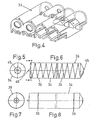
- Each reactor 8 is constituted by an enveloping external chamber 33, see FIGS. 4 and 9, and by an internal cylindrical reactor body 34, shown in FIGS. 5 to 8.
- the outer chamber 33 consists of refractory bricks, and in the space between the outer chamber 33 and the corresponding inner cylindrical body, there are located heating means such as in particular mixed gas and heavy fuel oil burners 27, which serve to raise the temperature of the air chamber which surrounds the cylindrical body 34, so that the latter receives heat in a homogeneous and indirect manner and which in particular allow a working temperature inside the body 34 reaching a value between 400 and 600 ° C.
- heating means such as in particular mixed gas and heavy fuel oil burners 27, which serve to raise the temperature of the air chamber which surrounds the cylindrical body 34, so that the latter receives heat in a homogeneous and indirect manner and which in particular allow a working temperature inside the body 34 reaching a value between 400 and 600 ° C.
- each cylindrical body 34 according to a non-limiting practical embodiment, to consist of a stainless steel cylinder approximately eight meters long by two and a half meters in diameter, which can thus receive a load of the order of seven tonnes of residues to be processed.
- each cylindrical body 34 Inside each cylindrical body 34 are helically disposed deflection fins 35, see FIG. 6, the mission of which is to move and distribute the load homogeneously throughout the interior of the body 34 of each reactor 8.
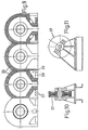
- Each cylindrical body 34 is capable of carrying out a radial rotational movement on itself, movement obtained by wheels 37 shown in FIGS. 10 and 11, which are supported on rolling tracks 36.
- These wheels 37 are mounted in frames installed on supports 38, which are arranged in enclosures 39 located outside the heating chamber defined between each cylindrical body 34 and its covering of refractory material 33 as can be seen in the figure 9.
- the arrangement of the wheels 37 in these enclosures 39 allows the wheels 37 not to be subjected to high temperatures during work.
- the rotation of the cylindrical bodies 34 can be carried out at two different speed regimes, one fast loading and unloading and the other slow working.
- the transmission is carried out by a reduction motor and a chain, and it is equipped with an intermediate tensioner to compensate for expansions.
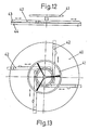
- the loading and unloading is carried out through a mouth 45 located at the front part of the reactor.
- This mouth 45 has a door 40, see Figures 12 and 13 which can be closed by a rotary flywheel device 41, with which mesh racks 42 which can thus occupy two positions, one of introduction which allows the opening of the door 40 and the other exit which prevents this opening.
- the racks 42 have wedge-shaped ends 43 which tend to push on the door 40 in the direction of its closing.
- the door 40 has a graphite seal 44 to ensure a hermetic closure.
- each body 34 On the rear part of each body 34 there is a mouth 46 for the coupling of the gas extraction pipe, provided with a rotary connector whose sealing is ensured by a cable gland.
- filtering means for large solid elements which are intended to prevent their exit through the gas discharge pipe. These filtering means are cleaned automatically by the friction of the residues.
- a filtering device 47 for particles possibly suspended in the gas, which are retained by their impact against a series of deflection blades.
- deflection blades 48 pass through grooves, formed for this purpose in a plate 49 mounted on a timed pneumatic piston 50, which performs at predetermined time intervals a movement back and forth along the blades 48 to clean them.
- each filter 47 there is a tilting cover 51, the selective opening of which allows the dust deposited inside each filter 47 to be quickly emptied.
- the body 34 of each reactor 8 is provided with a cooling device, which, taking the water condensed in the system, injects it inside the bodies 34 during the final phase of cooling the product, and this water which evaporates instantly creates a refrigeration which continues until reaching the established temperature, of the order of 100 degrees Centigrade which avoids the possibility of fire or explosion during discharge.
- the extracted gas continues its journey to tar condensing means 18, in which the gas is cooled below 140 ° C. by a counter-current circulation of water which is automatically controlled by a solenoid valve provided with a thermostat.
- Each tar condenser 18 is provided with an individual tank 19, and all these individual tanks are connected to a common feed tank 20.
- the gas from the condensers 18 arrives at the water condensers 21 at a temperature of the order of 140 ° C. and it is cooled by a circulation of water against the current below 40 ° C; in this way all the aqueous fraction which is collected in the individual reservoirs 22 is condensed.
- the individual tanks 22 communicate with a common tank 23, and as in the previous case, they can be separated individually from this common tank 23, from which, by means of a motor pump, the water is passed through devices filtering and treatment for later use or discharge.
- Figure 1 we can see the system 30 for primary water purification, formed by six columns filled with vegetable charcoal and which act in two stages, that is to say a step of roughing and filtering of scum and a step finishing, after which the water enters swimming pools or cooling water tanks 31 arranged in series to cool the water.
- the excess water is sent to a final treatment group 32 formed by two parallel columns filled with activated carbon, in which the possible residues of organic solvents are absorbed, after which the water arrives at an additional treatment box in which is carried out a disinfection and an oxidation by bubbling gaseous chlorine and air, and the water then passes again through the columns of activated carbon in order to retain the residual chlorine, the chloromines and the other chemical components which could have formed.
- the effluent is treated in the annex tank by means of automatic neutralization operations, pH and temperature control, after which it is discharged.
- the fraction of gas not condensed in the condensers 21 is led to a gas washer 24 in which it is washed by bubbling in two phases: first with a strongly basic fluid and then with a strongly acidic fluid. In this way, the non-condensable components of an acidic or basic character are retained.
- the gas washing is completed by the cyclone effect produced on the water by the liquid vacuum pump ring 25.
- each reactor 8 and more precisely each reactor body 34 is connected to means which allow the process of thermal transformer of the residues to take place under vacuum and is subject to a set of vacuum pumps 25.
- the treatment efficiency is increased thanks to the vacuum and it is possible to carry out the treatment at a lower temperature without affecting the yield.
- These vacuum pumps 25 are two pumps of the liquid ring type, arranged symmetrically and which operate in a staggered fashion, in order to adapt the suction capacity at any time to the flow rate of gas produced. These pumps 25 thus create a vacuum in which the entire circuit operates, a vacuum which gives rise to the suction of the gaseous phase coming from the reactors 8.
- the reference numbers 26 and 26′ indicate two gas tanks, a small tank 26 intended for the recirculation of the gas which must be burned in the burners 27, and a larger tank 26 ′ which serves reserve for the initial phase during which a sufficient quantity of gas is not produced for self-supply and for the final phase, in which more gas is produced than is consumed.
- the large tank 26 ′ is fitted with a safety device which, in the event of overpressure, causes the opening of a valve as well as the ignition of a torch, and in addition there is an automatic cooling system by watering.
- the body 34 rotates in the opposite direction to that of the loading, so that the fins 35 move the product towards the mouth 45.
- a mobile pneumatic extraction bell 9 which sucks the solid particles of carbon in suspension. These particles are transported to a mill 13 to be finely divided.
- the portion of non-pneumatically captured carbonized material is deposited on a conveyor belt 10, which transports it to a hopper 11 which receives the product, for the subsequent feeding of a vibrating screen 12, in which the ferromagnetic elements, the elements are separated. inert and other metals.
- the charred product which passes through the meshes of the screen 12 is transported pneumatically to the hopper of the mill 13.
- the micronizer mill 13 receives the charred material coming from two different points, which are: the pneumatic capture system 9 and the screen 12.
- the mill 13 includes a device for separating a large part of the ash, and reduces the dimensions of the particles below 75 microns .
- a filter 15 is installed which performs the following two functions: on the one hand it filters the dust collected by the pneumatic sensor 9 during unloading, and on the other hand it filters the current entrained by the mill 13.
- the product collected in the cyclone 14 and in the filter 15 arrives at a scale-bagger 16 in which it is automatically bagged so that it can be handled, stored and marketed in a more perfect and cleaner manner.
- the most common industrial residues are plastics, rubber, tires, wood and upholstery, etc. After having crushed all these residues in the machine 6, they are introduced into the corresponding reactor or reactors 8, by switching on their respective burners 27, and then connecting the vacuum pipe obtained by the motor pumps 25.
- the various reactions take place as the temperature increases, which gives rise to the formation of gases of different characteristics, the tar gases condensing in the condensers 18.
- the tar thus obtained is a complex mixture of aromatic compounds , which in subsequent operations can be distilled to obtain different solvents.
- the non-condensable gases are washed at 24 and are stored in the tanks 26 and 26 ′ to supply the burners 27 with them.
- the product is led, by means of the pneumatic sensor 9 and the strip 10 to the area of the mill 13 and it finally arrives at the weighing machine 16.
- Ferromagnetic products such as cans
- Ferromagnetic products are then added to the crushed residues and the whole is introduced into the reactors 8, since it has been shown that the tin with which the cans are provided helps to absorb chlorine which occurs during reactions inside the reactors 8.
- the agricultural and forestry residues are treated by introducing them into a kind of cutting machine equipped with knives to reduce their dimensions, after which they are led directly by the strips 7 to the reactor 8, in which the thermal reaction takes place.
- the entire product is constituted by carbonized material, since this material contains only fixed carbon, volatile elements and between 0.5 and 0.7% of sulfur, with a reduced percentage of 6-8 % of ash, which is almost completely separated in the mill 13.
- the products obtained are applicable to different industries and therefore the smoke black can be used in the rubber and plastic industries.
- Coal for injection is very successful as a fuel in the cement, ceramic and other industries and it can also be used to transform it into briquettes used in heating boilers.
- Tar can be used in different ways: because of its composition it could be used as liquid fuel (medium density fuel) it can be distilled to extract the solvents it contains for use in industry, while the rest can be used as a waterproofing agent or in the form of agglomerated tar to cover the floor.
Landscapes
- Chemical & Material Sciences (AREA)
- Engineering & Computer Science (AREA)
- Oil, Petroleum & Natural Gas (AREA)
- Organic Chemistry (AREA)
- Materials Engineering (AREA)
- Combustion & Propulsion (AREA)
- Processing Of Solid Wastes (AREA)
- Processing And Handling Of Plastics And Other Materials For Molding In General (AREA)
- Electrical Discharge Machining, Electrochemical Machining, And Combined Machining (AREA)
- Liquid Developers In Electrophotography (AREA)
- Signal Processing For Digital Recording And Reproducing (AREA)
- Waste-Gas Treatment And Other Accessory Devices For Furnaces (AREA)
Abstract
Description
La présente invention est relative à un dispositif pour la transformation de résidus. Le document FR-A-2 277 137 décrit un tel dispositif.The present invention relates to a device for the transformation of residues. Document FR-A-2 277 137 describes such a device.
Le problème mondial des résidus s'accentue chaque jour toujours plus, en raison des immenses quantités produites, tant dans le domaine industriel que dans le domaine rural et dans le domaine urbain, leur destruction donnant lieu à un problème trés important.The world problem of residues is getting worse every day, because of the immense quantities produced, in the industrial as well as in the rural and urban areas, their destruction giving rise to a very important problem.
Jusqu'à une date assez récente, la forme la plus habituelle d'élimination des résidus à consisté à les décharger sur des emplacements prévus à cet effet. Par la suite, ce système de simple décharge, toujours en vigueur en grande partie a été amélioré ou a été abandonné pour passer à d'autres systèmes, et par conséquent, actuellement les différents systèmes d'élimination des résidus peuvent être classés dans les modalités suivantes, à savoir : les décharges contrôlées, les systèmes de traitement mixte, les systèmes de traitement mixte et "compost", les systèmes de traitement par incinération sans récupération ou avec récupération d'énergie, et enfin les systèmes de traitement par pyrolyse.Until fairly recently, the most common form of waste disposal has been to dispose of them in designated areas. Subsequently, this simple discharge system, which is still largely in force, has been improved or has been abandoned to switch to other systems, and therefore, currently the various residue disposal systems can be classified in the modalities. following, namely: controlled landfills, mixed treatment systems, mixed and "compost" treatment systems, incineration treatment systems without recovery or with energy recovery, and finally pyrolysis treatment systems.
Dans les systèmes à décharge contrôlée, traitement mixte, traitement mixte et "compost", les inconvénients sont nombreux et résident essentiellement en des inconvénients d'environnement et d'exploitation.In systems with controlled discharge, mixed treatment, mixed treatment and "compost", the drawbacks are numerous and lie mainly in environmental and operational drawbacks.
Pour pallier ces inconvénients, les systèmes de traitement par incinération avec ou sans récupération permettent un traitement plus industriel des résidus.To overcome these drawbacks, incineration treatment systems with or without recovery allow a more industrial treatment of residues.
Cependant, lors de l'incinération des résidus sans récupération, il est généralement constaté des contaminations atmosphériques importantes et le coût d'exploitation et d'entretien est élevé du fait de la non récupération.However, during incineration of residues without recovery, it is generally observed that there is significant atmospheric contamination and the cost of operation and maintenance is high due to the non-recovery.
Dans les systèmes de traitement par incinération avec récupération d'énergie, on incinère les résidus dans un four et on récupère l'énergie produite par la combustion des résidus.In incineration treatment systems with energy recovery, the residues are incinerated in an oven and the energy produced by the combustion of the residues is recovered.
La chaleur récupérée est utilisable par exemple, pour obtenir de la vapeur, de l'eau chaude pour le chauffage, pour produire de l'énergie électrique, etc...The recovered heat can be used for example, to obtain steam, hot water for heating, to produce electrical energy, etc.
En pratique, cette utilisation est très coûteuse car l'énergie obtenue doit être canalisée jusqu'à son point d'utilisation.In practice, this use is very expensive because the energy obtained must be channeled to its point of use.
Cela étant, dans le but de pallier les différents inconvénients précités, un dernier type de traitement s'est développé, il s'agit du traitement par pyrolyse, appelé aussi pyrodécomposition, qui consiste à séparer d'une substance d'autres substances plus simples, au moins d'un apport de chaleur.However, in order to overcome the various drawbacks mentioned above, a last type of treatment has developed, this is treatment by pyrolysis, also called pyrodecomposition, which consists in separating a substance from other simpler substances , at least of a contribution of heat.
En principe, ce genre de traitement est celui qui peut présenter les plus grands avantages, du fait qu'il agit sur toutes les matières susceptibles d'être dégradées thermiquement, bien que jusqu'à présent on n'ait pas obtenu de résultats satisfaisants.In principle, this kind of treatment is the one which can have the greatest advantages, since it acts on all the materials liable to be thermally degraded, although so far satisfactory results have not been obtained.
L'étude de ces résultats négatifs effectuée par l'inventeur du présent brevet, l'a conduit à conclure que ces résultats sont dus à un choix erroné des conditions de travail, et fondamentalement de la température choisie pour le traitement.The study of these negative results carried out by the inventor of the present patent, led him to conclude that these results are due to an incorrect choice of the working conditions, and basically of the temperature chosen for the treatment.
A cet effet, on a choisi une température comprise entre 1000 et 1500°C, ce qui donne lieu à de grandes difficultés techniques tant pour le choix des équipements que pour leur fonctionnement, et ce qui a conduit également à des couts trés élevés.For this purpose, a temperature of between 1000 and 1500 ° C. has been chosen, which gives rise to great technical difficulties both for the choice of the equipment and for its operation, and which also leads to very high costs.
L'objet de la présente invention est de proposer un dispositif de traitement de résidus, tel que caractérisé dans les revendications, qui, dans le cadre des traitements par "pyrolyse", permette de pallier les inconvénients précités et apporte une solution au problème des traitements connus dans ce domaine, de façon à obtenir une transformation des résidus dans des conditions réellement optimales comme on pourra le voir plus loin.The object of the present invention is to provide a device for treating residues, as characterized in the claims, which, in the context of "pyrolysis" treatments, makes it possible to overcome the aforementioned drawbacks and provides a solution to the problem of treatments. known in this field, so as to obtain a transformation of the residues under truly optimal conditions as will be seen below.
Le dispositif qui constitue l'objet de la présente invention présente les objectifs de base suivants :
- .- L'utilisation de réacteurs thermique qui, en raison de leur principe de construction et de la conception de l'ensemble de l'installation, permettent de faire fonctionner le système à une température réduite, par rapport à tous les procédés de "pyrolyse" connus jusqu'à présent.
- .- La température de travail maximale, en tenant compte des fluctuations normales en fonction des caractéristiques des résidus à traiter, est compriseentre 400 et 600°C.
- .- La conception d'un dispositif dont le principe essentiel est identique peur la transformation de résidus, tant industriels qu'urbains ou ruraux, dans lequel seules varient les conditions de travail en ce qui concerne la température, les catalyseurs et autres substances qui donnent lieu à la formation de différentes réactions chimiques en fonction des types de résidus à traiter.
- .- La réalisation d'un dispositif modulaire, de façon que chaque réacteur thermique, avec son équipement correspondant puisse travailler individuellement, ce qui permet d'utiliser dans un système qui présente la même conception, depuis un seul réacteur jusqu'à une ou plusieurs batteries de réacteurs.
- .- The use of thermal reactors which, because of their construction principle and the design of the whole installation, allow the system to operate at a reduced temperature, compared to all "pyrolysis" processes. "known so far.
- .- The maximum working temperature, taking into account normal fluctuations depending on the characteristics of the residues to be treated, is between 400 and 600 ° C.
- .- The design of a device whose essential principle is identical fear the transformation of residues, as industrial as urban or rural, in which only vary the working conditions with regard to temperature, catalysts and other substances which give lead to the formation of different chemical reactions depending on the types of residue to be treated.
- .- The realization of a modular device, so that each thermal reactor, with its corresponding equipment can work individually, which allows to use in a system that has the same design, from a single reactor to one or more reactor batteries.
En accord avec ces conditions, le dispositif qui constitue l'objet de la présente invention présente les avantages suivants:
- .- Le dispositif est applicable à toutes quantités de résidus, car le caractère modulaire du dispositif permet de travailler en utilisant depuis un seul réacteur, jusqu'à une ou plusieurs batteries de réacteur, et par conséquent ce dispositif peut être installé pour transformer les résidus provenant d'une usine, d'un village ou même d'une ville plus importante.
- .- Il ne produit aucune contamination par de l'eau ou par des gaz de combustion, car l'eau est traitée de façon adéquate avant d'être déchargée, et les gaz sont lavés chimiquement avant la combustion.
- .- La sélection préalable est facultative, mais elle n'est pas indispensable, car il estpossible d'introduire l'ensemble des résidus dans le réacteur, et par conséquent, dans les installations de capacité réduite, cette sélection n'est pas nécessaire.
- .- Ce dispositif permet de transformer les résidus en produits de grande consommation et de commercialisation facile, et par conséquent ce système est rentable à partir d'une certaine quantité, ce qui fait que son coût est facilement amortissable.
- .- Les coûts d'installation et de fonctionnement sont réduit par rapport aux autres systèmes existants.
- .- Dans ce dispositif les résidus, à partir du moment de leur reception, sont traités dans un bâtiment fermé, et par conséquent l'installation peut être située dans n'importe quel environnement industriel proche du noyau de population producteur de résidus, ce qui se traduit par une grande économie de transport de ces résidus.
- .- Le fait que chaque réacteur avec son équipement constitue un module fonctionnel qui peut être indépendant, permet que les pannes ou les travaux d'entretien ne paralysent que le réacteur ou les réacteurs nécessaires, l'installation continuant à fonctionner.
- .- The device is applicable to all quantities of residues, because the modular nature of the device makes it possible to work using from a single reactor, to one or more reactor batteries, and therefore this device can be installed to transform the residues from a factory, a village or even a larger city.
- .- It does not produce any contamination by water or by combustion gases, because the water is adequately treated before being discharged, and the gases are washed chemically before combustion.
- .- The prior selection is optional, but it is not essential, since it is possible to introduce all the residues into the reactor, and therefore, in installations with reduced capacity, this selection is not necessary.
- .- This device makes it possible to transform the residues into products of great consumption and easy marketing, and consequently this system is profitable from a certain quantity, which means that its cost is easily amortized.
- .- Installation and operating costs are reduced compared to other existing systems.
- .- In this device the residues, from the moment of their reception, are treated in a closed building, and consequently the installation can be located in any industrial environment close to the nucleus of population producing residues, which results in a great saving in transport of these residues.
- .- The fact that each reactor with its equipment constitutes a functional module which can be independent, allows breakdowns or maintenance work to paralyze only the necessary reactor or reactors, the installation continuing to operate.
Toutes ces améliorations, ainsi que d'autres qui apparaîtront de façon plus détaillée dans cette description, dotent le présent dispositif d'un caractère différent de tout ce qui est connu jusqu'à présent.All these improvements, as well as others which will appear in more detail in this description, endow the present device with a character different from all that is known up to now.
Pour faciliter la compréhension de la nature de la présente invention, dans les dessins ci-joints il est représenté, à titre d'exemple purement illustratif et non limitatif, une forme avantageuse de réalisation industrielle, et dans les dessins en question:
- La figure 1 représente schématiquement, une installation qui correspond à un exemple possible non limitatif de réalisation de l'invention.
- La figure 2 représente une vue en élévation d'une installation selon le schéma de la figure 1.
- La figure 3 correspond à une vue en plan de la partie supérieure de la figure précédente, parciellement en coupe.
- La figure 4 représente en perspective et de façon schématique quatre chambres extérieures 33 d'un même nombre de
réacteurs 8. - La figure 5 correspond à la coupe V-V indiquée dans la figure 6 dans le cas où cette dernière serait une vue non sectionnée.
- La figure 6 représente une coupe longitudinale du corps cylindrique 34 de chaque
réacteur 8. - La figure 7 représente une vue en profil de la figure 8.
- La figure 8 est une vue en élévation du
corps 34. - La figure 9 est une vue de face partiellement en coupe des quatre chambres extérieures 33 que l'on voit dans la figure 4.
- Les figures 10 et 11 représentent l'une des
roues 37 avec son armature de support ainsi que des vues en profil et en élévation respectivement dont la première est représentée partiellement en coupe. - La figure 12 est une vue en élévation de la figure 13.
- La figure 13 représente en plan, l'une des
portes 40 de la bouche de chargement et dedéchargement 45 des corps cylindriques métalliques 34. - La figure 14 représente la coupe XIV-XIV indiquée dans la figure 15.
- La figure 15 est une vue en élévation d'un
filtre 47 dont la partie extérieure est représentée en lignede tracé mixte.
- FIG. 1 schematically represents an installation which corresponds to a possible nonlimiting example of embodiment of the invention.
- FIG. 2 represents an elevation view of an installation according to the diagram of FIG. 1.
- Figure 3 corresponds to a plan view of the upper part of the previous figure, partially in section.
- FIG. 4 shows in perspective and schematically four
external chambers 33 of the same number ofreactors 8. - Figure 5 corresponds to the section VV indicated in Figure 6 in the case where the latter would be a non-sectioned view.
- FIG. 6 represents a longitudinal section of the
cylindrical body 34 of eachreactor 8. - FIG. 7 represents a profile view of FIG. 8.
- FIG. 8 is an elevation view of the
body 34. - FIG. 9 is a partially sectioned front view of the four
external chambers 33 which can be seen in FIG. 4. - Figures 10 and 11 show one of the
wheels 37 with its support frame and views in profile and in elevation respectively, the first of which is shown partially in section. - FIG. 12 is an elevation view of FIG. 13.
- FIG. 13 shows in plan, one of the
doors 40 of the loading and unloadingmouth 45 of the metalliccylindrical bodies 34. - Figure 14 shows the section XIV-XIV shown in Figure 15.
- Figure 15 is an elevational view of a
filter 47, the outer part of which is shown in a mixed line.
Le système qui constitue l'objet de la présente invention a pour but la transformation de résidus, tant industriels que ruraux et urbains, et l'on a représenté dans la figure 1 de façon schématique un exemple possible d'une installation pratique de ce système de transformation, dont la description générale en ce qui concerne les moyens qui le constituent est la suivante:
Dans un bâtiment général fermé, dans lequel est installée la réception des résidus est située une trémie de réception 1 qui est alimentée par une pince à griffes ou par d'autres moyens analogues. Dans la partie inférieure de la trémie 1 il existe un dispositif de rupture formé par des files de cylindres tournants qui comportent sur leur périphérie une série de pointes coniques disposées de telle façon qu'elles rompent les sacs contenant les ordures et laissent passer librement les bouteilles de verre.The system which constitutes the object of the present invention aims to transform residues, both industrial, rural and urban, and there is shown in Figure 1 schematically a possible example of a practical installation of this system. of transformation, whose general description as regards the means which constitute it is as follows:
In a general closed building, in which the reception of residues is installed, there is a reception hopper 1 which is supplied by a claw pliers or by other similar means. In the lower part of the hopper 1 there is a breaking device formed by rows of rotating cylinders which have on their periphery a series of conical points arranged in such a way that they break the bags containing the refuse and allow the bottles to pass freely of glass.
En face de la trémie est disposé une bande transporteuse 2 qui traverse une zone 3, destinée à la selection du verre, et éventuellement de la matière plastique, zone dans laquelle peuvent être séparés des résidus, des objets de verre et éventuellement de matière plastique.In front of the hopper is arranged a conveyor belt 2 which passes through a
A la fin de la bande 2 est disposée une unité 4 de capture magnétique formée par un cylindre magnétique qui sépare des résidus la fraction ferro-magnétique. Cette fraction ferro-magnétique tombe par la suite sur une nouvelle bande transporteuse 7 et elle se mélange de nouveau avec les résidus qui ont été triturés préalablement dans un broyeur 5, dans le but de réduire leur volume et de pouvoir mettre à profit de cette façon la capacité maxima des réacteurs thermiques 8.At the end of the strip 2 is arranged a
En face de la bande transporteuse7 est disposée une autre unité de broyage 6, pour les pneumatiques, la biomasse ou pour d'autres types de résidus adaptables au processus et qui sont différents des résidus urbains connus sous le nom d'ordures.In front of the conveyor belt 7 is arranged another grinding
Dans le cas où l'installation est équipée d'un seul réacteur 8, la bande 7 se prolonge jusqu'à la bouche de chargement de ce dernier; cependant, lorsqu' il existe plusieurs réacteurs 8 on a prévu que la bande 7 soit constitué par une partie fixe et une partie finale mobile, au moyen de laquelle on chargera les résidus dans la bouche du réacteur 8 correspondant.In the case where the installation is equipped with a
Chaque réacteur 8 est constitué par une chambre extérieure enveloppante 33, voir figures 4 et 9, et par un corps de réacteur cylindrique intérieur 34, représenté dans les figures 5 à 8.Each
La chambre extérieure 33 est constituée par des briques réfractaires, et dans l'espace compris entre la chambre extérieure 33 et le corps cylindrique intérieur correspondant, sont situés des moyens de chauffage tels que notamment des brûleurs mixtes 27 à gaz et à fuel lourd, qui servent à élever la température de la chambre à air qui entoure le corps cylindrique 34, de façon que ce dernier reçoive la chaleur de façon homogène et indirecte et qui autorisent notamment une température de travail à l'intérieur du corps 34 atteignant une valeur comprise entre 400 et 600°C.The
Il a été prévu que chaque corps cylindrique 34, selon une réalisation pratique non limitative soit constitué par un cylindre d'acier inoxydable d'environ huit mètres de long par deux mètres et demi de diamètre, qui peut ainsi recevoir un chargement de l'ordre de sept tonnes de résidus à transformer.Provision has been made for each
A l'intérieur de chaque corps cylindrique 34 sont disposés hélicoïdalement des ailettes de déflection 35, voir figure 6, dont la mission consiste à déplacer et distribuer la charge de façon homogène dans tout l'intérieur du corps 34 de chaque réacteur 8.Inside each
Chaque corps cylindrique 34 est susceptible de réaliser sur lui même un mouvement de rotation radial, mouvement obtenu par des roues 37 représentées dans les figures 10 et 11, qui s'appuient sur des pistes de roulement 36.Each
Ces roues 37 sont montées dans des bâtis installés sur des supports 38, qui sont disposés dans des enceintes 39 situées en dehors de la chambre de chauffage définie entre chaque corps cylindrique 34 et son recouvrement de matériau réfractaire 33 comme on peut le voir dans la figure 9. La disposition des roues 37 dans ces enceintes 39 permet que les roues 37 ne soient pas soumises à des températues élevées pendant le travail.These
La rotation des corps cylindriques 34 peut s'effectuer à deux régimes de vitesse différents, l'un rapide de chargement et de déchargement et l'autre lent de travail. La transmission est effectué par un moteur réducteur et une chaine, et elle est dotée d'un tendeur intermédiaire pour compenser les dilatations.The rotation of the
Le chargement et le déchargement s'effectuent à travers une bouche 45 située à la partie avant du réacteur. Cette bouche 45 présente une porte 40, voir figures 12 et 13 qui peut être fermée par un dispositif de volant tournant 41, avec lequel engrènent des crémaillères 42 qui peuvent occuper ainsi deux positions, l'une d'introduction qui permet l'ouverture de la porte 40 et l'autre de sortie qui empêche cette ouverture. Les crémaillères 42 présentent des extrémités en forme de coin 43 qui tendent à exercer une poussée sur la porte 40 dans le sens de sa fermeture. Egalement, la porte 40 présente un joint de graphite 44 pour assurer une fermeture hermétique.The loading and unloading is carried out through a
Sur la partie postérieure de chaque corps 34 il existe une bouche 46 pour l'accouplement du tuyau d'extraction des gaz, dotée d'un raccord tournant dont l'étanchéité est assurée par un presse-étoupe.On the rear part of each
A l'intérieur et sur la partie postérieure ou de sortie des gaz sont situés des moyens de filtrage pour les éléments solides de grande dimension qui sont destinés à empêcher leur sortie par le tuyau d'évacuation des gaz. Ces moyens de filtrage sont nettoyés automatiquement par la friction des résidus.Inside and on the rear or outlet side of the gases are located filtering means for large solid elements which are intended to prevent their exit through the gas discharge pipe. These filtering means are cleaned automatically by the friction of the residues.
Dans le tube d'extraction des gaz, à la sortie du réacteur, est situé un dispositif de filtrage 47 des particules éventuellement en suspension dans le gaz, qui sont retenues par leur choc contre une série de lames de déflection.In the gas extraction tube, at the outlet of the reactor, is located a
Dans les figures 14 et 15 on a représenté un exemple de réalisation pratique possible des filtres en question 47, dans lequel chacun d'eux présente une pluralité de lames de déflection 48, qui sont disposées en quinconce.In Figures 14 and 15 there is shown a possible practical embodiment of the filters in
Ces lames de déflection 48 passent à travers des rainures, formées à cet effet dans une plaque 49 montée sur un piston pneumatique temporisé 50, lequel effectue à intervalles de temps prédéterminés un mouvement de va et vient le long des lames 48 pour les nettoyer.These
A la base de chaque filtre 47 il existe un couvercle basculant 51, dont l'ouverture sélective permet de vider rapidement la poussière déposée à l'intérieur de chaque filtre 47.At the base of each
D'autre part, le corps 34 de chaque réacteur 8 est pourvu d'un dispositif réfrigérant, qui, prenant l'eau condensée dans le système, l'injecte à l'intérieur des corps 34 pendant la phase finale de refroidissement du produit, et cette eau qui s'évapore instantanément crée une réfrigération qui continue jusqu'à atteindre la température établie, de l'ordre de 100 degrès Centigrades ce qui évite la possibilité d'incendie ou d'explosion durant la décharge.On the other hand, the
Le gaz qui est extrait pendant le fonctionnement de chaque réacteur 8 et qui arrive à atteindre, à la sortie du réacteur, une température de 600°C, traverse après avoir été filtré, un échangeur de chaleur 17 qui le refroidit partiellement, cette chaleur étant absorbée par le gaz d'alimentation du brûleur 27, et le gaz se trouvant ainsi dans des conditions excellentes pour être brûlé.The gas which is extracted during the operation of each
Le gaz extrait poursuit son parcours jusqu'à des moyens condenseurs de goudron 18, dans lesquels le gaz est refroidi au-dessous de 140°C par une circulation d'eau à contre-courant qui est contrôlée automatiquement par une électrovanne pourvue d'un thermostat.The extracted gas continues its journey to tar condensing means 18, in which the gas is cooled below 140 ° C. by a counter-current circulation of water which is automatically controlled by a solenoid valve provided with a thermostat.
Chaque condenseur de goudron 18 est doté d'un réservoir individuel 19, et tous ces réservoirs individuels sont reliés à un réservoir nourrice commun 20.Each
Lorsque l'on vide le réservoir 20, on ferme les vannes entre ce dernier et les réservoirs individuels 19 et l'on met en marche une pompe d'évacuation du goudron vers un réservoir extérieur de magasinage, cette opération pouvant être effectuée sans affecter d'aucune façon le vide dans la conduite.When the
Le gaz provenant des condenseurs 18 arrive à des condenseurs d'eau 21 à une température de l'ordre de 140°C et il est refroidi par une circulation d'eau à contre-courant au-dessous de 40°C; de cette façon on condense toute la fraction aqueuse qui est recueillie dans les réservoirs individuels 22.The gas from the
Les réservoirs indivuels 22 communiquent avec un réservoir commun 23, et comme dans le cas précédent, ils peuvent être séparés indivuellement de ce réservoir commun 23, à partir duquel, au moyen d'une motopompe, on fait passer l'eau à travers des dispositifs de filtrage et de traitement pour son utilisation ultérieure ou sa décharge.The
Dans la figure 1 on peut voir le système 30 de dépuration primaire de l'eau, formé par six colonnes remplies de charbon végétal et qui agissent en deux étapes, c'est à dire une étape de dégrossissage et de filtrage des écumes et une étape de finition, aprés quoi l'eau pénètre dans des piscines ou dans des réservoirs d'eau de refroidissement 31 disposés en série pour refroidir l'eau.In Figure 1 we can see the
L'excédent d'eau est envoyé à un groupe de traitement final 32 formé par deux colonnes en paralléle remplies de charbon actif, dans lesquelles sont absorbés les résidus possibles de solvants organiques, après quoi l'eau arrive à un caisson annexe de traitement dans lequel est effectuée une désinfection et une oxydation au moyen d'un barbotage de chlore gazeux et d'air, et l'eau traverse ensuite de nouveau les colonnes de charbon actif afin de retenir le chlore résiduel, les chloromines et les autres composants chimiques qui auraient pu se former. L'effluent est traité dans le caisson annexe au moyen d'opérations automatiques de neutralisation, contrôle du pH et température, après quoi il est évacué.The excess water is sent to a
La fraction de gaz non condensée dans les condenseurs 21 est conduite à un laveur de gaz 24 dans lequel elle est lavé par barbotage en deux phases: en premier lieu avec un fluide fortement basique et ensuite avec un fluide fortement acide. De cette façon on retient les composants non condensables de caractère acide ou basique. Le lavage de gaz est complété par l'effet de cyclone réalisé sur l'eau par l'anneau liquide de pompe à vide 25.The fraction of gas not condensed in the
A cet égard, chaque réacteur 8 et plus précisément chaque corps 34 de réacteur est relié à des moyens qui permettent que le processus de transformateur thermique des résidus se déroule sous vide et est assujetti à un ensemble de pompes à vide 25. Ainsi, l'efficacité du traitement est accrue grâce au vide et il est possible d'effectuer le traitement à plus basse température sans influence sur le rendement.In this respect, each
Ces pompes à vide 25 sont deux pompes du type d'anneau liquide, disposées symétriquement et qui fonctionnent de façon échelonnée, pour adapter à tout moment la capacité d'aspiration au débit de gaz produit. Ces pompes 25 créent ainsi un vide dans lequel fonctionne tout le circuit, vide qui donne lieu à l'aspiration de la phase gazeuse provenant des réacteurs 8.These vacuum pumps 25 are two pumps of the liquid ring type, arranged symmetrically and which operate in a staggered fashion, in order to adapt the suction capacity at any time to the flow rate of gas produced. These pumps 25 thus create a vacuum in which the entire circuit operates, a vacuum which gives rise to the suction of the gaseous phase coming from the
Dans la figure 1 on peut voir que les numéros de référence 26 et 26′indiquent deux réservoirs de gaz, un petit réservoir 26 destiné à la recirculation du gaz qui doit être brûlé dans les brûleurs 27, et un réservoir plus grand 26′ qui sert de réserve pour la phase initiale durant laquelle il n'est pas produit une quantité de gaz suffisante pour l'auto-alimentation et pour la phase finale, dans laquelle il est produit plus de gaz que l'on n'en consomme.In Figure 1 we can see that the
Le réservoir de grande dimension 26′ est doté d'un dispositif de sécurité qui, en cas de surpression, provoque l'ouverture d'une vanne ainsi que l'allumage d'une torche, et en outre il existe un système de refroidissement automatique par arrosage.The
Lorsque la pression du gaz dans les petits réservoirs 26 dépasse une valeur prédéterminée un compresseur 29 se met en marche automatiquement et donne lieu au transfert de ce gaz au réservoir de grandes dimensions 26′.When the pressure of the gas in the
Une fois terminé le travail du réacteur ou des réacteurs 8 correspondants, le corps 34 tourne dans le sens contraire à celui du chargement, de façon que les ailettes 35 déplacent le produit vers la bouche 45.Once the work of the corresponding reactor or
A cette bouche 45 est reliée, pendant la décharge, une cloche mobile d'extraction pneumatique 9 qui aspire les particules solides de charbon en suspension. Ces particules sont transportées à un moulin 13 pour être divisées finement.To this
La partie de matière carbonisée non captée pneumatiquement est déposée sur une bande transporteuse 10, qui la transporte vers une trémie 11 qui reçoit le produit, pour l'alimentation ultérieure d'un crible vibrant 12, dans lequel sont séparés les éléments ferromagnétiques, les éléments inertes et les autres métaux. Le produit carbonisé qui traverse les mailles du crible 12 est transporté pneumatiquement jusqu'à la trémie du moulin 13.The portion of non-pneumatically captured carbonized material is deposited on a
Le reste continue jusqu'à la fin de la ligne de criblage où sont séparés magnétiquement les métaux ferromagnétiques pour être comprimés et commercialisés ultérieurement. Les autres éléments inertes sont recueillis dans un petit réservoir pour être déchargés ultérieurement.The rest continues until the end of the screening line where the ferromagnetic metals are separated magnetically to be compressed and marketed later. The other inert elements are collected in a small tank for later discharge.
De cette façon, le moulin microniseur 13 reçoit la matière carbonisée provenant de deux points différents, lesquels sont: le système de capture pneumatique 9 et le crible 12. Le moulin 13 comporte un dispositif de séparation d'une grande partie des cendres, et réduit les dimensions des particules au-dessous de 75 microns.In this way, the
A sa sortie du moulin 13, le produit arrive à un cyclone 14 dans lequel est effectuée la décantation du produit moulu. Conjointement avec le cyclone 14 est installé un filtre 15 qui réalise les deux fonctions suivantes: d'une part il filtre la poussière recueillie par le capteur pneumatique 9 pendant le déchargement, et d'autre part il filtre le courant entrainé par le moulin 13.On leaving the
Finalement, le produit recueilli dans le cyclone 14 et dans le filtre 15 arrive à une bascule-ensacheuse 16 dans laquelle il est mis en sac automatiquement pour qu'il puisse être manipulé, magasiné et commercialisé de façon plus parfaite et plus propre.Finally, the product collected in the
Après avoir décrit les moyens fondamentaux utilisés dans l'installation en accord avec le système qui constitue l'objet de l'invention, on décrira dans ce qui suit le fonctionnement de ces moyens pour la transformation des trois types de résidus mentionnés, c'est à dire résidus industriels, urbains et ruraux.After having described the fundamental means used in the installation in accordance with the system which constitutes the object of the invention, the following will describe the operation of these means for the transformation of the three types of residues mentioned, it is ie industrial, urban and rural residues.
Les résidus industriels les plus communs sont les plastiques, les caoutchouc, les pneumatiques, les restes de bois et de tapisserie, etc... Après avoir trituré tous ces résidus dans la machine 6 on les introduit dans le réacteur ou les réacteurs 8 correspondants, en mettant en marche leurs brûleurs respectifs 27, et ensuite on effectue la connexion de la canalisation du vide obtenu par les motopompes 25.The most common industrial residues are plastics, rubber, tires, wood and upholstery, etc. After having crushed all these residues in the
De cette façon la masse commence à se réchauffer progressivement, ce qui donne lieu à la réalisation des differentes réactions. En raison des conditions de vide, lorsque on atteint à l'intérieur du réacteur 8 une température de 50-60°C, la vapeur d'eau commence à se dégager et elle se condense dans les condenseurs 21.In this way the mass begins to gradually warm up, which gives rise to the realization of different reactions. Due to the vacuum conditions, when a temperature of 50-60 ° C. is reached inside the
Les différentes réactions se produisent au fur et à mesure que la température augmente, ce qui donne lieu à la formation de gaz de différentes caractéristiques, les gaz de goudron se condensant dans les condenseurs 18. Le goudron ainsi obtenu est un mélange complexe de composés aromatiques, qui au cours d'opérations ultérieures, peut être distillé pour obtenir différents solvants.The various reactions take place as the temperature increases, which gives rise to the formation of gases of different characteristics, the tar gases condensing in the
Les gaz non condensables sont lavés en 24 et sont emmagasinés dans les réservoirs 26 et 26′ pour alimenter avec eux les brûleurs 27.The non-condensable gases are washed at 24 and are stored in the
Lorsque les réacteurs 8 atteignent une température de 400-600°C selon la matière qu'il contiennent, l'opération est terminée du point de vue thermique.When the
A ce moment, on injecte de l'eau à l'intérieur des réacteurs 8 pour refroidir le produit à la température désirée, et lorsque cette dernière a été atteinte on ouvre la bouche 45 pour commencer le déchargement.At this time, water is injected inside the
Le produit est conduit, au moyen du capteur pneumatique 9 et de la bande10 jusqu'à la zone du moulin 13 et il arrive finalement à la bascule-ensacheuse 16.The product is led, by means of the
Après avoir traité une tonne de résidus industriels de la fabrication de pneumatiques, qui sont composés de caoutchouc, carbone, fil d'acier, et dans certains cas fibres textiles,on a obtenu les matières suivantes:


Le traitement des résidus urbains s'effectue de la même façon que le précédent sauf que les sacs d'ordures sont vidés dans la trémie 1 dotée de son dispositif de rupture des sacs. Si on le désire, on peut effectuer un triage du verre et des matières plastiques et le reste suit son chemin, les produits ferromagnétiques étant séparés par le capteur magnétique 4, tandis que le reste est trituré en 5.The treatment of urban residues is carried out in the same way as the previous one except that the garbage bags are emptied into the hopper 1 equipped with its bag breaking device. If desired, glass and plastics can be sorted and the rest follow their path, the ferromagnetic products being separated by the
Les produits ferromagnétiques, comme les boites de conserves, sont ajoutés ensuite aux résidus triturés et le tout est introduit dans les réacteurs 8, étant donné qu'il a été démontré que l'étain dont sont pourvues les boites de conserve aide à absorber le chlore qui se produit au cours des réactions à l'intérieur des réacteurs 8.Ferromagnetic products, such as cans, are then added to the crushed residues and the whole is introduced into the
Il a été prévu également d'introduire dans la masse un additif d'absorbtion des produits chlorés.It has also been planned to introduce into the mass an additive for absorbing chlorinated products.
Le reste du processus est essentiellement identique à celui qui a été décrit plus haut.The rest of the process is essentially the same as described above.
Pour déterminer les pourcentages des ordures ménagères, on a étudié les ordures provenant de différentes villes, et même de différents quartiers qui ont des niveaux de vie différents, et on a utilisé une moyenne des résultats obtenus.

Les caractéristiques physico-chimiques de ces produits sont les suivantes:

Produits obtenus au cours du traitement de ces résidus en moyenne et par tonne traitée:

Gaz, seulement celui qui est nécessaire pour l'apport de chaleur au traitement.Gas, only that which is necessary for the supply of heat to the treatment.
On traite les résidus agricoles et forestiers en les introduisant dans une espèce de machine à sectionner équipée de couteaux pour réduire leurs dimensions, après quoi ils sont conduits directement par les rubans 7 au réacteur 8, dans lequel se produit la réaction thermique. Lorsque cette dernière est terminée, tout le produit est constitué par de la matière carbonisée, car cette matière contient seulement du carbone fixé, des éléments volatiles et entre 0,5 et 0,7% de soufre, avec un pourcentage réduit de 6-8% de cendres, lesquelles sont séparées presque totalement dans le moulin 13.The agricultural and forestry residues are treated by introducing them into a kind of cutting machine equipped with knives to reduce their dimensions, after which they are led directly by the strips 7 to the
Ces produits sont très variables en fonction de leur lieu d'origine et de leur état d'humidité. L'humidité contenue dans ces matières peut varier de 25 à 70% et par conséquent leur rendement de produit à obtenir est très variable; par contre ils ne contiennent pas d'éléments inertes et peu de cendres.These products are very variable depending on their place of origin and their state of humidity. The humidity contained in these materials can vary from 25 to 70% and consequently their product yield at obtaining is very variable; on the other hand they do not contain inert elements and few ashes.
La moyenne que l'on peut obtenir est la suivante :

Les produits obtenus sont applicables à différentes industries et, par conséquent, le noir de fumée peut être utilisé par les industries du caoutchouc et de la matière plastique. Le charbon à injecter remporte un grand succès comme combustible dans les industries du ciment, de la céramique et autres et il peut être également utilisé pour le transformer en briquettes utilisées dans les chaudières de chauffage. Le goudron peut être utilisé de différentes façons: en raison de sa composition on pourrait l'employer comme combustible liquide (fuel de densité moyenne) on peut le distiller pour extraire les solvants qu'il contient pour les utiliser dans l'industrie, tandis que le reste peut être utilisé comme imperméabilisant ou sous forme de goudron en aggloméré pour recouvrir le sol.The products obtained are applicable to different industries and therefore the smoke black can be used in the rubber and plastic industries. Coal for injection is very successful as a fuel in the cement, ceramic and other industries and it can also be used to transform it into briquettes used in heating boilers. Tar can be used in different ways: because of its composition it could be used as liquid fuel (medium density fuel) it can be distilled to extract the solvents it contains for use in industry, while the rest can be used as a waterproofing agent or in the form of agglomerated tar to cover the floor.
Les caractéristiques des produits obtenus en accord avec ce système sont indiquées dans ce qui suit sans caractère limitatif.


Après avoir décrit ainsi suffisamment la nature de l'invention ainsi que sa réalisation industrielle, il ne reste qu'à ajouter que dans son ensemble et ses parties constitutives il est possible d'introduire des changements de forme, de matière et de composition sans sortir du cadre de l'invention, à condition que ces modifications n'altèrent pas son principe.Having sufficiently described the nature of the invention as well as its industrial implementation, it only remains to add that as a whole and its constituent parts it is possible to introduce changes in shape, material and composition without going out of the scope of the invention, provided that these modifications do not alter its principle.
Claims (14)
- Device for the conversion of residues, comprising at least one reception region (1), one selection region (3, 4), one region for grinding (5, 6) the residues as well as one region for the heat treatment (8) of these residues consisting of several reactors (8), each of which contains heating means (27) and a reactor body (34) which is capable of carrying out a rotatory movement on itself and has an orifice (45), which is capable of being closed, which is used for charging the residues to be converted and for discharging the converted residues, as well as an orifice (46) for extracting the pyrolysis gases,
characterised in that- each reactor (8) additionally contains an external enclosing chamber (33), as well as its own means of filtering (47), of condensing (18) and of grinding, in order to form an independent modular unit, and in that- each reactor body (34) is connected to means (25) which make it possible for the process for the thermal conversion of the residues to take place under vacuum. - Device for the conversion of residues according to Claim 1, characterised in that at least one of the thermal reactors (8) comprises an internal reactor body (34) metallic in nature and of cylindrical form, equipped with internal blades (35) arranged in a helical fashion, and connected to transmission means (37) capable of making it rotate at two different speeds, an external air chamber made of refractory material (33) and enclosing the said cylindrical body (34); burners (27) which heat the air chamber (33) and the said rotating cylindrical body (34), and a group of pumps (25) which ensures vacuum conditions in the said reactor body (34) and the extraction of the pyrolysis gases through the means of filtering (47) and condensing (18) towards a gas tank (26,26′) and/or the burners (27).
- Device for the conversion of residues, according to one of Claims 1 and 2, characterised in that the charging and discharging orifice (45) of each reactor body (34) is combined with corresponding means of transport (7 and 10) of the residues to be converted or of the converted residues and the orifice for gas extraction (46) is connected to a heat exchanger (17) in which the gas arising from the reactor (8) is cooled at the same time as the gas used for feeding the burner (27) is heated; and in that the means for condensing comprise a tar condenser (18) connected to an individual tank (19) which communicates through a valve with a feed tank (20) which is common to all the individual tanks (19); and a water condenser (21) connected to an individual tank (22) which is capable of communicating with a feed tank (23) which is common to all the individual tanks (22).
- Device for the conversion of residues according to Claim 3, characterised in that the means of transport (7) intended for charging the reactor (8) are connected either to a grinder (6) or to a hopper (1) equipped with two rows of rotating wheels provided with conical points for tearing open the rubbish bags; this hopper (1) being combined with a zone (3) for sorting glass and/or plastic materials, a magnetic capture unit (4) and a rubbish grinder (5), the outlets of which emerge on the same conveyor belt (7).
- Device for the conversion of residues according to Claim 3, characterised in that the means of transport (10) intended for discharging reactors (8) feed a reception hopper (11), the outlet of which emerges on a vibrating sorting screen (12) intended to separate the ferromagnetic components and the other metals from the carbonised material which is capable of being conveyed towards a microniser mill (13), the outlet of which is connected to a cyclone (14) in combination with a bag-filling weighing device (16).
- Device for the conversion of residues according to Claim 3, characterised in that a filter (47), comprising a series of deflection blades (48) arranged in staggered rows, is situated at the outlet of the orifice for gas extraction (46) of each reactor (8), these blades (48) passing through grooves formed to this end in a plate (49) which is subjected to the action of a time-delayed pneumatic piston (50), which is capable of imparting a to-and-fro movement to the plate (49) along the blades (48).
- Device for the conversion of residues according to Claim 3, characterised in that the water condensers (21) have an outlet for the noncondensable part of the gas, which emerges towards a gas scrubber (24) communicating, in its turn, via the vacuum pumps (25) arranged symmetrically, with a tank (26) for recirculation of the gas, connected via a compressor (29) to a reserve tank (26′).
- Device for the conversion of residues according to Claim 2, characterised in that, inside the rotating cylindrical body (34) of each reactor (8), orifices are provided for the injection of water, under pressure, extracted from pools (31) for in series separation, in which the water arising from the condensers (21) is cooled after its passage through a primary purification unit (30) which consists a columns filled with vegetable charcoal.
- Device for the conversion of residues according to Claim 2, characterised in that the refractory external chamber (33) of each reactor (8) has enclosures (39) outside the heating region , in which supports (38) for wheels (37) are arranged, the wheels being intended to be in contact with bearing tracks (36) situated on the outside of each cylindrical body (34) in order to allow the rotation of the latter; in such a way that these wheels (37) are not subjected to the high working temperatures of the reactor (8).
- Device for the conversion of residues according to Claim 3, characterised in that the charging and discharging orifice (45) is closed with a cover (40) by means of a rotating hand wheel (41) which generates closure toothed racks (42), which are wedge-shaped at one end (43).
- Device for the conversion of residues according to Claim 5, characterised in that the orifice (45) of each reactor (8) is combined with a movable bell for pneumatic extraction (9) which draws off the solid particles of the carbon in suspension and transports them to the mill (13) after passing through a filter (15).
- Device for the conversion of residues according to Claim 7, characterised in that the gas tank (26) feeds burners (27) and is combined with a compressor (29) to transfer the gas, from a predetermined pressure value, towards the tank (26′), which is equipped with a safety adjusting device with automatic ignition of a torch, and a system for spray cooling.
- Device for the conversion of residues according to Claim 8, characterised in that it additionally comprises a water treatment group (32) consisting of two parallel columns filled with active charcoal and of a treatment vessel, intended to be fed with the surplus of pretreated water.
- Device for the conversion of residues according to Claim 1, characterised in that, in the initial reception (1) and selection (3, 4) region of the residues, a magnetic capture unit (4) is provided.
Priority Applications (1)
| Application Number | Priority Date | Filing Date | Title |
|---|---|---|---|
| AT89400037T ATE83260T1 (en) | 1988-01-11 | 1989-01-06 | WASTE TRANSFORMATION FACILITIES. |
Applications Claiming Priority (2)
| Application Number | Priority Date | Filing Date | Title |
|---|---|---|---|
| ES8800046 | 1988-01-11 | ||
| ES8800046A ES2006264A6 (en) | 1988-01-11 | 1988-01-11 | System for transforming wastes. |
Publications (2)
| Publication Number | Publication Date |
|---|---|
| EP0324668A1 EP0324668A1 (en) | 1989-07-19 |
| EP0324668B1 true EP0324668B1 (en) | 1992-12-09 |
Family
ID=8254384
Family Applications (1)
| Application Number | Title | Priority Date | Filing Date |
|---|---|---|---|
| EP89400037A Expired - Lifetime EP0324668B1 (en) | 1988-01-11 | 1989-01-06 | System for transforming wastes |
Country Status (6)
| Country | Link |
|---|---|
| EP (1) | EP0324668B1 (en) |
| AT (1) | ATE83260T1 (en) |
| CA (1) | CA1324119C (en) |
| DE (1) | DE68903764T2 (en) |
| ES (1) | ES2006264A6 (en) |
| GR (1) | GR3006976T3 (en) |
Families Citing this family (16)
| Publication number | Priority date | Publication date | Assignee | Title |
|---|---|---|---|---|
| US5225044A (en) * | 1990-03-14 | 1993-07-06 | Wayne Technology, Inc. | Pyrolytic conversion system |
| US5258101A (en) * | 1990-03-14 | 1993-11-02 | Wayne Technology Corp. | Pyrolytic conversion system |
| US5082534A (en) * | 1990-03-14 | 1992-01-21 | Wayne Technology, Inc. | Pyrolytic conversion system |
| US5230777A (en) * | 1991-12-13 | 1993-07-27 | James Jarrell | Apparatus for producing fuel and carbon black from rubber tires |
| FR2685449B1 (en) * | 1991-12-23 | 1994-04-01 | Soteco | LOW PRESSURE PYROLYSIS OVEN FOR THE DESTRUCTION OF ORGANIC INDUSTRIAL WASTE. |
| EP0630957B1 (en) * | 1993-06-23 | 1998-09-09 | Rémy Gourhan | Low-pressure pyrolysis furnace for the destructions of organic industrial waste |
| US5589599A (en) * | 1994-06-07 | 1996-12-31 | Mcmullen; Frederick G. | Pyrolytic conversion of organic feedstock and waste |
| US5820736A (en) * | 1996-12-23 | 1998-10-13 | Bouziane; Richard | Pyrolysing apparatus |
| CA2194805C (en) * | 1997-01-10 | 2004-04-27 | Richard Bouziane | Batch process for recycling hydrocarbon containing used material |
| DE19718611A1 (en) * | 1997-05-02 | 1998-11-05 | Hoffmeister Helmut Dr | Process and device for the thermal disposal of gasifiable waste materials |
| ES2143423B1 (en) * | 1998-06-18 | 2000-12-16 | Stora Enso Barcelona S A | PROCEDURE FOR THE SEPARATION OF METALS FROM COMPOSITE LAMINATED BODIES. |
| ES2150393B1 (en) * | 1999-03-29 | 2001-11-16 | Recuperacion Y Tratamiento De | METHOD FOR THE TREATMENT OF AGRICULTURAL AND FOREST WASTE. |
| DE102009060733A1 (en) * | 2009-12-29 | 2011-06-30 | European Charcoal Ag | Apparatus for continuous conversion of biomass and energy generation system therefrom |
| CN102807881A (en) * | 2012-09-14 | 2012-12-05 | 天柱县郑家碳业有限公司 | Method for extracting anaerobic carbonized tar |
| WO2017011912A1 (en) | 2015-07-21 | 2017-01-26 | British Columbia Biocarbon Ltd. | Biocoal fuel product and processes and systems for the production thereof |
| DE102015120709A1 (en) * | 2015-11-30 | 2017-06-01 | Alexander Solovyov | Plant for dry waste rubber pyrolysis |
Family Cites Families (6)
| Publication number | Priority date | Publication date | Assignee | Title |
|---|---|---|---|---|
| DE316490C (en) * | ||||
| US1465131A (en) * | 1921-01-12 | 1923-08-14 | Pacific By Products Company | Method of producing charcoal and apparatus therefor |
| US1595934A (en) * | 1925-12-10 | 1926-08-10 | Coal Carbonization Company | Process of carbonization of coal |
| AR205469A1 (en) * | 1974-07-04 | 1976-05-07 | Kiener Karl | PROCEDURE AND DEVICE FOR OBTAINING COMBUSTIBLE GAS |
| IT1113304B (en) * | 1979-03-28 | 1986-01-20 | Rossi Andrea | METHOD AND PLANT FOR THE CONVERSION OF SOLID URBAN AND INDUSTRIAL WASTE IN OIL, FUEL GAS AND COAL |
| ATE15495T1 (en) * | 1981-06-25 | 1985-09-15 | Deutsche Kommunal Anlagen | PROCESS FOR PRODUCTION OF SOLID, STORABLE AND ODORLESS FUELS FROM WASTE. |
-
1988
- 1988-01-11 ES ES8800046A patent/ES2006264A6/en not_active Expired
-
1989
- 1989-01-06 DE DE8989400037T patent/DE68903764T2/en not_active Expired - Fee Related
- 1989-01-06 EP EP89400037A patent/EP0324668B1/en not_active Expired - Lifetime
- 1989-01-06 AT AT89400037T patent/ATE83260T1/en not_active IP Right Cessation
- 1989-01-09 CA CA000587774A patent/CA1324119C/en not_active Expired - Fee Related
-
1993
- 1993-02-04 GR GR930400226T patent/GR3006976T3/el unknown
Also Published As
| Publication number | Publication date |
|---|---|
| CA1324119C (en) | 1993-11-09 |
| ES2006264A6 (en) | 1989-04-16 |
| DE68903764T2 (en) | 1993-06-09 |
| GR3006976T3 (en) | 1993-06-30 |
| EP0324668A1 (en) | 1989-07-19 |
| ATE83260T1 (en) | 1992-12-15 |
| DE68903764D1 (en) | 1993-01-21 |
Similar Documents
| Publication | Publication Date | Title |
|---|---|---|
| EP0324668B1 (en) | System for transforming wastes | |
| US4165289A (en) | System for the clarification of waste water and utilization of waste products | |
| US6397492B1 (en) | Apparatus and method for processing municipal solid waste | |
| EP2427532B1 (en) | Method for the energy densification of a material in the form of divided solids, with a view to obtaining pyrolysis oils for energy purposes | |
| EP0692677B1 (en) | Process and installation for the thermolysis of waste | |
| FR2483258A1 (en) | PROCESS FOR REMOVING SOLID WASTE | |
| FR2678850A1 (en) | PROCESS AND INSTALLATION OF THERMOLYSIS OF INDUSTRIAL AND / OR HOUSEHOLD WASTE. | |
| EP0395486A2 (en) | Method and apparatus for thermal conversion of organic matter | |
| WO2016193273A1 (en) | Device for producing methane gas and use of such a device | |
| FR2822527A1 (en) | Industrial or household waste treatment process and installation where the waste is loaded into containers with holes that roll themselves into a thermolysis furnace under gravity | |
| EP0485255B2 (en) | Process and apparatus for the production of a solid fuel from combustible wastes | |
| FR2863920A1 (en) | Treating and valorizing flow of waste involves gasification phase using superheated steam | |
| EP0426925B1 (en) | Process and installation for the treatment of municipal and industrial wastes | |
| CA2334638C (en) | Pyrolytic oven with dust extraction of the gas stream output resulting from pyrolysis | |
| KR200374218Y1 (en) | automatic input and output device of a waste | |
| CS215012B2 (en) | Method of utilization of refuse and device for executing the said method | |
| FR2670501A1 (en) | METHOD FOR THE INTERMEDIATE STORAGE OF WASTE OF ANY KIND, THEIR TRANSPORT AND / OR THE USE OF THEIR ENERGY AND THE MATERIALS THEY CONTAIN. | |
| CN105542809B (en) | A kind of various garbage charing process equipment peculiar to vessel and its handling process | |
| KR20060036216A (en) | Automatic input and output device of a waste | |
| FR2833189A1 (en) | PROCESS AND PLANT FOR THE TREATMENT OF GAS FROM THE THERMAL EFFECT DECOMPOSITION OF A SOLID LOAD | |
| CN216297479U (en) | Pyrolysis type medical waste treatment system | |
| FR2715087A1 (en) | Heat treatment plant for hazardous waste | |
| FR2877427A1 (en) | Treatment of carboniferous waste, e.g. used tyres, by pyrolysis comprises use of furnace with aqueous baths at inlet and outlet ends to minimize loss of heat and volatile particles | |
| US4817539A (en) | Waste reclamation furnace | |
| KR830000550B1 (en) | Combined use of waste and wastewater purification |
Legal Events
| Date | Code | Title | Description |
|---|---|---|---|
| PUAI | Public reference made under article 153(3) epc to a published international application that has entered the european phase |
Free format text: ORIGINAL CODE: 0009012 |
|
| AK | Designated contracting states |
Kind code of ref document: A1 Designated state(s): AT BE CH DE FR GB GR IT LI LU NL SE |
|
| 17P | Request for examination filed |
Effective date: 19890831 |
|
| 17Q | First examination report despatched |
Effective date: 19900823 |
|
| GRAA | (expected) grant |
Free format text: ORIGINAL CODE: 0009210 |
|
| AK | Designated contracting states |
Kind code of ref document: B1 Designated state(s): AT BE CH DE FR GB GR IT LI LU NL SE |
|
| REF | Corresponds to: |
Ref document number: 83260 Country of ref document: AT Date of ref document: 19921215 Kind code of ref document: T |
|
| REF | Corresponds to: |
Ref document number: 68903764 Country of ref document: DE Date of ref document: 19930121 |
|
| RAP2 | Party data changed (patent owner data changed or rights of a patent transferred) |
Owner name: SYNTHESE INTERNATIONALE HOLDING, S.A. |
|
| REG | Reference to a national code |
Ref country code: CH Ref legal event code: PUE Owner name: SYNTHESE INTERNATIONALE HOLDING, S.A. |
|
| ITF | It: translation for a ep patent filed | ||
| GBT | Gb: translation of ep patent filed (gb section 77(6)(a)/1977) |
Effective date: 19930203 |
|
| REG | Reference to a national code |
Ref country code: GR Ref legal event code: FG4A Free format text: 3006976 |
|
| PLBE | No opposition filed within time limit |
Free format text: ORIGINAL CODE: 0009261 |
|
| STAA | Information on the status of an ep patent application or granted ep patent |
Free format text: STATUS: NO OPPOSITION FILED WITHIN TIME LIMIT |
|
| 26N | No opposition filed | ||
| EPTA | Lu: last paid annual fee | ||
| EAL | Se: european patent in force in sweden |
Ref document number: 89400037.1 |
|
| PGFP | Annual fee paid to national office [announced via postgrant information from national office to epo] |
Ref country code: CH Payment date: 19950621 Year of fee payment: 7 |
|
| PGFP | Annual fee paid to national office [announced via postgrant information from national office to epo] |
Ref country code: GB Payment date: 19950623 Year of fee payment: 7 Ref country code: FR Payment date: 19950623 Year of fee payment: 7 |
|
| PGFP | Annual fee paid to national office [announced via postgrant information from national office to epo] |
Ref country code: SE Payment date: 19950626 Year of fee payment: 7 Ref country code: DE Payment date: 19950626 Year of fee payment: 7 |
|
| PGFP | Annual fee paid to national office [announced via postgrant information from national office to epo] |
Ref country code: NL Payment date: 19950629 Year of fee payment: 7 Ref country code: AT Payment date: 19950629 Year of fee payment: 7 |
|
| PGFP | Annual fee paid to national office [announced via postgrant information from national office to epo] |
Ref country code: GR Payment date: 19950630 Year of fee payment: 7 |
|
| PGFP | Annual fee paid to national office [announced via postgrant information from national office to epo] |
Ref country code: BE Payment date: 19950712 Year of fee payment: 7 |
|
| PGFP | Annual fee paid to national office [announced via postgrant information from national office to epo] |
Ref country code: LU Payment date: 19950801 Year of fee payment: 7 |
|
| PG25 | Lapsed in a contracting state [announced via postgrant information from national office to epo] |
Ref country code: LU Free format text: LAPSE BECAUSE OF NON-PAYMENT OF DUE FEES Effective date: 19960106 Ref country code: GB Effective date: 19960106 Ref country code: AT Effective date: 19960106 |
|
| PG25 | Lapsed in a contracting state [announced via postgrant information from national office to epo] |
Ref country code: SE Effective date: 19960107 |
|
| PG25 | Lapsed in a contracting state [announced via postgrant information from national office to epo] |
Ref country code: LI Effective date: 19960131 Ref country code: CH Effective date: 19960131 Ref country code: BE Effective date: 19960131 |
|
| BERE | Be: lapsed |
Owner name: S.A. INTERNACIONAL SYSTEMS RESIDUOS SOLIDOS URBAN Effective date: 19960131 |
|
| PG25 | Lapsed in a contracting state [announced via postgrant information from national office to epo] |
Ref country code: GR Free format text: THE PATENT HAS BEEN ANNULLED BY A DECISION OF A NATIONAL AUTHORITY Effective date: 19960731 |
|
| PG25 | Lapsed in a contracting state [announced via postgrant information from national office to epo] |
Ref country code: NL Effective date: 19960801 |
|
| GBPC | Gb: european patent ceased through non-payment of renewal fee |
Effective date: 19960106 |
|
| REG | Reference to a national code |
Ref country code: CH Ref legal event code: PL |
|
| PG25 | Lapsed in a contracting state [announced via postgrant information from national office to epo] |
Ref country code: FR Effective date: 19960930 |
|
| REG | Reference to a national code |
Ref country code: GR Ref legal event code: MM2A Free format text: 3006976 |
|
| NLV4 | Nl: lapsed or anulled due to non-payment of the annual fee |
Effective date: 19960801 |
|
| PG25 | Lapsed in a contracting state [announced via postgrant information from national office to epo] |
Ref country code: DE Effective date: 19961001 |
|
| EUG | Se: european patent has lapsed |
Ref document number: 89400037.1 |
|
| REG | Reference to a national code |
Ref country code: FR Ref legal event code: ST |
|
| PG25 | Lapsed in a contracting state [announced via postgrant information from national office to epo] |
Ref country code: IT Free format text: LAPSE BECAUSE OF NON-PAYMENT OF DUE FEES;WARNING: LAPSES OF ITALIAN PATENTS WITH EFFECTIVE DATE BEFORE 2007 MAY HAVE OCCURRED AT ANY TIME BEFORE 2007. THE CORRECT EFFECTIVE DATE MAY BE DIFFERENT FROM THE ONE RECORDED. Effective date: 20050106 |